

LEGRAND lyriQ AU5010 Series Instruction/installation Sheet

Oll·Q
INSTRUCTION/INSTALLATION SHEET
lyriQ™ Studio High Performance
Lllegrand
301
Fulling Mill Road, Suite G
Middletown, PA 17057
Phone (800) 321-2343
www.onqlegrand.com
1.
Introduction
The lyriQ™ Studio High Performance Keypad, P/N AU501 0-xx (see
an integral part
when combined with other essential components (a Source Input Unit, Distribution
Module and Speakers) and your source equipment (receiver, CD player, etc.),
creates a versatile whole-house audio system that will fill your rooms with highquality sound for years to come. It uses Category 5 wiring to distribute audio
signals, control information and IR for remote control. The High Performance
Keypad has two on-board 20 Watt per channel class D amplifiers to provide a rich
of
level
features, including the ability to control all other keypad volume controls
house. Build a system that accommodates the needs of any space by combining
the lyriQ™ Studio High Performance Keypad with the lyriQ™ Studio Keypad (P/N
AU5009-xx)
almond (-LA), titanium (-TI), or gloss black (-GB).
clean sound even
®
I Fax (717) 702-2546
of
the lyriQ™ Multi-Room Audio System. It is a component which,
in
the same system. The AU5010-xx is available
Keypad
Figure
in
large room applications. It also contains a full set
in
white (-WH), light
in
15-0425 REV. A
1), is
of
the
2.
Description
The front panel
Figure
also has push buttons for STANDBY (backlit with red LED when
MUTE (backlit with red LEOs, when Mute function is selected), VOLUME UP/DOWN
(with six associated blue Volume Bar Graph LEOs), SOURCE SELECT (with six blue
Source Selection LEOs), and WHOLE HOUSE (backlit with white LEOs when not
selected and with flashing blue/white LEOs when Whole House function is selected).
There is also an IR target window. The visual cue from the front panel that this is a
High Performance Volume Control are the parenthesis surrounding the music note on
the lower left corner
NOTE: lyriQ™
On the rear
5 connection is an RJ45
plus and minus) are spring loaded and designed to support up to 14 gauge wire. The TB3
Line Out connections (plus and minus) are also spring loaded and designed to support up
to 14 gauge wire. This mono-summed output is designed for powered sub-woofers and
as such is filtered through an 80Hz
(TB1) is used for powering the keypad. Up to 14 gauge speaker wire may be used for this
purpose, and this speaker wire (two or four conductor)
module (P/N
wire, since it is available paired with Category 5 from a variety
connections are spring loaded (plus and minus) with the two plus connections on the red
portion
installation, connect the red wire and white wire to the
black and green wire to the black (minus) portion
1), looks almost identical to the standard lyriQ™ Studio Keypad (AU5009-xx). It
of
of
the lyriQ™ Studio High Performance Keypad,
of
the display area.
Keypads
of
the lyriQ™ Studio High Performance Keypad (see
AU1
001)
TB 1 and the two minus connections on the black portion of TB
are
recommended
jack
(J1
).
The TB2 speaker output connections (left and right,
low
in
the enclosure to the Keypad. We recommend 16/4 speaker
for
indoor
pass filter. The other terminal block on the rear
of
is
red
TB1.
use
run
PN
AU5010-xx (see
in
Standby Mode),
only.
Figure
from a power distribution
of
sources. Again, the TB 1
(plus) portion
2) the Category
1.
For ease
of
TB1
and the
for
of
Figure
CJ
0 0
Figure
1
2
©Copyright 2009 by On-Q/Legrand All Rights Reserved.
Page 1
of
8

Oll·Q
INSTRUCTION/INSTALLATION SHEET
tllegrand
Fulling Mill
301
Middletown,
(800) 321-2343
Phone
www.onqlegrand.com
Installation
3.
Installation
construction, at
painted.
NOTE:
the
components
components.
NOTE:
Failure
interference issues.
Road,
PA 17057
Before
lyriQ™
Always
to
of
Audio
follow
®
G
Suite
Fax (717) 702-2546
I
lyriQ™
the
"Rough-in"
connecting
the
of
follow
the
Studio High Performance Keypad is best accomplished at
Power
and
lyriQ™
TIA-570-B and T568A
correct
Carefully
lyriQ™
Keypad
before the drywall
Keypad
the
Distribution
Audio
wiring
label
volume
System, please see
standard
wire
each
Studio High Performance
15-0425 REV.
times during new
installed
is
are
installing
and
with
and/or
electrical
installed,
is
controls:
Modules.
wiring
could
its
for
and at "Trim-out"
Make
instructions
For
Instruction
the
standards
result
intended use
for
in damaged
that
sure
installing
to
multiple
after the drywall
power
pre-wiring
on
Sheets
equipment
avoid
supplies
included
terminating
and
mis-wiring.
and
connected
not
other
those
Category 5
A
to
cable.
separation between Category 5
NOTE:
A.
B.
Maintain a
"Rough-in"
single
1) A
gang
'Trim-out"
1) Connect the
RJ45
2) For the power connection (TB1) strip 3/8"
red and white wires into the red
black
NOTE:
provided
NOTE:
wires
(at
3) Speaker/Line OuUSub-Woofer
The
Electricians
as
Power
the
minimum
steps:
Category 5
box at each Volume Control location (typically
outlet
steps:
volume control
plug, following
(minus) portion
red
two
to
pairs
in
minus.
That
Distribution
12"
and 16/4 speaker wire should
cable
by terminating the pre-wired Category 5
the T568A wiring standard and insert this plug into jack
(see
TB1
of
connections
provide
prefer
may
wiring
Module
are
flexibility
think
to
also
will
connections (see
(plus)
Figure
tied
work,
the
in
insulation
of
portion
2).
together,
wiring.
of
black
the
of
as
enclosure).
TB1.
of
long
Figure
are the
as
and
as
Insert
it
120VAC
any
and
cable
be run from the enclosure location
electrical light
mounted
from each
the stripped black
two
wires
red
also
is
2):
at
from the
cable
J1
the four conductors and insert the
of
connections.
black
and
plus
as
the
followed
at
cabling.
switch height).
enclosure with an
Figure
(see
and green wires into the
green and
the
other
They
end
to a
2).
are
of
single
white
the
cable
channels
NOTE:
installation.
©Copyright 2009
Polarity
a) Use TB2 to connect one pair
b) Use TB3 to connect your evo
These connection terminals do not provide any amplification but the
and
by On-Q/Legrand
All
clearly
are
Rights Reserved.
marked (L+, L-, R-, R+)
of
(only)
powered sub-woofer or an
Q™
8 ohm
evo
proper
for
audio speakers to the volume control.
Q™
external amplifier to the
identification
volume control
during
volume control.
on the keypad
Page 2 of 8
Oll·Q
INSTRUCTION/INSTALLATION SHEET
lyriQ™ Studio High Performance
tllegrand
301
Fulling Mill Road, Suite G
Middletown, PA 17057
Phone (800) 321-2343
www.onqlegrand.com
controls the output level of this connection.
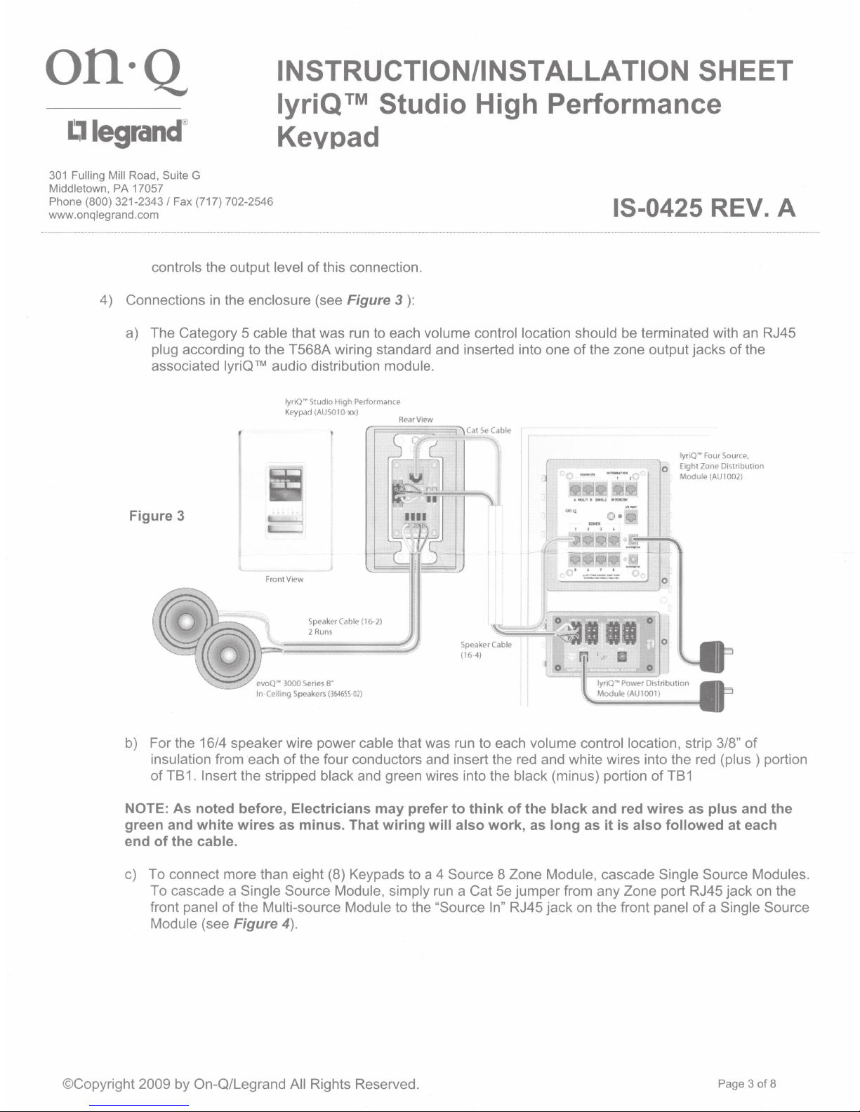
4) Connections
a) The Category 5 cable that was run to each volume control location should
plug according to the T568A wiring standard and inserted into one
associated lyriQ™ audio distribution module.
Figure 3
®
I Fax (717) 702-2546
in
the enclosure (see Figure 3
Keypad
lyriQ"" Studio Hi
Keypad (A
USO
gh
PPrf
ormance
1 0
XX)
):
Rear Vi
ew
15-0425 REV. A
be
terminated with
of
the zone output jacks
lyri
Q~
Four
Eight Zone
0
Modu
le
(AlJ
an
RJ45
of
the
Sourc;;o,
Di~tribution
1 002)
Fr
ontVrew
Spec'lker
Cab
le (16-
2)
01)
evoo••
In
Ce
iling Speakers
3000
2 R
Series
uns
8"
(364655
b) For the 16/4 speaker wire power cable that was run to each volume control location, strip 3/8" of
of
insulation from each
the four conductors and insert the red and white wires into the red
of TB1. Insert the stripped black and green wires into the black (minus) portion
NOTE: As noted before, Electricians may prefer to think
of
the black and red wires as plus and the
green and white wires as minus. That wiring will also work, as long as it
of
TB1
is
also followed at each
(plus)
portion
end of the cable.
c) To connect more than eight (8) Keypads to a 4 Source 8 Zone Module, cascade Single Source Modules.
run
a Cat
Se
To cascade a Single Source Module, simply
of
front panel
Module (see
the Multi-source Module to the "Source In" RJ45 jack on the front panel
Figure 4).
jumper from any Zone port RJ45 jack on the
of
a Single Source
©Copyright 2009 by On-Q/Legrand All Rights Reserved.
Page 3 of 8
 Loading...