

LEGRAND Keor MOD 25, Keor MOD 100, Keor MOD 150, Keor MOD 125, Keor MOD 175 Installation And Maintenance Manual
...
Keor MOD
Installation and maintenance manual
Part. LE11406AB-04/19-01 GF
Keor MOD
ENGLISH 3
EN
2

Keor MOD
Table of Contents
1 Introduction 5
1.1 Purpose of the manual 5
1.2 Symbols in the manual 5
1.3 Where and how to keep the manual 5
1.4 Update of the manual 6
1.5 Manufacturer’s liability and guarantee 6
1.5.1 Guarantee terms 6
1.5.2 Extension of the guarantee and maintenance contracts 7
1.6 Copyright 7
2. Regulatory and safety requirements 8
2.1 General notes 8
2.2 Denitions of “Skilled Technician” and “Operator” 8
2.2.1 Skilled Technician 8
2.2.2 Operator 8
2.3 Personal Protective Equipment 8
2.4 Hazard signs in the workplace 9
2.5 Signs on the equipment 9
2.6 General warnings 10
2.7 How to proceed in an emergency 11
2.7.1 First-aid procedures 11
2.7.2 Fire procedures 11
Installation and maintenance manual
3. Transportation and placement 12
3.1 Visual check 12
3.2 Equipment check 12
3.3 Transportation 13
3.4 Unpacking 14
3.5 Placement 15
4. Installation 17
4.1 Safety regulations 17
4.2 Electrical connections 17
4.2.1 Protective devices 18
4.2.2 Disassembly of the distribution panel 18
4.2.3 Earthing connection 23
4.2.4 Cable fastening 25
4.2.5 Backfeed protection 34
4.2.6 Input cables installation 35
4.2.7 Bypass cables installation 41
4.2.8 Output cables installation 45
4.2.9 Battery cables installation 49
4.3 Power modules installation 58
4.4 Battery drawers installation 60
4.5 SSS interface 66
4.5.1 Emergency Power O (EPO) 67
3

Table of Contents
5. Configuration and start-up 68
5.1 Pre-start-up checks 68
5.2 Start-up procedure 68
5.3 Switching o the UPS 70
6. Maintenance 71
6.1 Preventive maintenance 71
6.2 Periodical checks 71
6.3 Ordinary maintenance 72
6.3.1 Hot-swap procedure for the replacement of power modules 72
6.3.2 Installation/replacement of power modules with the UPS in maintenance bypass mode 76
6.3.2.1 Setting the UPS in maintenance bypass mode 76
6.3.2.2 Installation/replacement of power modules 76
6.3.2.3 Exit the UPS from the maintenance bypass mode 78
6.3.3 Removal of the SSS drawer 79
6.4 Battery drawers replacement 80
6.4.1 Installation/replacement of battery drawers with UPS in on-line mode 80
6.4.2 Installation/replacement of battery drawers with UPS in maintenance manual bypass 81
6.5 Replacing the fuses and surge arrester (DIN rail) 82
6.6 Extraordinary maintenance 83
7. Warehousing 84
7.1 UPS 84
7.2 Batteries 84
8. Dismantling 85
8.1 Battery disposal 85
8.2 UPS dismantling 85
8.3 Electronic component dismantling 85
9. Mechanical characteristics 86
9.1 Cabinets 86
9.2 Power module PM25 91
9.3 Battery drawer 92
9.4 Battery block 93
10. Technical data 94
11. Tables 98
4
1. Introduction
INDICATION
The instructions in this manual are intended for a SKILLED TECHNICIAN (paragraph 2.2.1)
Keor MOD
1.1 Purpose of the manual
The purpose of this manual is to provide the skilled technician (see paragraph 2.2.1) with instructions for safely installing
the Keor MOD UPS, also called “equipment” in the rest of the manual and carry out ordinary maintenance procedures.
Extraordinary maintenance operations are not dealt with because they are the sole preserve of the LEGRAND Technical
Support Service.
The reading of this manual is essential but does not substitute the skill of technical personnel who must have received
adequate preliminary training.
The intended use and configurations envisaged for the equipment as shown in this manual are the only ones allowed by
the Manufacturer.
Any other use or configuration must be previously agreed with the Manufacturer in writing and, in this case, the written
agreement will be attached to the installation and user manuals.
This manual also refers to laws, directives and standards that the skilled technician is required to be aware of and consult.
The original text of this publication, drafted in English, is the only reference for the resolution of disputes of interpretation
linked to translations into other languages.
1.2 Symbols in the manual
Some operations are shown in graphic symbols that draw the attention of the reader to the danger or the importance
they imply:
DANGER
This indication shows a danger entailing a high degree of risk that, if not avoided, will lead to death or serious injury or
considerable damage to the equipment and things around it.
Installation and maintenance manual
WARNING
This indication shows a danger entailing a medium degree of risk that, if not avoided, could lead to death or serious injury
or considerable damage to the equipment and the things around it.
CAUTION
This indication shows a danger entailing a low level of risk that, if not avoided, could lead to minor or moderate injury or
material damage to the equipment and the things around it.
INDICATION
This symbol indicates important information which should be read carefully.
1.3 Where and how to keep the manual
This manual must be kept in a safe, dry place and must always be available for consultation exclusively by the skilled
technician.
It is recommended to make a copy of it and file it away.
If information is exchanged with the Manufacturer or the authorized assistance personnel, it is essential to refer to the
equipment’s rating plate data and serial number.
INDICATION
The manuals provided with the equipment are an integral part of it and must therefore be kept for its entire lifetime. In
case of need (for example in case of damage that even partially compromises its consultation) the skilled technician is
required to get a new copy from the Manufacturer, quoting the publication code on the cover.
5

1. Introduction
1.4 Update of the manual
The manual reflects the state of the art when the equipment was put onto the market. The publication conforms to the
directives current on that date. The manual cannot be considered inadequate when new standards come into force or
modifications are made to the equipment.
Any addition to the manual the Manufacturer considers appropriate to send to the users, must be kept together with the
manual of which they will become an integral part.
The version of the manual updated to its latest release is available on the Internet at http://www.ups.legrand.com
1.5 Manufacturer’s liability and guarantee
The skilled technician and the operator shall scrupulously comply with the precautions and installation instructions indicated in the manuals. They must:
- always work within the operating limits of the equipment;
- always carry out constant and careful maintenance through a skilled technician who complies with all the procedures
indicated in the installation and maintenance manual.
The Manufacturer declines all indirect or direct responsibility arising from:
- assembly and cabling made by personnel not qualified and authorized by LEGRAND and not fully qualified according to
national standards to work on equipment presenting electrical hazards;
- assembly and cabling made without using safety equipment and tools required by national safety standards;
- failure to observe the installation and maintenance instructions and use of the equipment which differs from the specifications in the manuals;
- use by personnel who have not read and thoroughly understood the content of the user manual;
- use that does not comply with the specific standards used in the country where the equipment is installed;
- modifications made to the equipment, software, functioning logic unless they have been authorized by the Manufacturer in writing;
- repairs that have not been authorized by the LEGRAND Technical Support Service;
- damage caused intentionally, through negligence, by acts of God, natural phenomena, fire or liquid infiltration;
- damage caused by the use of batteries and protections not specified in the manuals;
- damage caused by improper unloading and transportation after delivery of the equipment;
- accidents caused by a wrong assembly of the safety protections or due to the lack of application of the safety labels
specified in the installation manual.
The transfer of the equipment to others also requires to hand over all the manuals. Failure to do it will automatically nullify
any right of the buyer, including the terms of the guarantee where applicable.
If the equipment is sold to a third party in a country where a different language is spoken, the original owner shall be responsible for providing a faithful translation of this manual in the language of the country where the equipment will be used.
1.5.1 Guarantee terms
The guarantee terms may vary depending on the country where the UPS is sold. Check the validity and duration with
LEGRAND’s local sale representative.
If there should be a fault in the product, contact the LEGRAND Technical Support Service which will provide all the instructions on what to do.
Do not send anything back without LEGRAND’s prior authorization.
The guarantee becomes void if the UPS has not been brought into service by a properly trained skilled technician qualified and authorized by LEGRAND (see paragraph 2.2.1).
If during the guarantee period the UPS does not conform to the characteristics and performance laid down in this manual, LEGRAND at its discretion will repair or replace the UPS and relative parts.
All the repaired or replaced parts will remain LEGRAND’s property.
LEGRAND is not responsible for costs such as:
- losses of profits or earnings;
- losses of equipment, data or software;
- claims by third parties;
- any damage to persons or things due to improper use, unauthorized technical alterations or modifications;
- any damage to persons or things due to installations where the full compliance with the standard regulating the specific
usage applications have not been guaranteed.
6

Keor MOD
1.5.2 Extension of the guarantee and maintenance contracts
The standard guarantee can be consolidated in a single extension contract (maintenance contract).
Once the guarantee period has passed, LEGRAND is available for giving a technical assistance service able to meet all
requirements, maintenance agreements, 24/7 availability and monitoring.
Please, contact the LEGRAND Technical Support Service for further information.
1.6 Copyright
The information contained in this manual cannot be disclosed to any third party. Any partial or total duplication of the
manual by photocopying or other systems, including electronic scanning, which is not authorized in writing by the Manufacturer, violates copyright conditions and may lead to prosecution.
LEGRAND reserves the copyright of this publication and prohibits its reproduction wholly or in part without previous
written authorization.
Installation and maintenance manual
7
2. Regulatory and safety requirements
DANGER
Before carrying out any operation on the equipment, it is necessary to read the entire manual carefully, especially
this chapter.
Look after this manual carefully and consult it repeatedly during installation and maintenance by a skilled technician.
2.1 General notes
The equipment has been made for the applications given in the manual. It may not be used for purposes other than those
for which it has been designed, or differently from those specified in this manual.
The various operations must be carried out according to the criteria and the chronology described in this manual.
2.2 Definitions of “Skilled Technician” and “Operator”
2.2.1 Skilled Technician
The figure that will carry out the installation, start up and ordinary maintenance is called “Skilled Technician”.
This definition refers to people qualified by LEGRAND who have the specific technical qualification and are aware of the
method of installing, assembling, repairing, bringing online and using the equipment safely.
In addition to the requirements listed in the section below for a general operator, the Skilled Technician is qualified
according to national safety standards to work under dangerous electrical voltage and uses the personal protective
equipment required by national safety standards for all the operations indicated in this manual (see the examples
listed in paragraph 2.3).
INDICATION
The safety manager is responsible for protection and company risks prevention according to what is indicated in European directives 2007/30/EC and 89/391/EEC regarding safety in the workplace.
The safety manager must ensure that all the people working on the equipment have received all the instructions concerning them in the manual, especially those contained in this chapter.
2.2.2 Operator
The figure assigned to the equipment for normal use is called “Operator”.
This definition refers to people who know how to operate the equipment defined in the user manual and have the following requisites:
1. technical education, which enables them to operate according to safety standards in relation to the dangers linked to
the presence of electric current;
2. training on the use of personal protective equipment and basic first aid interventions.
The company safety manager, in choosing the person (operator) who uses the equipment, must consider
- the person’s work fitness according to the laws in force;
- the physical aspect (not disabled in any way);
- the psychological aspect (mental stability, sense of responsibility);
- the educational background, training and experience;
- the knowledge of the standards, regulations and measures for accident prevention.
He shall also provide training in such a way as to provide thorough knowledge of the equipment and its component parts.
Some typical activities the operator is expected to carry out are:
- the use of the equipment in its normal functioning state and the restore of the functioning after it shuts down;
- the adoption of the necessary provisions for maintaining the quality performance of the UPS;
- the cleaning of the equipment;
- cooperation with personnel responsible for ordinary maintenance activities (Skilled Technicians).
2.3 Personal Protective Equipment
DANGER
The UPS poses a considerable risk of electric shocks and a high short circuit current. During installation, use and maintenance operations, the equipment mentioned in this section must be used.
People responsible for operating this equipment and/or passing close to it must not wear garments with flowing sleeves,
nor may laces, belts, bracelets or other metal pieces that might cause a danger.
8

Keor MOD
The following list sum up the minimum Personal Protective Equipment to wear always. Additional requirements may be
needed according to national safety standards.
Anti-accident and non-sparking shoes with rubber
sole and reinforced toe
Protective gloves for handling operations
Isolated rubber gloves for operations of connection
and work under hazardous voltage
Protective garments for electrical work
Protective face and head shield
Isolated tools
INDICATION
The skilled technician must work on electrical insulated carpet and he must not wear any kind of metal objects like watches, bracelets, etc.
2.4 Hazard signs in the workplace
The following signs must be exhibited at all points of access to the room where the equipment is installed:
Installation and maintenance manual
Electric current
This sign indicates the electrical live parts.
How to proceed in an emergency
Do not use water to quench fires but just the extinguishers specially designed for putting out fires in electrical
equipment.
No smoking
This sign indicates that smoking is not allowed.
2.5 Signs on the equipment
Displayed on the UPS are explanatory plates that can vary depending on the country the equipment is intended for and
constructional standards applied.
Make sure the instructions are adhered to. Removing these plates and working in a way that differs from what written
there, is strictly prohibited.
The plates must always be clearly read and they must be cleaned periodically.
If a plate deteriorates and/or it is no longer legible, even partially, the Manufacturer must be contacted for another one.
CAUTION
The plates must not be removed or covered. Signs in different languages are provided along with the equipment to
replace those in English. No other plates may be affixed to the equipment without the Manufacturer’s prior written authorisation
9

2. Regulatory and safety requirements
WARNING
Potential risks can be drastically reduced by wearing the Personal Protective Equipment listed in this chapter, which are
indispensable. Always operate with due care around dangerous areas marked by the appropriate warning notices on the
equipment.
2.6 General warnings
DANGER
The UPS works with dangerous voltages. Only skilled technicians qualified and authorized by LEGRAND must perform the
installation and ordinary maintenance operations. No part of the UPS can be repaired by the operator.
Extraordinary maintenance operations must be carried out by LEGRAND Technical Support Service personnel.
DANGER
Before beginning any installation and/or maintenance operation, make sure that all the DC and AC power sources are
disconnected.
The UPS and the external battery cabinet, if present, must be installed with an earth connection to avoid high leakage
currents. First connect the earthing cable.
Check during each installation and/or maintenance operation the continuity of the earthing system.
DANGER
The UPS is powered by its own DC energy source (batteries). The output terminals may have a dangerous voltage even if
the UPS is not connected to the AC power network.
Disconnect all battery drawers and external battery cabinets before performing any installation and/or maintenance
operation.
WARNING
A battery can present a risk of electrical shock and burns by high short-circuit circuit current. Failed batteries can reach
temperatures that exceed the burn thresholds for touchable surfaces. The following precautions should be observed
when working on batteries:
a) remove watches, rings or other metal objects.
b) use tools with insulated handles.
c) wear rubber gloves and boots.
d) do not lay tools or metal parts on top of batteries.
e) disconnect the charging source prior to connecting or disconnecting battery terminals.
f) determine if battery is inadvertently grounded. If inadvertently grounded, remove source from ground.
Contact with any part of a grounded battery can result in electrical shock. The likelihood of such shock can be reduced
if such grounds are removed during installation and maintenance (applicable to equipment and remote battery sup-
plies not having a grounded supply circuit).
g) never leave live cable terminals without an insulated protection.
h) When replacing batteries, replace with the same type and number of batteries or battery packs. There is the risk of
explosion if batteries are replaced by an incorrect type.
Do not dispose of batteries in a fire. The batteries may explode.
Do not open or mutilate batteries. Released electrolyte is harmful to the skin and eyes. It may be toxic. The batteries
installed inside the cabinet must be disposed of correctly. For the disposal requirements refer to local laws and relevant
standards.
INDICATION
The UPS functions with TT, IT, TN-C and TN-S systems. Input and output neutral are referenced to the same neutral potential: the output neutral status is the same as the input neutral status.
When the output load needs a different neutral status, it is necessary to place downstream of the UPS a suitably scaled
isolation transformer that must be protected in compliance with the standards in force.
10
CAUTION
Do not open the battery fuse holders while the UPS is powering the loads in battery mode.
Keor MOD
WARNING
To reduce the risk of fire or electric shock, the UPS must work in closed, clean environments with controlled temperature
and humidity. It must be kept away from inflammable liquids and corrosive substances. The room temperature must not
be above +40°C (+104°F) and the relative humidity must be a maximum of 95% not condensing.
WARNING
Keor MOD is a category C3 UPS according to the standard EN62040-2.
The UPS is a product for commercial and industrial application in the second environment – installation restrictions or
additional measures may be needed to prevent disturbances.
INDICATION
When the UPS is used for special applications such as life support systems or any other application where a product failure
is likely to cause substantial harm to people, it is mandatory to contact LEGRAND to confirm the possibility of the equipment to meet the requested level of safety, performance, reliability and compliance with applicable laws, regulations and
specifications.
Installation and maintenance manual
CAUTION
- While maintenance operations are being carried out, “Maintenance work in progress” signs must be affixed in the de-
partment in such a way that they can be easily seen from any access area.
- The connection of the equipment (and of any accessory devices) signs must always be perfectly grounded to discharge
short-circuit currents and electrostatic voltages. The input voltage must correspond with the value shown on the rating
plate. Current adapters must not be used under any circumstances. Pay attention to polarity when connecting.
- Any intervention on the equipment must be done only after it has been disconnected from the power supply network
by means of a switch disconnector and must be locked with an appropriate padlock.
- The UPS must not be turned on if liquid is leaking from the batteries.
- Depositing flammable material near the equipment is strictly forbidden. The equipment should always be locked, and
only specifically trained personnel are allowed access to it.
- Do not disable any safety, notification or warning device and do not ignore any alarm, warning message or notice, no
matter whether they are generated automatically or represented by plates fixed to the equipment.
- Do not run the equipment with fixed protections not installed (panels etc.).
- In case of breaking, buckling or malfunctioning of the equipment or parts of it, repair or replace immediately.
- When replacing fuses, only use ones of the same type.
- The replacement of the batteries is an operation intended to be carried out by a skilled technician.
- Keep a register in which to enter the date, time, type, performer’s name and any other useful information about each
and any routine and extraordinary maintenance operation.
- Do not use oils or chemical products for cleaning because they could scratch, corrode or damage certain parts of the
equipment.
- The equipment and workplace must be kept completely clean.
- Upon completion of the maintenance operations, before connecting the power supply, carefully check that no tools
and/or material of any kind have been left next to the equipment.
INDICATION
The skilled technician must not leave at the disposal of the operator:
- the keys for opening the UPS door;
- the installation and maintenance manual.
2.7 How to proceed in an emergency
The following information are general. For the specific interventions consult the regulations in force in the country where
the equipment is installed.
2.7.1 First-aid procedures
When administering first aid, adhere to the company rules and the usual procedures.
2.7.2 Fire procedures
Do not use water to quench fires but just the extinguishers specially designed for putting out fires on electrical equipment.
11

3. Transportation and placement
3.1 Visual check
On delivery of the UPS, carefully inspect the packaging and the equipment for any damage that might have occurred
during transport. Check there is no damage to the indicator on the outer label reading “Shock Watch”.
If there is possible or ascertained damage, immediately inform:
- the transporter;
- the LEGRAND Technical Support Service.
Check that the equipment corresponds with the items indicated in the delivery documentation.
If the UPS must be stored, follow the instructions of Chapter 7.
3.2 Equipment check
The equipment and the relative supplied accessories must be in perfect conditions.
Check that:
- the shipping data (address of the recipient, no. of packages, order no, etc.) correspond to what is contained in the deliv-
ery documentation;
- the technical rating plate data on the label applied to the UPS correspond with the material described in the delivery
documentation;
- the documentation accompanying the equipment includes the installation and user manuals.
In case of discrepancy, immediately inform the LEGRAND Technical Support Service before commissioning the equipment.
The content of the supply is subject to thorough checking before the shipment. Nonetheless it is always advisable to
check that it is complete and in order on receiving the material.
The following list is general:
- 1 UPS (empty cabinet) with keys to close the doors;
- 1 accessory box;
- user manual;
- installation and maintenance manual.
In case of defects and/or missing items, immediately inform the LEGRAND Technical Support Service before commissioning the equipment.
INDICATION
The installation manual must be used and consulted only by Skilled Technicians.
INDICATION
Power modules and battery drawers to be installed must be bought separately.
12

Keor MOD
3.3 Transportation
WARNING
The UPS must be placed and stand in a vertical position throughout the transportation. It shall also be packed properly.
Move the UPS very carefully, lifting it as little as possible and avoiding dangerous swings or falls.
Follow always the directions indicated in the symbols present on the packaging.
The equipment must always be handled by trained and instructed personnel. Comply with the safety regulations in force
in your country relative to the usage of lifting equipment and/or accessories.
For any lifting, use a forklift or a transpallet with an adequate carrying capacity, placing the forks in the specific spaces of
the base and making sure they come out on the other side by at least twenty centimetres.
Installation and maintenance manual
Keor MOD UPS has four wheels at the bottom of the cabinet. Before installations and while it is still empty, it can be moved
by hand by at least two people.
CAUTION
Do not move the UPS after the installation or following the insertion of the power modules.
13
3. Unpacking and moving
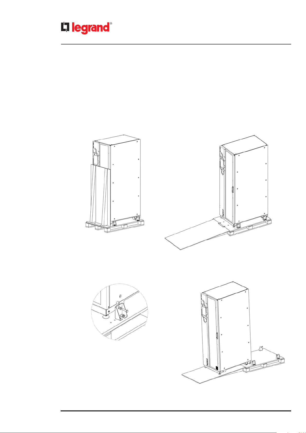
3.4 Unpacking
To remove the packaging material, two people are required and they must comply comply with the following procedure:
- bring the UPS to the installation site using a forklift and/or a transpallet with suitable characteristics (see fig. 1);
- remove the plastic film and cardboards protecting the UPS;
- bring down the wooden chute attached to the pallet (see fig. 2)
- loose the screws of the brackets that fix the equipment on the pallet (see fig. 3);
- gently slide by hand the equipment along the chute using the wheels (see fig. 4).
1
3
2
4
14
Keor MOD
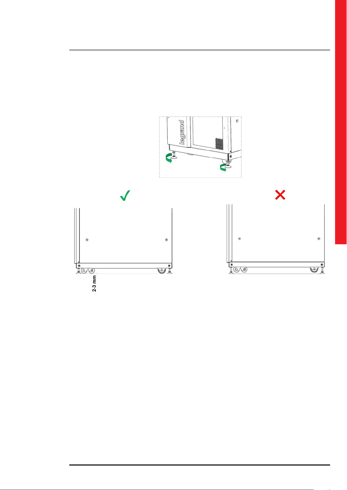
3.5 Placement
When the UPS is in the final position for the installation, unscrew counterclockwise the feet on the front and rear of the
cabinet to position it.
Make sure that all the wheels and feet adhere to the floor.
Installation and maintenance manual
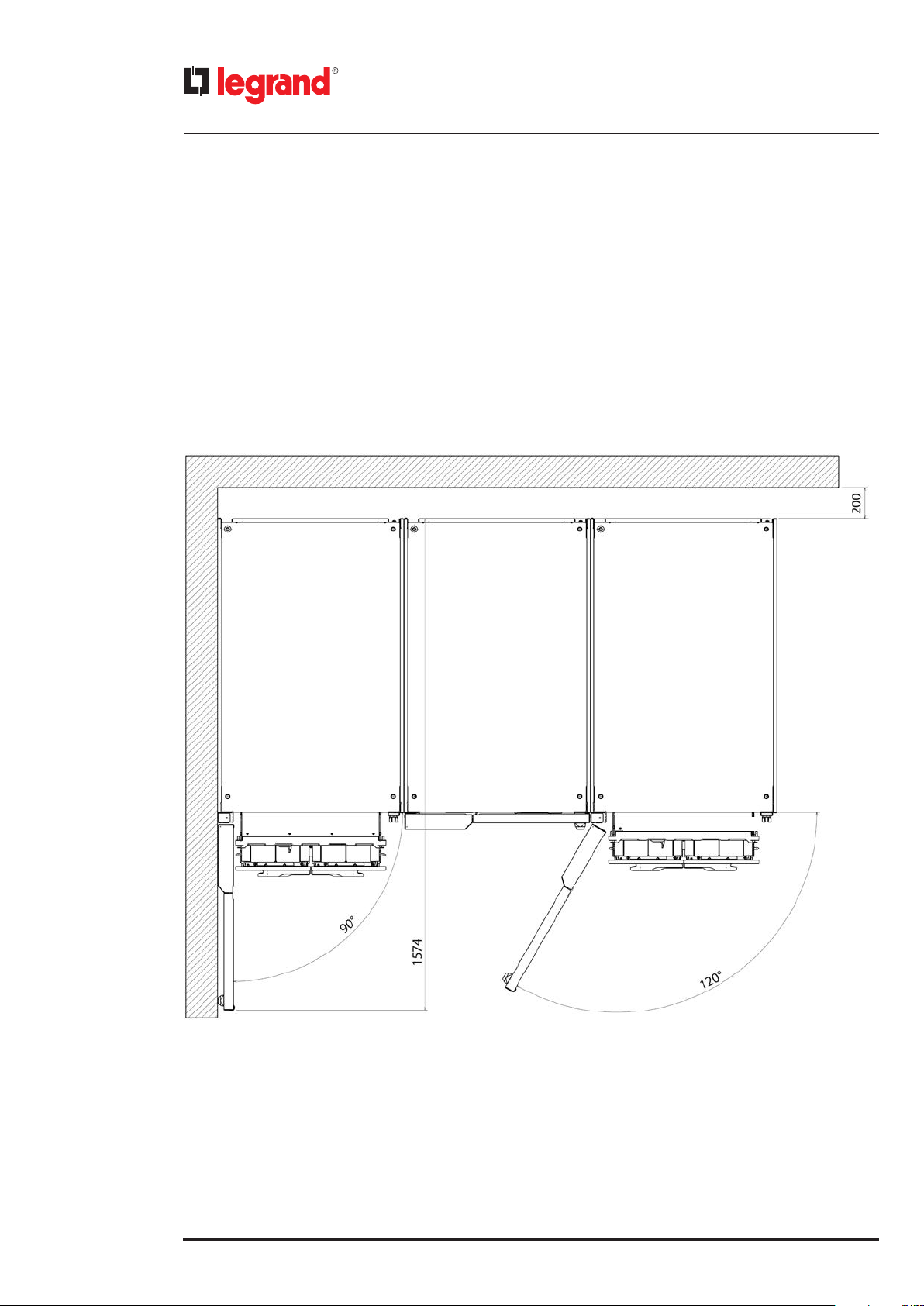
(all the dimensions are in mm)
15
3. Unpacking and moving
The UPS must be positioned respecting the following conditions:
- do not cover the cooling vents of the power modules and keep a clearance of 20 cm beyond the cabinets real panels;
- keep a clearance of 160 cm on the front to allow the opening of the door;
- temperature and humidity must be within permitted limits;
- fire regulations must be respected;
- the wiring must be simply made;
- front and rear accessibility must be available for assistance or periodic servicing;
- the cooling flow of air must be guaranteed;
- the air conditioning system must be adequately sized;
- dust, corrosive and explosive atmospheres must be absent;
- the installation site must be free of vibration;
- the support surface must be sized for the weight necessary to support the equipment:
- regulate the equipment feet to have perfect perpendicularity and level of the UPS compare with the floor.
16
POWER MODULE EXTRACTION
BATTERY DRAWERS EXTRACTION
POWER MODULE EXTRACTION
BATTERY DRAWERS EXTRACTION
To safeguard the batteries as well as possible it is necessary to bear in mind that their average lifetime is strongly influenced by the operating room temperature. Position the UPS in an environment with a temperature range between +20°C
(+68°F) and +25°C (+77°F) to guarantee the optimum life of the batteries.
Before proceeding with the installation operations, make sure that there is enough lighting to clearly see every detail.
Provide artificial lighting if the natural lighting does not satisfy this requirement.
In case of maintenance operations in places that are not sufficiently well lit, portable lighting systems must be used,
avoiding shadows that prevent or reduce visibility on the point where you intend to work or on the surrounding areas.
Keor MOD
4. Installation
DANGER
All UPS installation operations must be carried out exclusively by a SKILLED TECHNICIAN qualified and authorized
by LEGRAND (paragraph 2.2.1).
4.1 Safety regulations
DANGER
Before carrying out any installation operation you must read and apply the following:
- The UPS has a high leakage current. The earthing connection must be connected before cabling the UPS input. The
switchgear must have a safe connection with the earthing and an adequate protection as required by the installation
standards.
- The UPS must only be installed in a fixed way with a thermal-magnetic circuit breaker placed upstream of it. Connection
to the mains via traditional type plug is not allowed.
- A circuit to protect from voltage backfeed made as in the diagrams shown in paragraph 4.2.5 must be provided outside
the UPS.
- The switchgear or the disconnector switch must be installed near the equipment and must be easily accessible.
- A warning label must be placed on all the mains disconnector switches installed away from the area of the UPS to remind the
assistance personnel of the fact that the circuit is connected to a UPS. The label must contain the following or equivalent text:
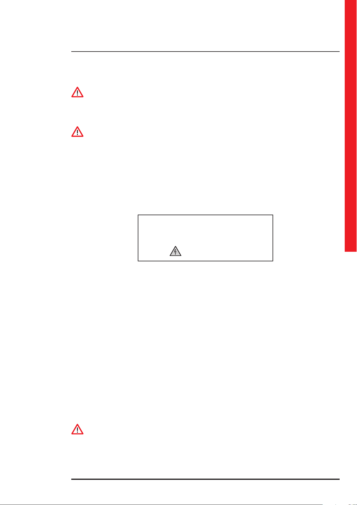
Installation and maintenance manual
Before working on this circuit
- Isolate Uninterruptible Power System (UPS)
- Then check for the presence of Hazardous Voltage
between all terminals including the protective earth
Risk of Voltage Backfeed
- Do not carry out the installation in presence of water or humidity.
- Open only the UPS panels necessary for the electrical connections. After that, close and fix them.
- Check there is no mains voltage on the equipment.
- Check that the loads are off and disconnected from the UPS.
- Check that the UPS is off and no voltage is present.
- Check that the fuse breakers on the external battery cabinets (if present) are open.
- Check that all battery drawers (if present) are not fully inserted in the UPS cabinet.
- Check that the mains input voltage and frequency correspond with the values indicated in the technical data on the
UPS rating plate.
- Check that the earthing has been carried out in compliance with IEC (International Electrotechnical Commission) stand-
ards or local regulations.
- Check that the electrical system has been fitted with the necessary differential and thermal-magnetic protections up-
stream of the UPS.
- The energy quality of the electrical network should comply with the individual voltage harmonics compatibility levels
defined by EN 61000-2-2. For more severe conditions, a power quality audit is required during the UPS commissioning
by the LEGRAND Technical Support Service in orded to check the compatibility.
4.2 Electrical connections
The electrical hook-up of the UPS to the switchgear or to the external battery cabinets is part of the installation that is not
normally performed by the UPS manufacturer. For this reason, the indications that follow are to be considered approximate and it is recommended that the electrical connections are based on local installation standards.
After removing the UPS from the packaging and positioning it in its definitive place, the Skilled Technician can begin to
make the electrical connections.
WARNING
The choice of cables type and their cross sections depending on the rated current and their installations must be made as
indicated by the local installation standards and it is a responsibility of the Skilled Technician.
The input current and the output power of the UPS are indicated in chapter 10 and the battery current in table 4 of chapter 11.
INDICATION
Chapter 11 includes tables with the recommended cables, fuses, automatic and differential breakers.
17
4. Installation
4.2.1 Protective devices
To ensure proper protection from overloads, output short-circuits or electrical shocks, it is necessary to install adequate
automatic residual-current and thermal-magnetic breakers upstream of the UPS on the input line. In case there is a separate bypass line, the residual current earth leakage protection system must be common for the AC input and bypass lines
and must be installed upstream.
The protective devices must be selected according to the indications in the tables shown in chapter 11.
CAUTION
The equipment can cause a d.c. current in the PE conductor. Where a residual current-operated protective device (RCD) is
used for protection against electrical shock, only an RCD of Type B is allowed on the supply side of this product.
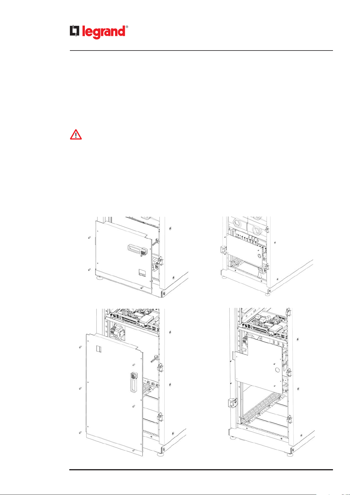
4.2.2 Disassembly of the distribution panel
To carry out all the electrical connection operations, it is necessary to unscrew the screws that fix the distribution panel
to the cabinet. The screws must be saved to close the distribution panel at the end of the installation (hex socket M6x20
screws along with M6 toothed washers).
Unscrew also the screws that fix the plexiglass protection panel and save them to close the panel and the end of the
installation (Phillips pan head M4x10 screws).
The following pictures show how to disassemble the panels:
KEOR MOD 125
KEOR MOD 250
18

Keor MOD
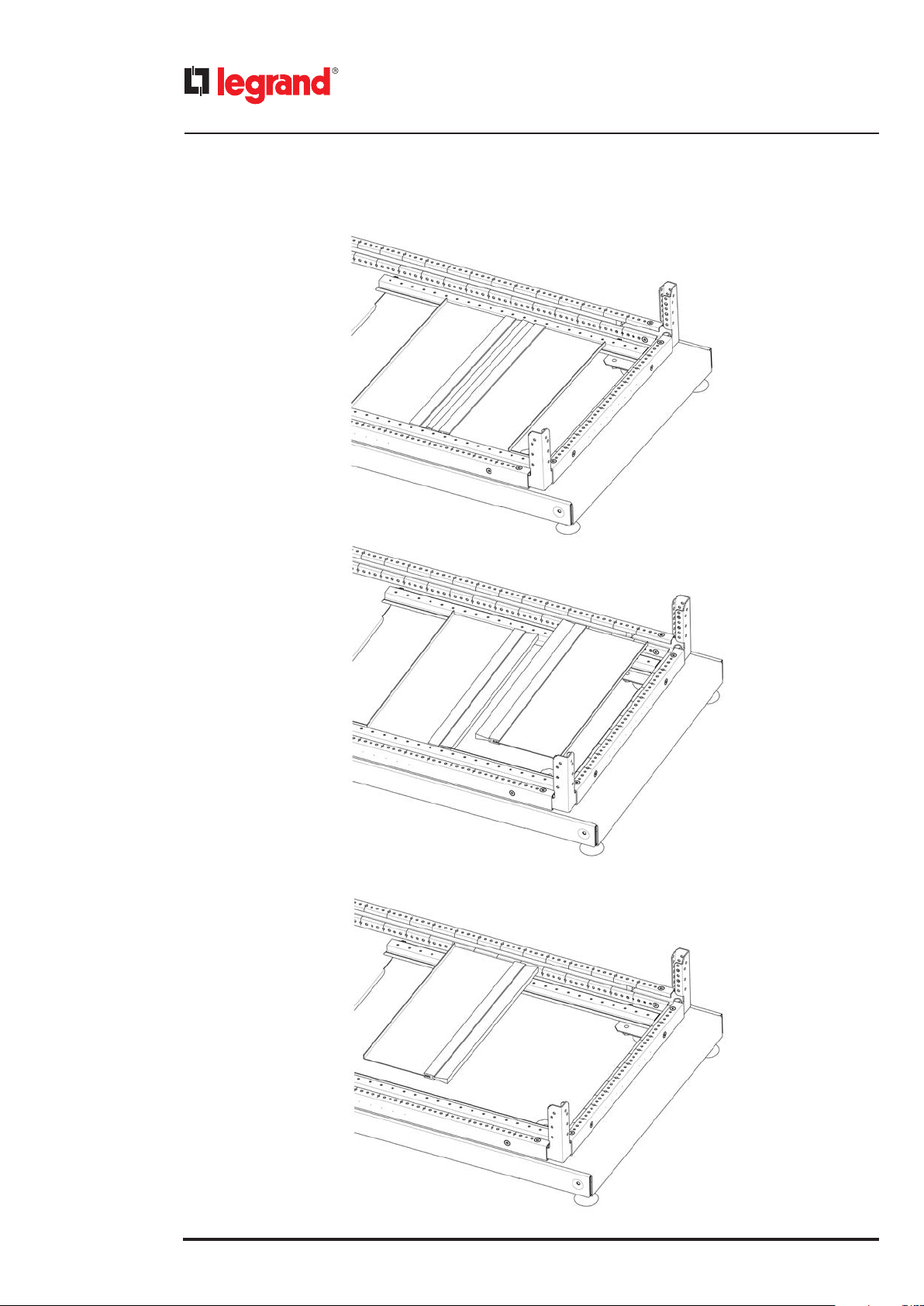
To insert the cables in the cabinet, it is necessary to remove the panels at the bottom of the cabinet according to the
following sequence:
1
2
Installation and maintenance manual
19
4. Installation
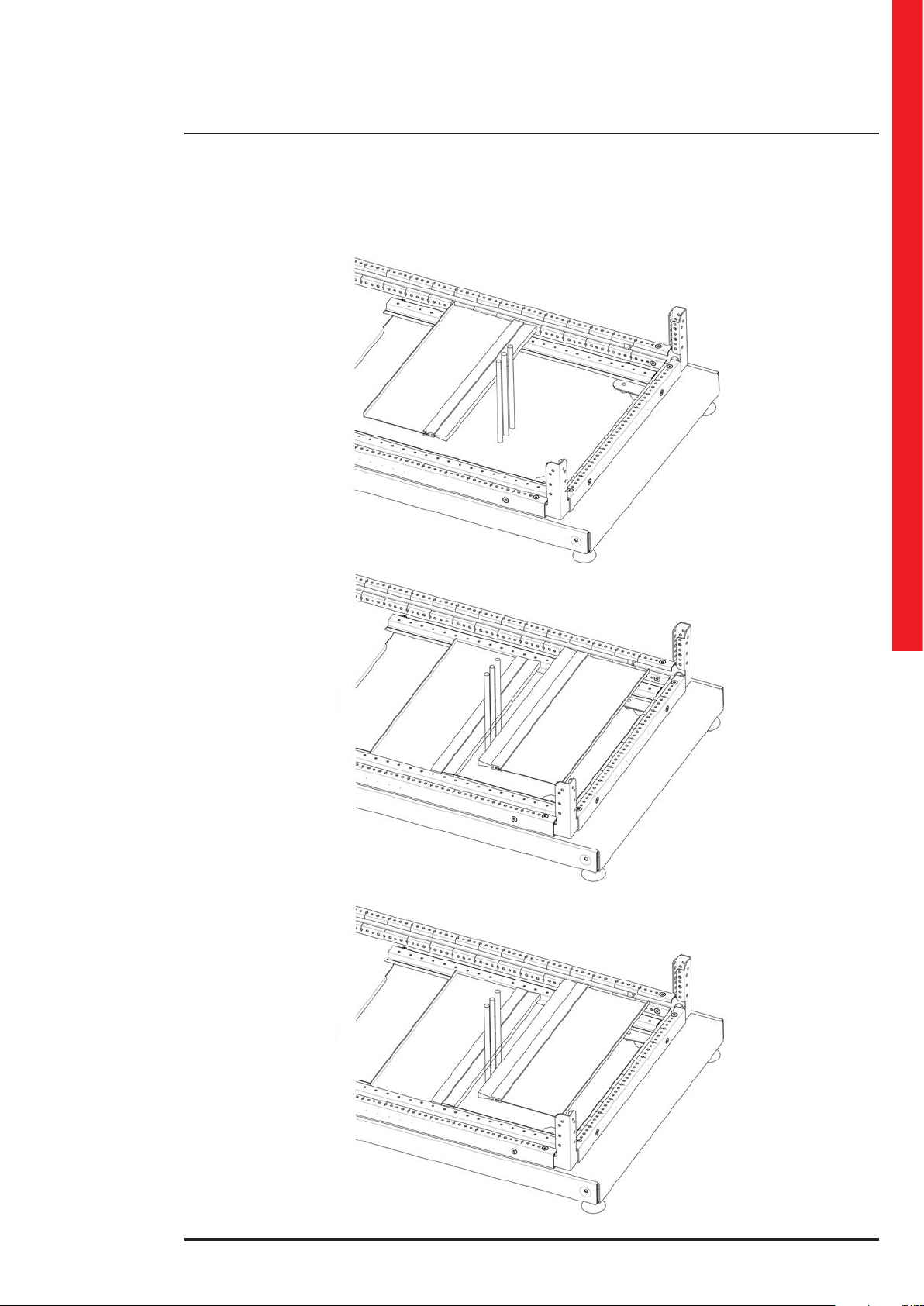
3
4
20
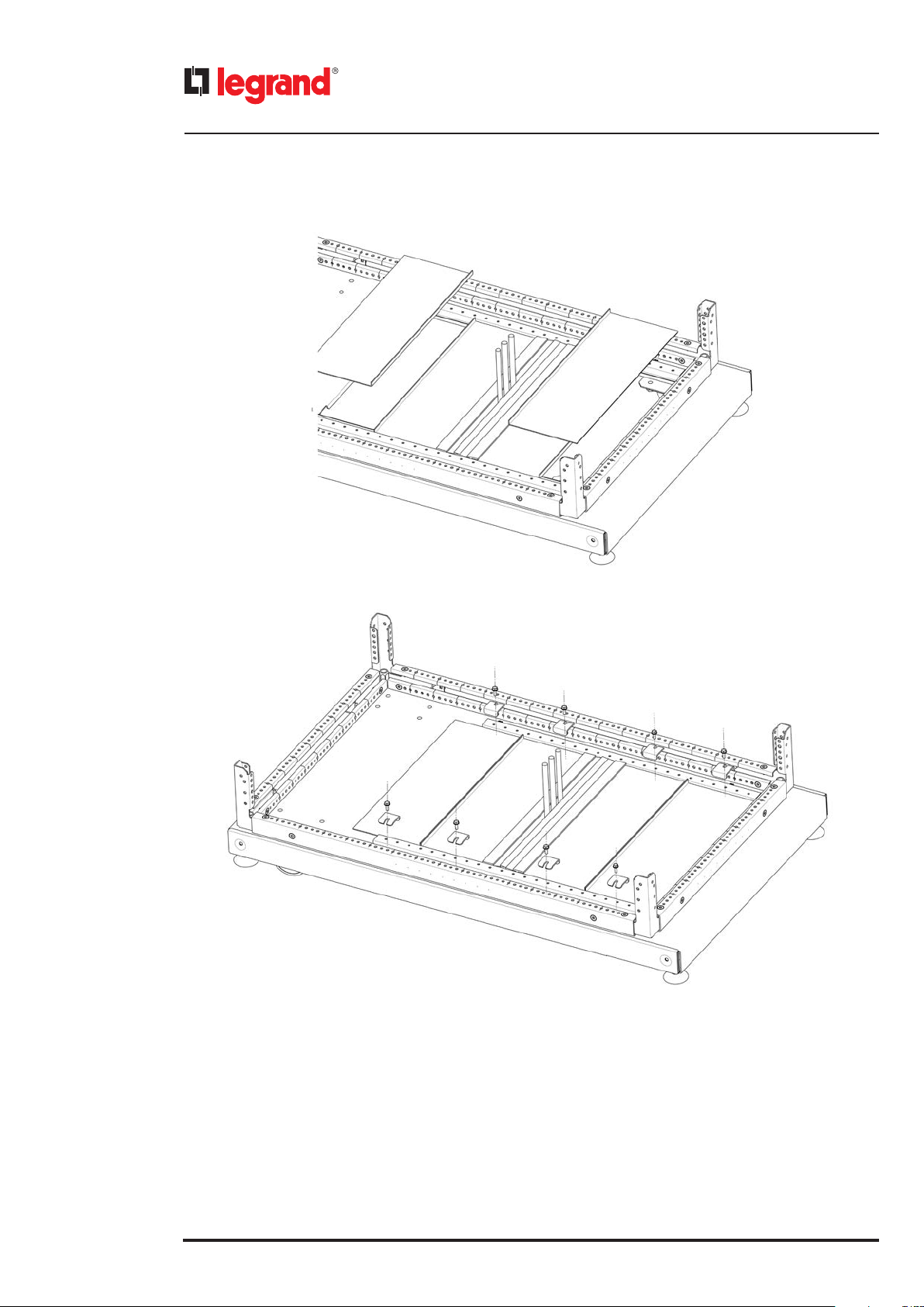
5
Insert the cable and add the panels according to the following sequence:
6
Keor MOD
Installation and maintenance manual
7
8
21
4. Installation
9
10
22
Keor MOD
4.2.3 Earthing connection
Before carrying out any other installation operation, connect the earthing wiring coming from the low voltage switchgear
to one of the earthing bars located on the left and right side of the busbars connection system.
The minimum cross-sectional area of the earthing conductor must be chosen according to the following criteria:
• if the cross-sectional area S of the phase conductors is S ≤ 16 mm2, the minimum cross-sectional area of the earthing
conductor must be the same as the phase conductors;
• if the cross-sectional area S of the phase conductors is 16 mm2 < S ≤ 35 mm2, the minimum cross-sectional area of the
earthing conductor must be16 mm
• if the cross-sectional area S of the phase conductors is S > 35 mm2, the minimum cross-sectional area of the earthing
conductor must be S/2 mm
Each earthing cable must be crimped with M8 eyelets and fixed to the earthing metal bar using hex M8x20 screws along
with M8 flat washers and M8 grower washer.
The grower washer must be put on the top of the flat washer.
2
;
2
.
Installation and maintenance manual
KEOR MOD 125 – earthing bars
23
4. Installation
24
KEOR MOD 250 – earthing bars
Keor MOD
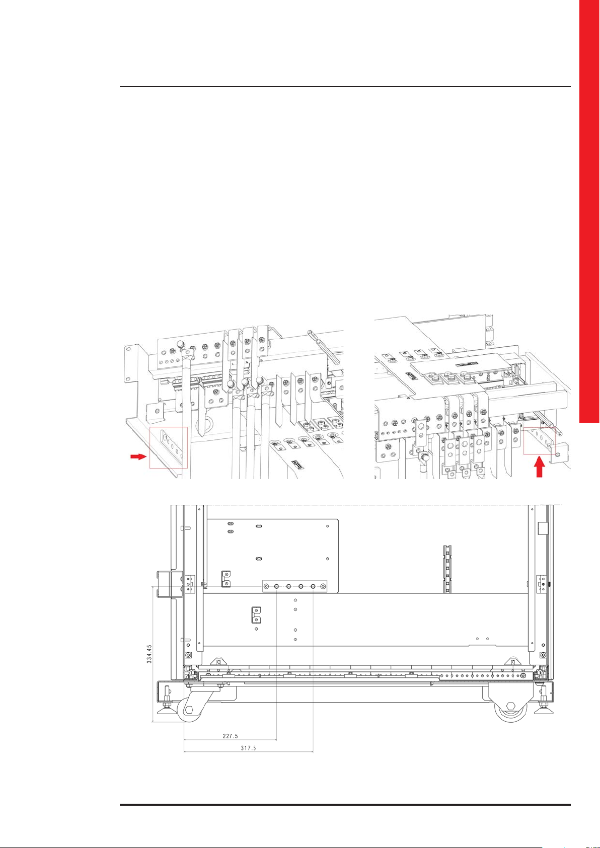
4.2.4 Cable fastening
In the accessory box there are two metal bars for Keor MOD 125 and three metal bars for Keor MOD 250. They are used
along with the plastic supports for cable ties to fasten the installation cables.
Each bar must be fixed to the cabinet using two hex M8x14 screws.
The plastic supports for the cable ties must be fixed on the bar using the M6 torx pan head screws.
Installation and maintenance manual
(all the dimensions are in mm)
KEOR MOD 125 – view of the two metal bars for cable fastening
25
4. Installation
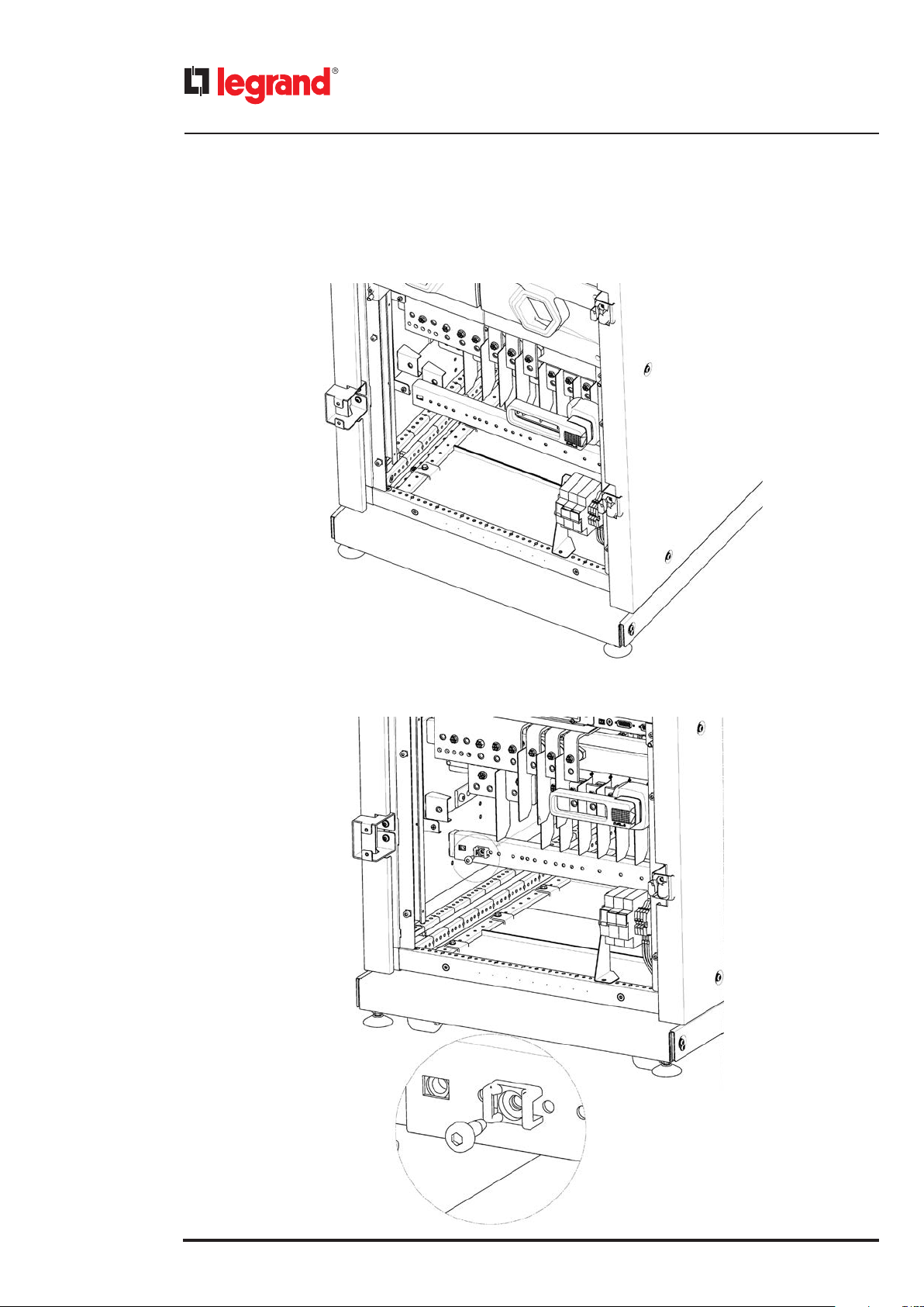
The fastening of the battery, input and output cables on Keor MOD 125 must be done according to the following steps:
1) Fix the first metal bar to the cabinet, behind the surge arrester and the fuse holders, using two hex M8x14 screws.
2) Fix the plastic supports for cable ties using M6 torx pan head screws.
26
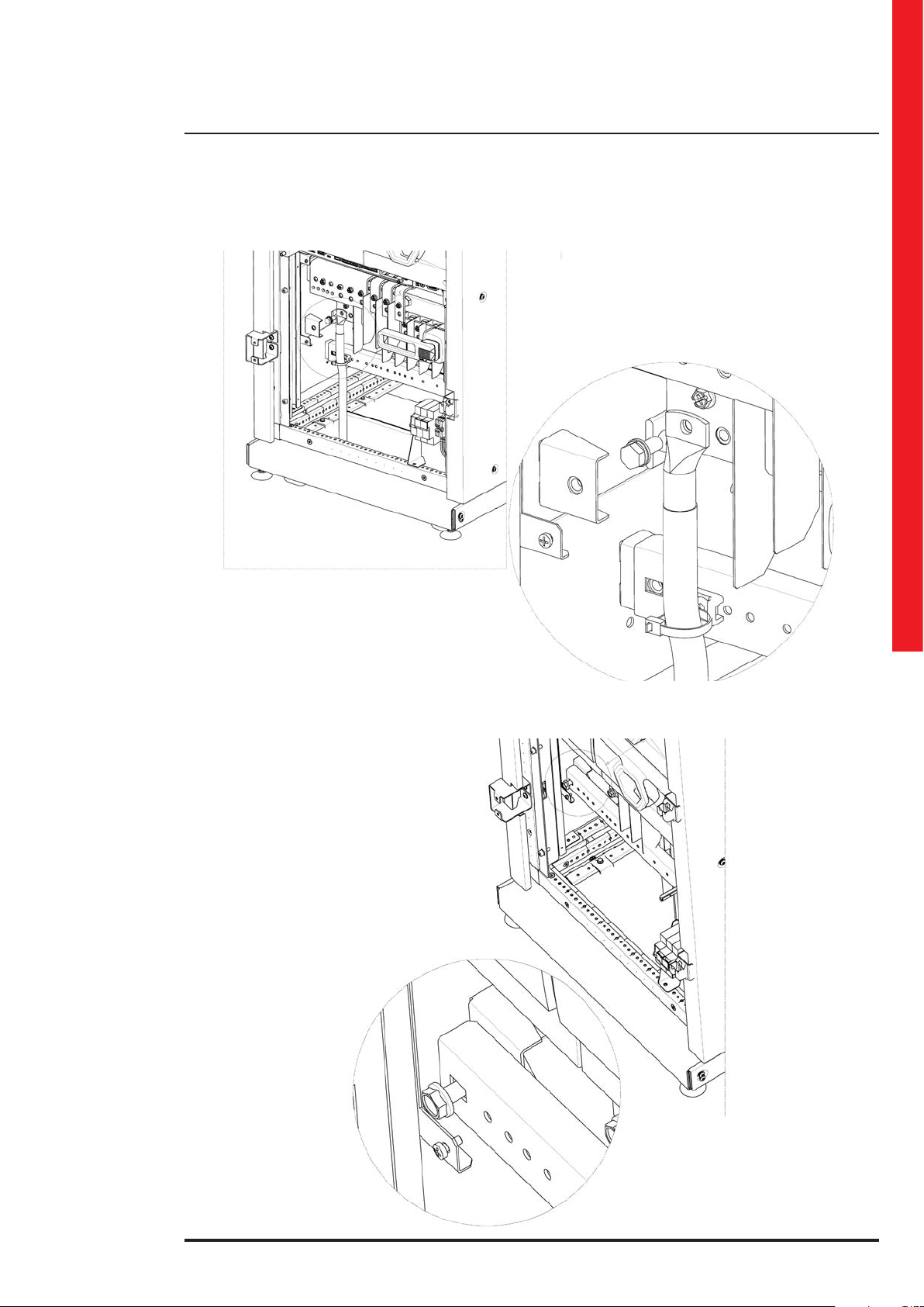
3) Fix the cables with cable ties.
Keor MOD
Installation and maintenance manual
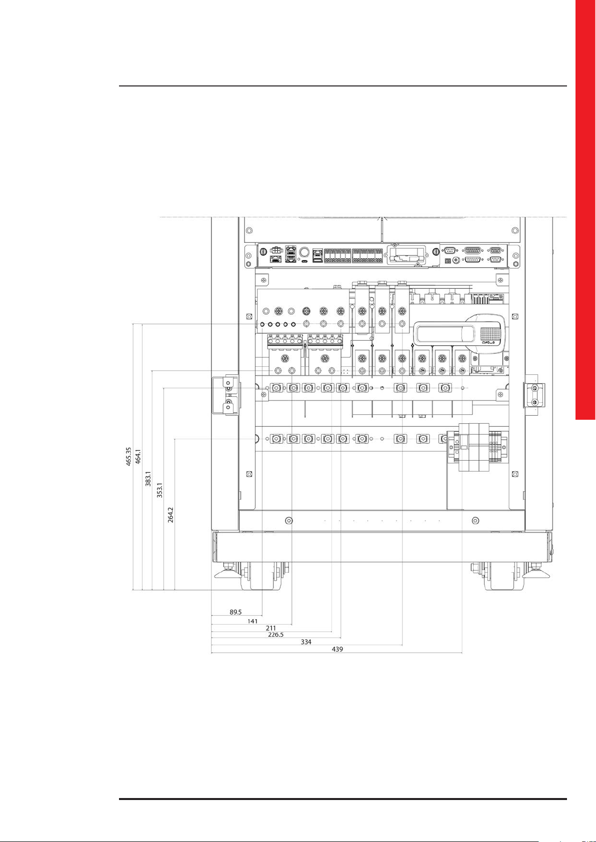
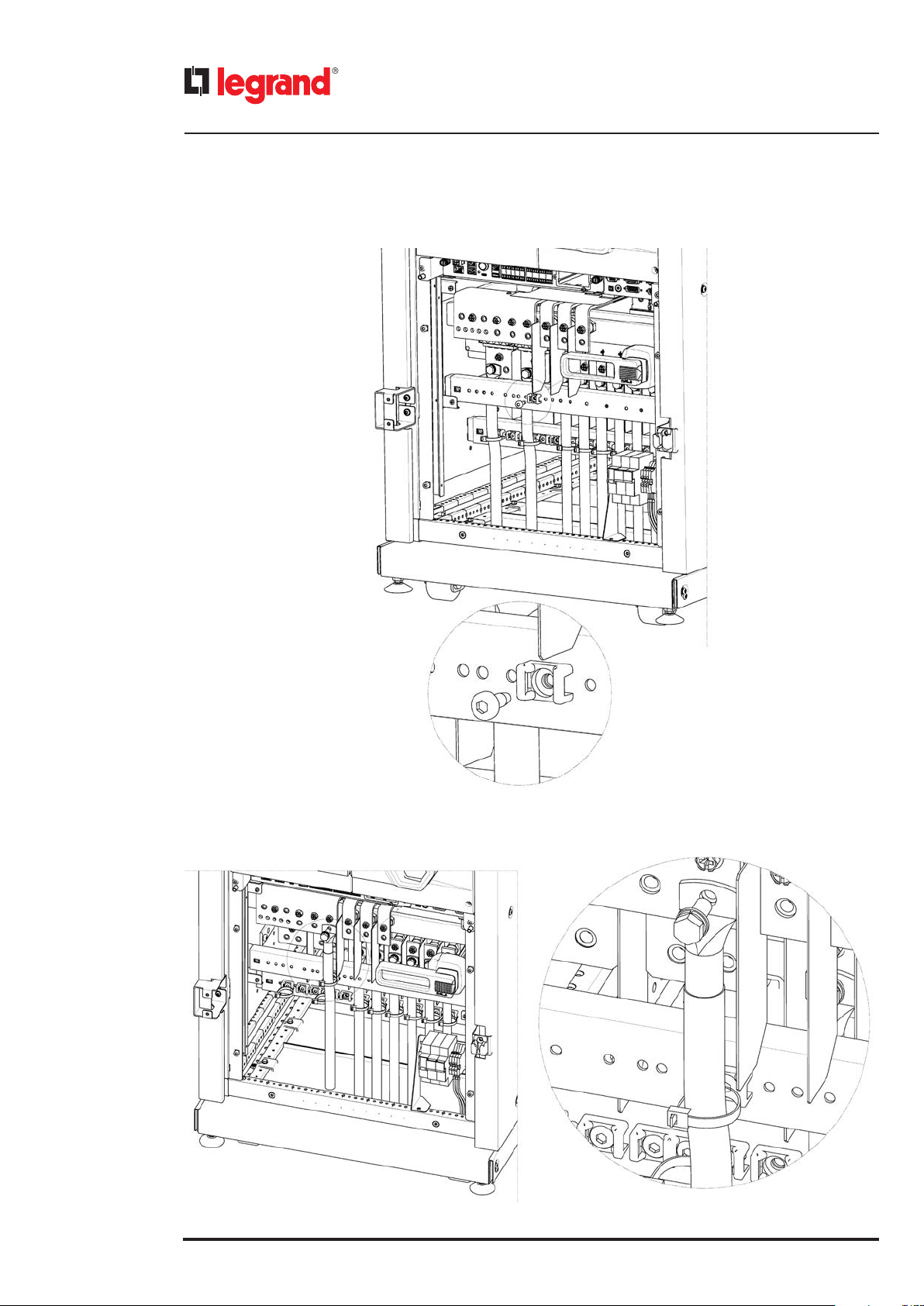
The fastening of the neutral and output cables on Keor MOD 125 must be done according to the following steps:
1) Fix the second metal bar to the cabinet, close to the maintenance manual bypass switch, using two hex M8x14 screws.
27
4. Installation
2) Fix the plastic support for cable ties using M6 torx pan head screws.
28
3) Fix the cables with cable ties.
Keor MOD
Installation and maintenance manual
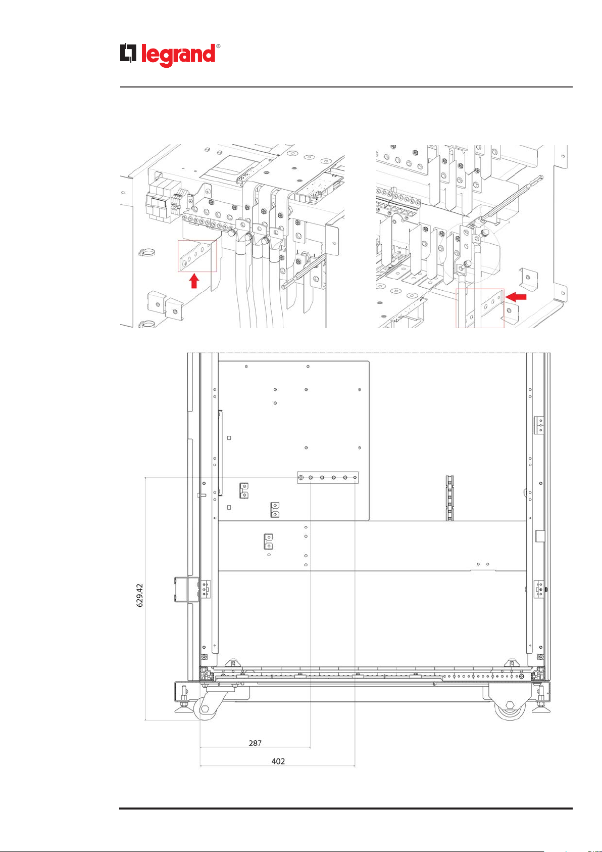
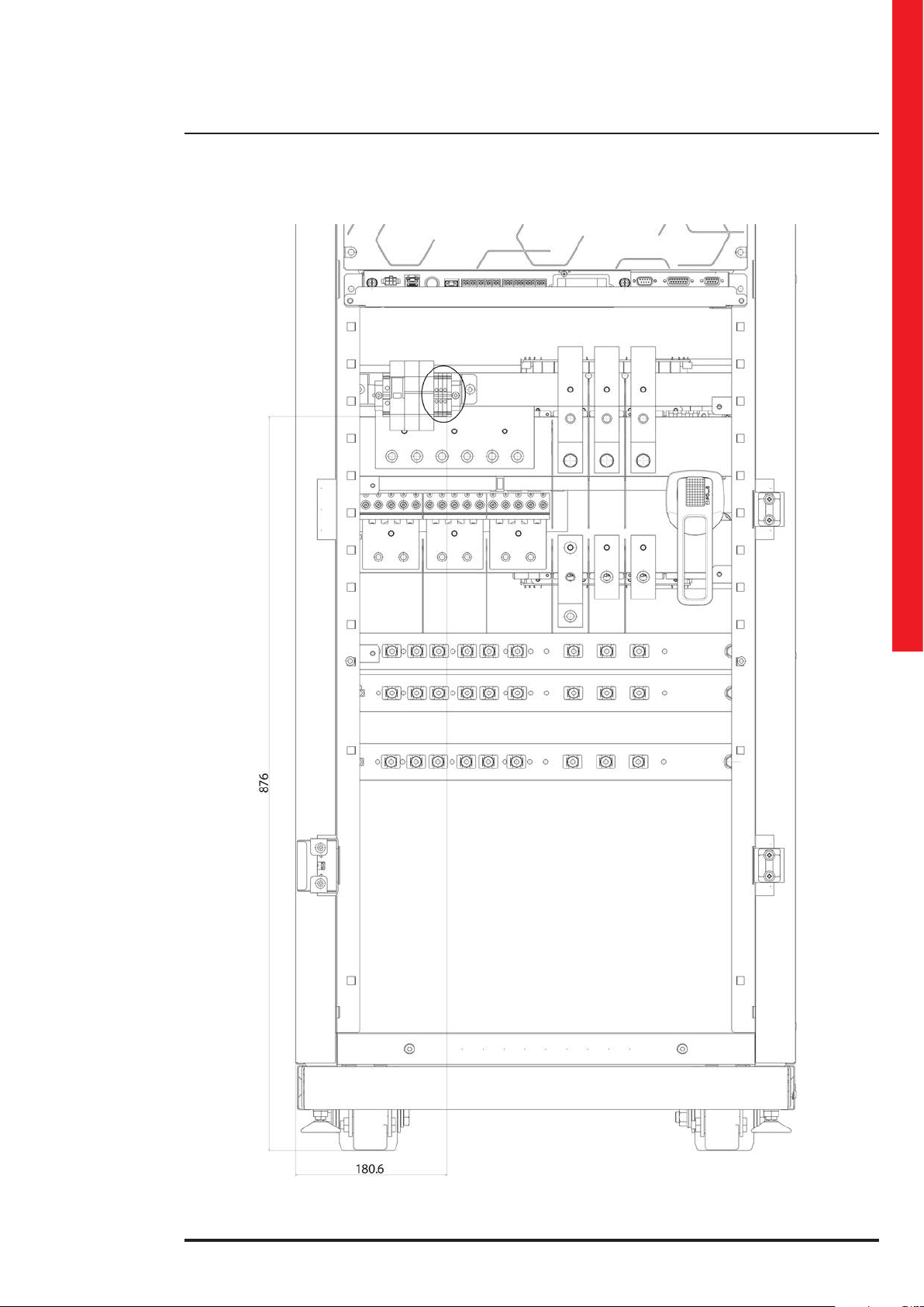
(all the dimensions are in mm)
KEOR MOD 250 – view of the three metal bars for cable fastening
29
4. Installation
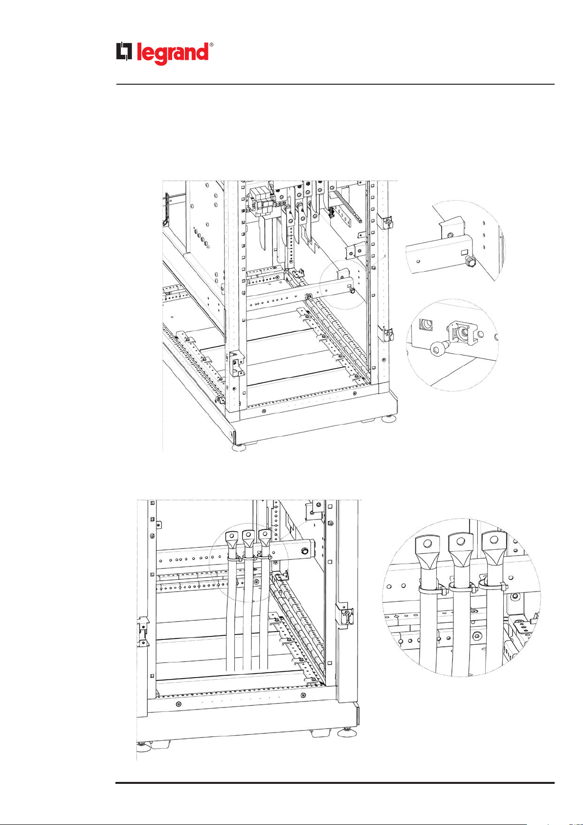
The fastening of the battery and output cables on Keor MOD 250 must be done according to the following steps:
1) Fix the first metal bar at the bottom of the cabinet using two hex M8x14 screws. Then fix the plastic support for the
cable ties using M6 torx pan head screws.
2) Fix the cable with cable ties.
30
 Loading...