

LEGRAND KEOR HPE UPS 200 KVA, UPS KEOR HPE 200 kVA Installation And Start-up Manual

Installation and start-up of KEOR HPE UPS 200 kVA
Installazione e avviamento KEOR HPE UPS 200 kVA
Rev.
Descrizione
Description
Data
Date
Emesso
Issued
Approvato
Approved
Lingua
Language
Pagina
Page
di Pag.
of Pag.
A Emissione / First issue 27.02.2017 R. Soldani G. Senesi
E/I 1 87
Codice / Code
OMP061
44
INSTALLATION AND START-UP OF
KEOR HPE UPS 200 KVA
INSTALLAZIONE E AVVIAMENTO UPS
KEOR HPE 200 KVA
Index / Indice
ENGLISH LANGUAGE .............................................................................. 8
1 SCOPE ............................................................................................. 10
2 SAFETY RULES AND WARNINGS ................................................. 11
2.1 USE OF THE UPS .................................................................................................... 11
2.2 UPS RATING PLATE ............................................................................................... 12
2.3 SPECIAL SAFETY WARNINGS ............................................................................... 13
2.3.1 General warnings ............................................................................................ 13
2.3.2 Personnel ......................................................................................................... 13
2.3.3 Transport and handling .................................................................................. 13
2.3.4 Installation ....................................................................................................... 14
2.3.5 Electrical connection ...................................................................................... 15
2.3.6 Operation ......................................................................................................... 16
2.3.7 Maintenance .................................................................................................... 17
2.3.8 Storage ............................................................................................................. 18
2.4 ENVIRONMENTAL PROTECTION ........................................................................... 18
2.4.1 ISO 14001 certification .................................................................................... 18
2.4.2 Recycling of packing materials ...................................................................... 18
2.4.3 Device disposal ............................................................................................... 18
3 INSTALLATION................................................................................ 19
3.1 RECEIPT OF THE UPS ............................................................................................ 19

Installation and start-up of KEOR HPE UPS 200 kVA
Installazione e avviamento KEOR HPE UPS 200 kVA
2 OMP06144 REV. A
3.1.1 Storage ............................................................................................................ 19
3.2 HANDLING OF THE UPS ........................................................................................ 20
3.3 POSITIONING AND INSTALLATION ...................................................................... 21
3.3.1 Base plan, static load and weights ................................................................ 22
3.3.2 Overall dimensions, clearances and ventilation ........................................... 23
3.3.3 Environmental installation conditions .......................................................... 25
3.4 POSITIONING AND CONNECTION OF THE BATTERIES ...................................... 27
4 ELECTRICAL CONNECTION ........................................................... 28
4.1 CONNECTION OF THE POWER CABLES .............................................................. 29
4.2 BACKFEED PROTECTION DEVICE ....................................................................... 31
4.3 TERMINAL BOARDS............................................................................................... 32
4.4 BATTERY ................................................................................................................ 33
4.5 CONNECTION OF THE AUXILIARY CABLES ........................................................ 34
4.5.1 External manual bypass ................................................................................. 34
4.5.2 NORMAL/BYPASS selector ............................................................................ 34
4.5.3 UPS output switch .......................................................................................... 34
4.5.4 Remote emergency power off (EPO) ............................................................. 35
4.5.5 Battery auxiliary contact ................................................................................ 35
4.5.6 Diesel Generator auxiliary contact ................................................................ 35
4.6 SERIAL INTERFACES AND EXTERNAL CONNECTIONS ..................................... 35
4.7 RELAY CARD CONNECTION (OPTIONAL) ............................................................ 37
5 STARTUP AND SHUTDOWN ........................................................... 38
5.1 PRELIMINARY CHECKS ......................................................................................... 38
5.2 START-UP PROCEDURE ........................................................................................ 39
5.3 SHUT-DOWN PROCEDURE.................................................................................... 43
5.4 SWITCHING PROCEDURE TO MANUAL BYPASS ................................................ 43
5.5 RESTART FROM MANUAL BYPASS ..................................................................... 44
LINGUA ITALIANA .................................................................................. 48
1 APPLICABILITA’ .............................................................................. 50
2 REGOLE E AVVERTENZE DI SICUREZZA ..................................... 51
2.1 UTILIZZO DEL DISPOSITIVO .................................................................................. 51
2.2 DATI NOMINALI UPS .............................................................................................. 52
2.3 INDICAZIONI PARTICOLARI SULLA SICUREZZA ................................................ 53
2.3.1 Avvertenze generali ........................................................................................ 53
2.3.2 Personale ........................................................................................................ 53

Installation and start-up of KEOR HPE UPS 200 kVA
Installazione e avviamento KEOR HPE UPS 200 kVA
OMP06144 REV. A
3
2.3.3 Trasporto e movimentazione .......................................................................... 53
2.3.4 Installazione ..................................................................................................... 54
2.3.5 Collegamento elettrico .................................................................................... 55
2.3.6 Funzionamento ................................................................................................ 56
2.3.7 Manutenzione .................................................................................................. 57
2.3.8 Immagazzinamento ......................................................................................... 58
2.4 TUTELA AMBIENTALE ........................................................................................... 58
2.4.1 Certificazione ISO 14001 ................................................................................. 58
2.4.2 Riciclaggio dei materiali di imballaggio ......................................................... 58
2.4.3 Smaltimento del dispositivo ........................................................................... 58
3 INSTALLAZIONE ............................................................................. 59
3.1 RICEZIONE DELL’UPS ............................................................................................ 59
3.1.1 Immagazzinamento ......................................................................................... 59
3.2 MOVIMENTAZIONE DELL’UPS ............................................................................... 60
3.3 POSIZIONAMENTO ED INSTALLAZIONE .............................................................. 61
3.3.1 Pianta di base, carico statico e pesi .............................................................. 62
3.3.2 Dimensioni di ingombro, distanze minime dalle pareti e ventilazione ........ 63
3.3.3 Condizioni ambientali di installazione ........................................................... 65
3.4 POSIZIONAMENTO E ALLACCIAMENTO BATTERIE ............................................ 67
4 ALLACCIAMENTO ELETTRICO ...................................................... 68
4.1 COLLEGAMENTO CONDUTTORI DI POTENZA ..................................................... 69
4.2 PROTEZIONE CONTRO IL RITORNO DI TENSIONE (BACKFEED) ...................... 71
4.3 MORSETTIERE ........................................................................................................ 72
4.4 INSTALLAZIONE BATTERIE ................................................................................... 73
4.5 COLLEGAMENTO CAVI AUSILIARI ....................................................................... 74
4.5.1 Bypass manuale esterno ................................................................................ 74
4.5.2 Selettore NORMALE/BYPASS esterno ........................................................... 74
4.5.3 Contatto ausiliario sezionatore uscita UPS esterno ..................................... 74
4.5.4 Spegnimento remoto (EPO) ............................................................................ 75
4.5.5 Contatto ausiliario sezionatore di batteria .................................................... 75
4.5.6 Contatto ausiliario Generatore Diesel ............................................................ 75
4.6 INTERFACCE SERIALI ............................................................................................ 75
4.7 COLLEGAMENTO SCHEDA RELÈ (OPZIONALE) ................................................. 77
5 AVVIAMENTO E ARRESTO ............................................................ 78
5.1 VERIFICHE PRELIMINARI ....................................................................................... 78

Installation and start-up of KEOR HPE UPS 200 kVA
Installazione e avviamento KEOR HPE UPS 200 kVA
4 OMP06144 REV. A
5.2 PROCEDURA DI AVVIAMENTO ............................................................................. 79
5.3 PROCEDURA DI ARRESTO .................................................................................... 83
5.4 PROCEDURA DI TRASFERIMENTO SU BYPASS MANUALE .............................. 83
5.5 RIAVVIO DA BYPASS MANUALE .......................................................................... 84

Installation and start-up of KEOR HPE UPS 200 kVA
Installazione e avviamento KEOR HPE UPS 200 kVA
OMP06144 REV. A
5
Index of pictures / Indice delle figure
Picture 1 – Rating plate of KEOR HPE 200 kVA ........................................................................................ 12
Picture 2 – Handling of the KEOR HPE UPS 200 kVA .............................................................................. 20
Picture 3 – Base plan ................................................................................................................................. 22
Picture 4 – Overall dimensions ................................................................................................................... 23
Picture 5 – Clearances ............................................................................................................................... 23
Picture 6 – Terminal board KEOR HPE 200 kVA ....................................................................................... 32
Picture 7 – Auxiliary terminals of KEOR HPE 200 kVA .............................................................................. 34
Picture 8 – Position of the serial interfaces of KEOR HPE 200 kVA ......................................................... 35
Picture 9 – Relay card terminals ................................................................................................................ 37
Picture 10 – UPS start-up page .................................................................................................................. 40
Picture 11 – Rectifier start-up ..................................................................................................................... 40
Picture 12 – Inverter start-up ...................................................................................................................... 41
Picture 13 – Bypass start-up ...................................................................................................................... 41
Picture 14 – Battery start-up ....................................................................................................................... 42
Picture 15 – Connecting the UPS to the load ............................................................................................. 42
Picture 16 – Start-up end............................................................................................................................ 43
Picture 17 – Start-up from manual bypass ................................................................................................. 44
Picture 18 – Bypass start-up ...................................................................................................................... 44
Picture 19 – Connecting the battery ........................................................................................................... 45
Picture 20 – Closing the UPS output switch ............................................................................................... 45
Picture 21 – Opening the manual bypass switch ....................................................................................... 46
Picture 22 – Inverter start-up ...................................................................................................................... 46
Picture 23 – Transferring the load .............................................................................................................. 47
Picture 24 – Re-start from manual bypass completed ............................................................................... 47
Figura 1 – Targhetta caratteristiche KEOR HPE 200 kVA ......................................................................... 52
Figura 2 – Movimentazione UPS KEOR HPE 200 kVA ............................................................................. 60
Figura 3 – Pianta di base............................................................................................................................ 62
Figura 4 – Dimensioni di ingombro ............................................................................................................. 63
Figura 5 – Distanze di rispetto .................................................................................................................... 63
Figura 6 – Morsettiera KEOR HPE200 kVA ............................................................................................... 72
Figura 7 – Morsetti ausiliari KEOR HPE 200 kVA ...................................................................................... 74
Figura 8 – Posizione schede di interfaccia ................................................................................................. 75
Figura 9 – Morsetti scheda relè .................................................................................................................. 77
Figura 10 – Schermata avvio UPS ............................................................................................................. 80
Figura 11 – Avvio raddrizzatore ................................................................................................................. 80
Figura 12 – Avvio inverter........................................................................................................................... 81
Figura 13 – Avvio bypass ........................................................................................................................... 81

Installation and start-up of KEOR HPE UPS 200 kVA
Installazione e avviamento KEOR HPE UPS 200 kVA
6 OMP06144 REV. A
Figura 14 – Avvio batteria ........................................................................................................................... 82
Figura 15 – Connessione dell'UPS al carico .............................................................................................. 82
Figura 16 – Avvio completato ..................................................................................................................... 83
Figura 17 – Avvio da bypass manuale ...................................................................................................... 84
Figura 18 – Avvio bypass ........................................................................................................................... 84
Figura 19 – Connessione della batteria ...................................................................................................... 85
Figura 20 – Chiusura del sezionatore uscita UPS ...................................................................................... 85
Figura 21 – Apertura del sezionatore di bypass manuale .......................................................................... 86
Figura 22 – Avvio inverter ........................................................................................................................... 86
Figura 23 – Trasferimento del carico .......................................................................................................... 87
Figura 24 – Avvio da bypass manuale completato .................................................................................... 87

Installation and start-up of KEOR HPE UPS 200 kVA
Installazione e avviamento KEOR HPE UPS 200 kVA
OMP06144 REV. A
7

Installation and start-up of KEOR HPE UPS 200 kVA
Installazione e avviamento KEOR HPE UPS 200 kVA
8 OMP06144 REV. A
ENGLISH LANGUAGE

Installation and start-up of KEOR HPE UPS 200 kVA
Installazione e avviamento KEOR HPE UPS 200 kVA
OMP06144 REV. A
9

Installation and start-up of KEOR HPE UPS 200 kVA
Installazione e avviamento KEOR HPE UPS 200 kVA
10 OMP06144 REV. A
1 SCOPE
The instructions contained in the operating manual are applicable to the UPS systems listed
below.
BSP06 KEOR HPE 200 kVA
Storing documentation
This manual and any other supporting technical documentation relating to the product
must be stored and made accessible to personnel in the immediate vicinity of the
UPS.
Further information
In the event that the information provided in this manual is not sufficiently exhaustive,
please contact the manufacturer of the device, whose details are available in the
“Contacts” section.
Installation and start-up of KEOR HPE UPS 200 kVA
Installazione e avviamento KEOR HPE UPS 200 kVA
OMP06144 REV. A
11
2 SAFETY RULES AND WARNINGS
2.1 USE OF THE UPS
Congratulations on choosing a product from Legrand for the safety of your equipment. To obtain
the best performance from your KEOR HPE 200 kVA UPS system (Uninterruptible Power
Supply), we suggest that you take your time to read the following manual.
The purpose of this manual is to give a short description of the parts composing the UPS and to
guide the installer or the user through the installation of the unit in its using environment.
The installer or the user must read and correctly perform the instructions included in the present
manual, with particular reference to the requirements regarding safety, in compliance with the
current regulations.
Read the technical documentation
Before installing and using the device, make sure you have read and understood all
the instructions contained in the present manual and in the technical supporting
documentation.
Installation and start-up of KEOR HPE UPS 200 kVA
Installazione e avviamento KEOR HPE UPS 200 kVA
12 OMP06144 REV. A
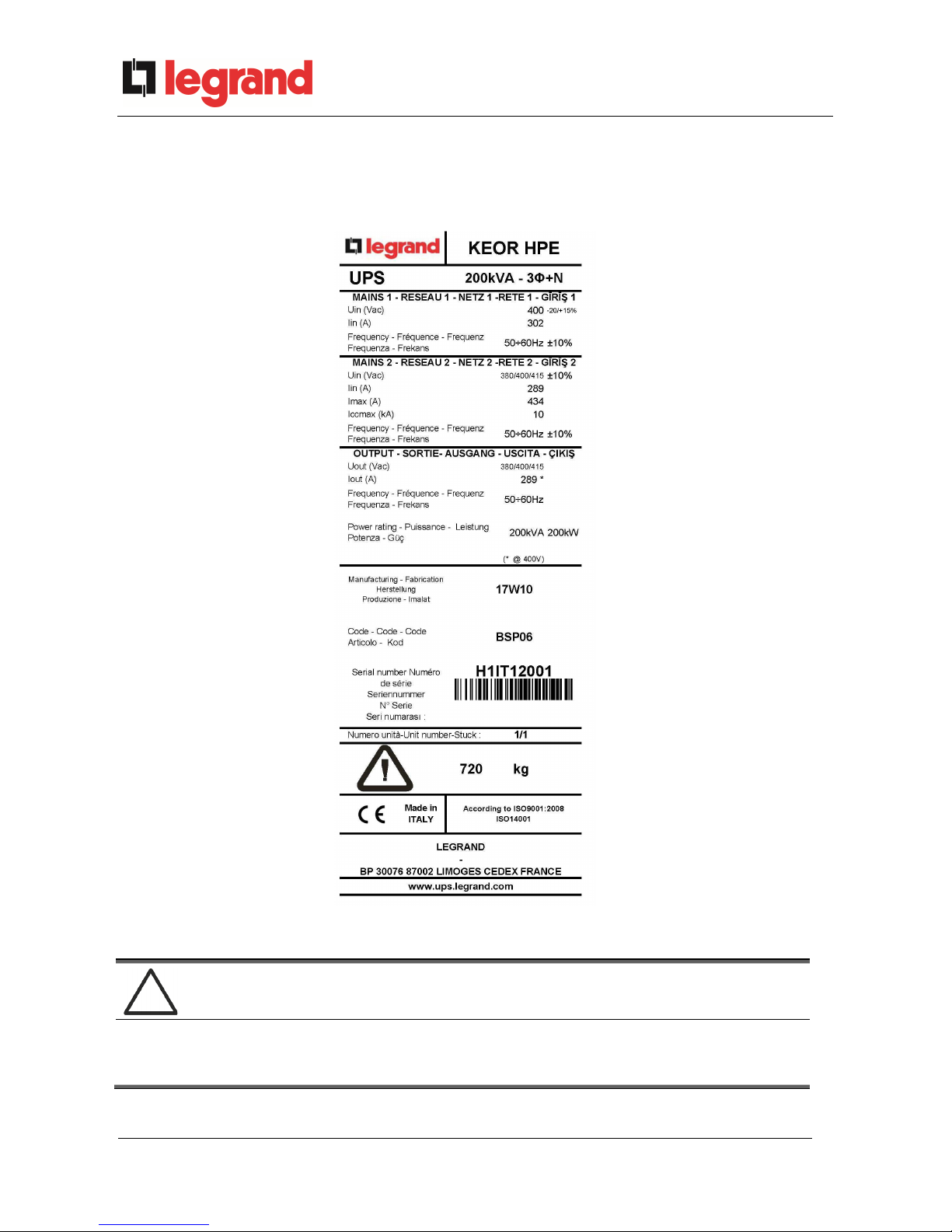
2.2 UPS RATING PLATE
The KEOR UPS 200 kVA is provided with an identification plate containing the operation
ratings. The plate is fixed in the inside of the UPS door.
Picture 1 – Rating plate of KEOR HPE 200 kVA
Check the technical characteristics
Before carrying out any installation or start-up operation on the UPS, make sure its
technical characteristics are compatible with the AC supply line and with the output
loads.
Installation and start-up of KEOR HPE UPS 200 kVA
Installazione e avviamento KEOR HPE UPS 200 kVA
OMP06144 REV. A
13
2.3 SPECIAL SAFETY WARNINGS
2.3.1 General warnings
The UPS is provided with various stickers with indications regarding specific dangers. These
stickers must be always well visible and replaced in case they are damaged.
The present documentation must be always available in proximity to the device. In case of loss
we recommend to request a copy to the manufacturer, whose details are available in the
“Contacts” section.
2.3.2 Personnel
Any operation on the UPS must be carried out by qualified personnel.
By qualified and trained person we mean someone skilled in assembling, installing, starting up
and checking the correct operation of the product, who is qualified to perform his/her job and
has entirely read and understood this manual, especially the part regarding safety. Such training
and qualification shall be considered as such, only when certified by the manufacturer.
2.3.3 Transport and handling
Avoid bending or deforming the components and altering the insulation distances while
transporting and handling the product.
Undistributed weight
The weight of the UPS is not uniformly distributed. Pay attention when lifting.
Please inspect the device before installing it. In case any damage is noticed from the conditions
of the package and/or from the outside appearance of the equipment, contact the shipping
company or your dealer immediately. The damage statement must be made within 6 days from
receipt of the product and must be notified to the shipping carrier directly. Should the product
need to be returned to the manufacturer, please use the original package.
Injury hazard due to mechanical damage
Mechanical damage to the electrical components constitutes a serious danger to
persons and property. In case of doubt regarding the non-integrity of the package or
of the product contained therein, contact the manufacturer before carrying out the
installation and/or the start-up.

Installation and start-up of KEOR HPE UPS 200 kVA
Installazione e avviamento KEOR HPE UPS 200 kVA
14 OMP06144 REV. A
2.3.4 Installation
The product must be installed in strict compliance with the instructions contained in the
technical back-up documentation, including the present safety instructions. In particular, the
following points must be taken into account:
The product must be placed on a base suitable to carry its weight and to ensure its
vertical position;
The UPS must be installed in a room with restricted access, according to standard
CEI EN62040-1;
Never install the equipment near liquids or in an excessively damp environment;
Never let a liquid or foreign body penetrate inside the device;
Never block the ventilation grates;
Never expose the device to direct sunlight or place it near a source of heat.
Special environmental conditions
The UPS is designed for normal climatic and environmental operating conditions as
defined in the technical specification: altitude, ambient operating temperature,
relative humidity and environmental transport and storage conditions. It is necessary
to implement specific protective measures in case of unusual conditions:
harmful smoke, dust, abrasive dust;
humidity, vapour, salt air, bad weather or dripping;
explosive dust and gas mixture;
extreme temperature variations;
bad ventilation;
conductive or radiant heat from other sources;
strong electromagnetic fields;
radioactive levels higher than those of the natural environment;
fungus, insects, vermin.
Use authorized personnel only
All transport, installation and start-up operations must be carried out by qualified and
trained personnel.
The installation of the UPS must be carried out by authorized personnel, in
compliance with national and local regulations.
Installation and start-up of KEOR HPE UPS 200 kVA
Installazione e avviamento KEOR HPE UPS 200 kVA
OMP06144 REV. A
15
Do not modify the device
Do not modify the device in any way: this may result in damage to the equipment
itself as well as to objects and persons. Maintenance and repair must be carried out
by authorized personnel only. Contact the manufacturer for details of the nearest
service centre.
2.3.5 Electrical connection
The UPS connection to the AC power must be carried out in compliance with the current
regulations.
Make sure the indications specified on the identification plate correspond to the AC power
system and to the actual electrical consumption of all of the equipment connected.
Check the conformity to the Standards
The UPS must be installed in compliance with the standards in force in the country of
installation.
IT system
The UPS is also designed to be connected to an IT power distribution system.
All the electrical connections must be carried out by authorized personnel. Before connecting
the device make sure that:
the connection cable to the AC line is properly protected;
the nominal voltages, the frequency and the phase rotation of the AC supply are
respected;
the polarities of the DC cables coming from the battery have been checked;
no leakage current to earth is present.
The device is connected to the following voltage supplies:
DC battery voltage;
AC mains voltage;
AC bypass voltage.
Installation and start-up of KEOR HPE UPS 200 kVA
Installazione e avviamento KEOR HPE UPS 200 kVA
16 OMP06144 REV. A
Injury hazard due to electric shock!
The device is subject to high voltages, thus all safety instructions must be
scrupulously adhered to before performing any operation on the UPS:
Isolate the battery via DC circuit breakers before connecting it to the UPS;
Connect the ground cable to the relevant bar before carrying out any other
connection inside the device.
Injury hazard due to electric shock!
If primary power isolators are installed in an area other than the UPS one, you must
stick the following warning label on the UPS. “ISOLATE THE UNINTERRUPTIBLE
POWER SUPPLY (UPS) BEFORE WORKING ON THIS CIRCUIT”
2.3.6 Operation
The installations to which the UPS systems belong must comply with all the current safety
standards (technical equipment and accident-prevention regulations). The device can be
started, operated and disconnected only by authorized personnel.
The settings can only be changed using the original interface software.
Injury hazard due to electric shock!
During operation, the UPS converts power characterized by high voltages and
currents.
All the doors and the covers must remain closed.
Injury hazard due to contact with toxic substances
The battery supplied with the UPS contains small amounts of toxic materials. To
avoid accidents, the directives listed below must be observed:
Never operate the UPS if the ambient temperature and relative humidity are
higher than the levels specified in the technical documentation.
Never burn the battery (risk of explosion).
Do not attempt to open the battery (the electrolyte is dangerous for the eyes
and skin).
Comply with all applicable regulations for the disposal of the battery.
Installation and start-up of KEOR HPE UPS 200 kVA
Installazione e avviamento KEOR HPE UPS 200 kVA
OMP06144 REV. A
17
2.3.7 Maintenance
Service and repairs must be carried out by skilled and authorized personnel. Before carrying out
any maintenance operation, the UPS must be disconnected from AC and DC supply sources.
The device is provided with internal isolators which allow to isolate the internal power circuits.
However the voltages of the supply sources are present on the terminals. To isolate the device
completely, provide external circuit breakers on the lines.
The device contains dangerous voltages even after shutdown and disconnection from the
supply sources, due to the internal capacitors which discharge slowly. Thus we recommend to
wait at least 5 minutes before opening the device doors.
Injury hazard due to electric shock!
Any operation must be carried out only when voltage is absent and in compliance
with safety directives.
Make sure the battery circuit breaker that may be placed near the battery has
been opened.
Isolate the device completely by operating the external circuit breakers.
Wait at least 5 minutes in order to allow the capacitors to discharge.
After switching off and disconnecting the device there still might be very hot components
(magnetic parts, heat sinks); therefore we recommend to use protective gloves.
High temperature of components
It is strongly recommended to use protective gloves due to the high temperatures that
may be reached during the operation.

Installation and start-up of KEOR HPE UPS 200 kVA
Installazione e avviamento KEOR HPE UPS 200 kVA
18 OMP06144 REV. A
2.3.8 Storage
If the product is stored prior to installation, it should remain stored in its original package in a dry
place with a temperature ranging from -10°C to +45°C.
Special environmental conditions
It is necessary to implement specific protective measures in case of unusual
environmental conditions:
harmful smoke, dust, abrasive dust;
humidity, vapour, salt air, bad weather or dripping;
explosive dust and gas mixture;
extreme temperature variations;
bad ventilation;
conductive or radiant heat from other sources;
fungus, insects, vermin.
2.4 ENVIRONMENTAL PROTECTION
2.4.1 ISO 14001 certification
Legrand is particularly sensitive to the environmental impact of its products. That is why the
UPS has been manufactured with cutting-edge eco-design criteria (ISO 14001 certification).
Special care was taken in using fully recyclable materials and in reducing the amounts of raw
materials used.
2.4.2 Recycling of packing materials
Packing materials must be recycled or disposed of in compliance with applicable local and
national laws and regulations.
2.4.3 Device disposal
At the end of their product life, the materials composing the device must be recycled or
disposed of in compliance with the current local and national laws and regulations.
Installation and start-up of KEOR HPE UPS 200 kVA
Installazione e avviamento KEOR HPE UPS 200 kVA
OMP06144 REV. A
19
3 INSTALLATION
3.1 RECEIPT OF THE UPS
Please inspect the device before installing it. In case any damage is noticed from the conditions
of the package and/or from the outside appearance of the equipment, contact the shipping
company or your dealer immediately. The damage statement must be made within 6 days from
receipt of the product and must be notified to the shipping carrier directly. Should the product
need to be returned to the manufacturer, please use the original package.
Danger to persons due to transport damages
Mechanical damage to the electrical components constitutes a serious danger to
persons and property. In case of doubt regarding the non-integrity of the package or
of the product contained therein, contact the manufacturer before carrying out the
installation and/or the start-up.
3.1.1 Storage
The package normally ensures protection from humidity and possible damages during transport.
Do not store the UPS outdoor.
Risk of damage due to inappropriate storage
For the environmental storage conditions, refer to the indications given for the
installation of the device.
The device must only be stored in rooms protected from dust and humidity.
The device cannot be stored outdoor.
Installation and start-up of KEOR HPE UPS 200 kVA
Installazione e avviamento KEOR HPE UPS 200 kVA
20 OMP06144 REV. A
3.2 HANDLING OF THE UPS
The UPS is packed on a pallet. It is handled from the transport vehicle to the installation (or
storage) place via a fork lift.
The device has a heavy weight
Avoid turnover during the transport of the UPS.
Cabinets must always be handled in upright position.
During loading and unloading operations, always respect the indications
regarding the device barycentre marked on the package.
Before positioning the UPS, in order to avoid risks of turnover, it’s recommended to move the
system on the wood pallet on which the UPS is fixed. Before the positioning in the final location,
remove the UPS from the pallet.
To handle the UPS remove the lower rear and front, insert the forks of a fork lift. The UPS can
be handled from the front according to the available spaces, as shown by the following picture.
795
KEOR HPE
Picture 2 – Handling of the KEOR HPE UPS 200 kVA

Installation and start-up of KEOR HPE UPS 200 kVA
Installazione e avviamento KEOR HPE UPS 200 kVA
OMP06144 REV. A
21
3.3 POSITIONING AND INSTALLATION
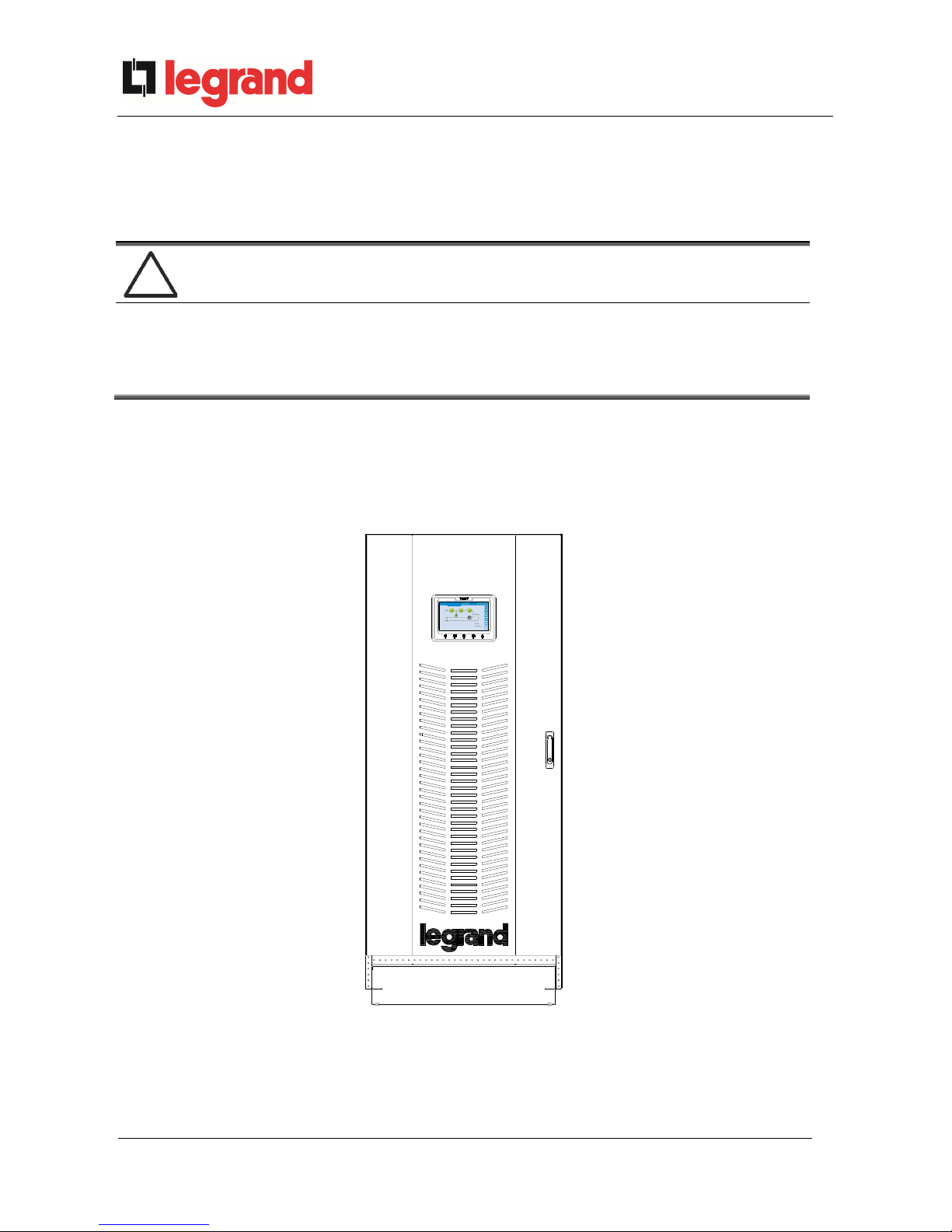
The KEOR HPE UPS 200 kVA must be installed indoor, in a clean and dry room, preferably
without dust or humidity infiltrations. For the environmental conditions in the place of installation,
in compliance with the current legislation, please refer to the “Overall dimensions, minimum
distances from the walls and ventilation” section.
Special environmental conditions
It is necessary to implement specific protective measures in case of unusual
environmental conditions:
harmful smoke, dust, abrasive dust;
humidity, vapour, salt air, bad weather or dripping;
explosive dust and gas mixture;
extreme temperature variations;
bad ventilation;
conductive or radiant heat from other sources;
fungus, insects, vermin.
Installation and start-up of KEOR HPE UPS 200 kVA
Installazione e avviamento KEOR HPE UPS 200 kVA
22 OMP06144 REV. A
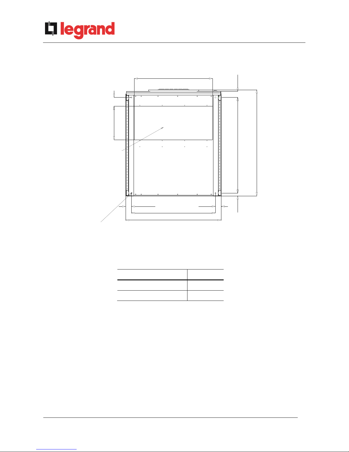
3.3.1 Base plan, static load and weights
855
750
854
24
947
53
79300
700
Ø
Ø
1
3
(
x
4
)
GLAND PLATE
52
52
Picture 3 – Base plan
The supporting base of the UPS must be designed to carry the UPS weight and to ensure its
steady and safe support.
Its carrying capacity must be adequate to the static load indicated in the table below.
Power (kVA) 200
Weight (kg) 720
Static load (kg/m2) 1120
Installation and start-up of KEOR HPE UPS 200 kVA
Installazione e avviamento KEOR HPE UPS 200 kVA
OMP06144 REV. A
23
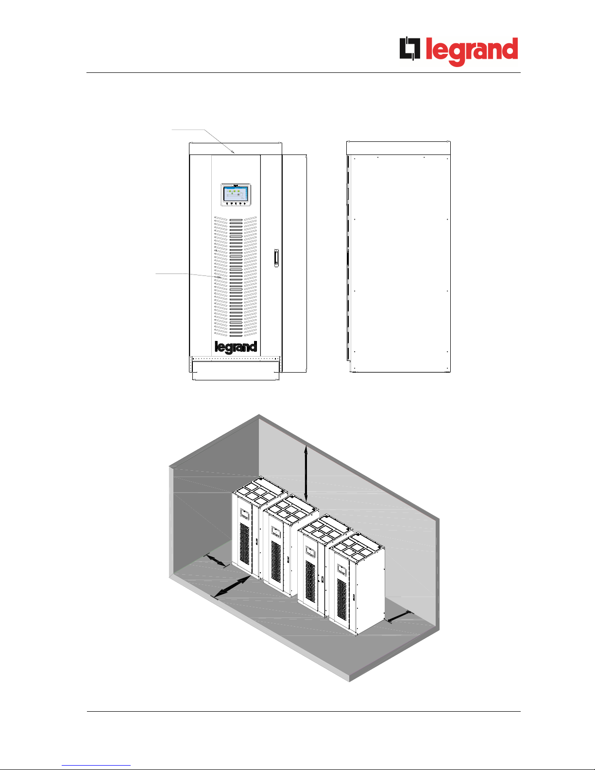
3.3.2 Overall dimensions, clearances and ventilation
850
1976
INLET AIR
OPENINGS
OUTLET AIR
OPENINGS
953
795
KEOR HPE
Picture 4 – Overall dimensions
c
B
D
A
Picture 5 – Clearances
Installation and start-up of KEOR HPE UPS 200 kVA
Installazione e avviamento KEOR HPE UPS 200 kVA
24 OMP06144 REV. A
The UPS must be so installed as to ensure its serviceability and to allow a correct air flow as
much as possible.
With regard to the minimum distances from the walls, for all of the UPS sizes the same
installation conditions apply as indicated in the table below.
A (mm) B (mm) C (mm) D (mm)
Recommended clearances
50 1200 50
600
Minimum clearances 0 1200 0
400
The table below shows the air volume required for an optimal ventilation and cooling of the
UPS.
Power (kVA) 60
Air volume (m3/h) 1800

Installation and start-up of KEOR HPE UPS 200 kVA
Installazione e avviamento KEOR HPE UPS 200 kVA
OMP06144 REV. A
25
3.3.3 Environmental installation conditions
The air is classified by the EN 60721-3-3 standard (Classification of environmental parameters
and their severities – Stationary use at weather-protected locations) based on climatic and
biological conditions as well as on mechanically and chemically active substances.
Therefore the place of installation must meet specific requirements to ensure compliance with
the conditions for which the UPS was designed.
Climatic conditions according to the technical specification of KEOR HPE 200 kVA
Environmental parameter
Minimum operating temperature (°C)
– 10
Maximum operating temperature (°C)
+ 40
Minimum relative humidity (%)
5
Maximum relative humidity (%)
95
Condensation
NO
Rainfall with wind (rain, snow, hail, etc.)
NO
Water with an origin other than rain
NO
Ice formation
NO
Classification of biological conditions (EN 60721-3-3)
Environmental
parameter
Class
3B1
3B2
3B3
a)
Flora
NO
Presence of mildew, fungus,
etc.
Presence of mildew, fungus,
etc.
b)
Fauna
NO
Presence of rodents and
other animals that are
harmful to products,
excluding termites
Presence of rodents and
other animals that are
harmful to products,
including termites
Classification of mechanically active substances (EN 60721-3-3)
Environmental parameter
Class
3S1
3S2
3S3
3S4
a)
Sand [mg/m3]
No
30 300 3000
b)
Dust (suspension) [mg/m3]
0,01 0,2 0,4 4,0
c)
Dust (sedimentation) [mg/(m2·h)
0,4 1,5 15 40
Places where precautions have been taken to minimize the presence
of dust. Places away from dust sources
X
Places without any special precaution to minimize the presence of
sand or dust, however not in proximity to sand or dust sources
X
Places in proximity to sand or dust sources
X
Places in proximity to working processes that generate sand or dust,
or in geographic areas having a high proportion of sand brought by
the wind or of dust suspended in the air
X

Installation and start-up of KEOR HPE UPS 200 kVA
Installazione e avviamento KEOR HPE UPS 200 kVA
26 OMP06144 REV. A
Classification of chemically active substances (EN 60721-3-3)
Environmental parameter
Class
3C1R 3C1L 3C1 3C2 3C3 3C4
a)
Sea salt
No
No
No
Salt
fog
Salt
fog
Salt
fog
b)
Sulphur dioxide
[mg/m3]
0,01 0,1 0,1 1,0 10 40
c)
Hydrogen sulphide
[mg/m3]
0,0015 0,01 0,01 0,5 10 70
d)
Chlorine [mg/m3]
0,001 0,01 0,1 0,3 1,0 3,0
e)
H
ydrochloric acid
[mg/m3]
0,001 0,01 0,1 0,5 5,0 5,0
f)
H
ydrofluoric acid
[mg/m3]
0,001 0,003 0,003 0,03 2,0 2,0
g)
Ammonia [mg/m3]
0,03 0,3 0,3 3,0 35 175
h)
Ozone [mg/m3]
0,004 0,01 0,01 0,1 0,3 2,0
i)
Nitric oxide (expressed in equivalent values of
nitrogen dioxide) [mg/m3]
0,01 0,1 0,1 1,0 9,0 20
Places where atmosphere is strictly monitored and
regulated (“clean spaces” category)
X
Places where atmosphere is permanently
monitored
X
Places located in rural and urban
regions where
industrial activities are few and where traffic
is moderate
X
Places located in urban regions with industrial
activities and/or considerable traffic
X
Places in proximity to industrial sources with
chemical emissions
X
Places located in industrial installations.
Emissions of highly concentrated chemical
pollutants
X
The KEOR HPE UPS 200 kVA is designed to be installed in an environment that meets the
following classifications.
K Climatic conditions
In accordance with the technical
specification
B Biological conditions
3B1 (EN 60721-3-3)
C Chemically active substances
3C2 (EN 60721-3-3)
S Mechanically active substances
3S2 (EN 60721-3-3)
In the event that the environmental conditions of the installation room do not comply with the
specified requirements, additional precautions must be taken to reduce excessive values to the
specified limits.
Installation and start-up of KEOR HPE UPS 200 kVA
Installazione e avviamento KEOR HPE UPS 200 kVA
OMP06144 REV. A
27
3.4 POSITIONING AND CONNECTION OF THE BATTERIES
Risk of electric shock
A battery can present a risk for electrical shock and high short circuit current. The
following precautions should be observed when working on batteries:
a) Remove watches, rings or other metal objects;
b) Use tools with insulated handles;
c) Wear rubber gloves and boots;
d) Do not lay tools or metal parts on top of batteries;
e) Disconnect the charging source prior connecting or disconnecting battery
terminals;
f) Determine if battery is inadvertently grounded. If inadvertently grounded,
remove source from ground. Contact with any part of a grounded battery can
result in electrical shock. The likelihood of such shock can be reduced if
such grounds are removed during installation and maintenance (applicable
to equipment and remote battery supplies not having a grounded supply
circuit).
Follow the installation instructions
For battery installation please respect EN62040-1 strictly and follow the installation
manual of the UPS.
To obtain the battery life indicated by the battery manufacturer, the operating
temperature must remain between 0 and 25 °C. However, although the battery can
operate up to 40°C, there will be a significant reduction of the battery life.
To avoid the formation of any kind of potentially explosive hydrogen and oxygen
mixture, suitable ventilation must be provided where the battery is installed (see
EN62040-1 annex M).
For the materials installed in France, the rule stated by NFC 15-100 article 554.2
must be applied: the volume of the renewed air has to be at least 0,05 NI m3 per
hour, where N is the number of the elements inside the battery and I is maximum
current of the rectifier.
The batteries can either be internal or external; it is recommended to install them when the UPS
is capable of charging them. Please remember that, if the battery is not charged for periods over
2-3 months it can be subject to irreparable damage.
Auxiliary contact of the external battery switch
For a correct operation of the UPS it is advisable to connect the auxiliary contact of
the external battery switch to the terminals X10-9/10.
 Loading...