

Page 1

Installation and start-up of KEOR HPE UPS 60÷160 kVA
Installation et démarrage de l’ASI KEOR HPE 60÷160 kVA
Installazione e avviamento KEOR HPE UPS 60÷160 kVA
OML46086 REV. C
1
INSTALLATION AND START-UP OF KEOR
HPE UPS 60÷160 KVA
INSTALLATION ET DÉMARRAGE DE L’ASI
KEOR HPE 60÷160 KVA
INSTALLAZIONE E AVVIAMENTO UPS KEOR
HPE 60÷160 KVA
Rev.
Descrizione
Description
Data
Date
Emesso
Issued
Approvato
Approved
Lingua
Language
Pagina
Page
di Pag.
of Pag.
C VR 31-17 14.02.17 R. Soldani G. Senesi
E/I 1 141
Codice / Code
OML46086
Page 2

Installation and start-up of KEOR HPE UPS 60÷160 kVA
Installation et démarrage de l’ASI KEOR HPE 60÷160 kVA
Installazione e avviamento KEOR HPE UPS 60÷160 kVA
2 OML46086 REV. C
Index / Indice
ENGLISH LANGUAGE .................................................................................... 9
1 SCOPE .................................................................................................... 11
2 SAFETY RULES AND WARNINGS ........................................................ 12
2.1 USE OF THE UPS ........................................................................................................... 12
2.2 UPS RATING PLATE ...................................................................................................... 13
2.3 SPECIAL SAFETY WARNINGS ...................................................................................... 14
2.3.1 General warnings ................................................................................................... 14
2.3.2 Personnel ................................................................................................................ 14
2.3.3 Transport and handling.......................................................................................... 14
2.3.4 Installation .............................................................................................................. 15
2.3.5 Electrical connection ............................................................................................. 16
2.3.6 Operation ................................................................................................................ 17
2.3.7 Maintenance ............................................................................................................ 18
2.3.8 Storage .................................................................................................................... 19
2.4 ENVIRONMENTAL PROTECTION .................................................................................. 19
2.4.1 ISO 14001 certification ........................................................................................... 19
2.4.2 Recycling of packing materials ............................................................................. 19
2.4.3 Device disposal ...................................................................................................... 19
3 INSTALLATION ...................................................................................... 20
3.1 RECEIPT OF THE UPS ................................................................................................... 20
3.1.1 Storage .................................................................................................................... 20
3.2 HANDLING OF THE UPS ................................................................................................ 21
3.3 POSITIONING AND INSTALLATION .............................................................................. 22
3.3.1 Base plan, static load and weights ....................................................................... 23
3.3.2 Overall dimensions, clearances and ventilation .................................................. 24
3.3.3 Environmental installation conditions .................................................................. 26
3.4 POSITIONING AND CONNECTION OF THE BATTERIES ............................................. 28
4 ELECTRICAL CONNECTION ................................................................. 29
4.1 CONNECTION OF THE POWER CABLES ..................................................................... 30
4.2 BACKFEED PROTECTION DEVICE ............................................................................... 32
4.3 TERMINAL BOARDS ...................................................................................................... 34
4.4 BATTERY ........................................................................................................................ 36
Page 3

Installation and start-up of KEOR HPE UPS 60÷160 kVA
Installation et démarrage de l’ASI KEOR HPE 60÷160 kVA
Installazione e avviamento KEOR HPE UPS 60÷160 kVA
OML46086 REV. C
3
4.4.1 Battery connection and positioning ...................................................................... 37
4.4.1.1 7/9/11Ah 12V installation – KEOR HPE 60-80 kVA ............................................ 38
4.4.1.2 12/14Ah 12V battery installation – KEOR HPE 60-80 kVA ................................ 40
4.5 CONNECTION OF THE AUXILIARY CABLES ................................................................ 42
4.5.1 External manual bypass ......................................................................................... 42
4.5.2 NORMAL/BYPASS selector .................................................................................... 42
4.5.3 UPS output switch .................................................................................................. 42
4.5.4 Remote emergency power off (EPO) ..................................................................... 43
4.5.5 Battery auxiliary contact ........................................................................................ 43
4.5.6 Diesel Generator auxiliary contact ........................................................................ 43
4.6 SERIAL INTERFACES AND EXTERNAL CONNECTIONS ............................................. 43
4.7 RELAY CARD CONNECTION (OPTIONAL) .................................................................... 45
5 STARTUP AND SHUTDOWN ................................................................ 46
5.1 PRELIMINARY CHECKS ................................................................................................. 46
5.2 START-UP PROCEDURE ................................................................................................ 47
5.3 BASIC TROUBLESHOOTING ......................................................................................... 49
5.4 SHUT-DOWN PROCEDURE ............................................................................................ 49
5.5 SWITCHING PROCEDURE TO MANUAL BYPASS ........................................................ 50
5.6 RESTART FROM MANUAL BYPASS ............................................................................. 51
LANGUE FRANÇAIS .................................................................................... 53
1 PORTEE ................................................................................................. 55
2 RÈGLES DE SECURITE ET AVERTISSEMENTS ................................. 56
2.1
UTILISATION DE L'ASI ................................................................................................... 56
2.2
VALEURS NOMINALES DE L’ASI .................................................................................. 57
2.3
AVERTISSEMENTS SPÉCIFIQUES RELATIFS À LA SÉCURITÉ .................................. 58
2.3.1 Avertissements généraux ....................................................................................... 58
2.3.2 Personnel ................................................................................................................ 58
2.3.3 Transport et manutention ....................................................................................... 58
2.3.4 Installation ............................................................................................................... 59
2.3.5 Raccordement électrique ....................................................................................... 60
2.3.6 Fonctionnement ...................................................................................................... 61
2.3.7 Maintenance ............................................................................................................ 62
2.3.8 Stockage .................................................................................................................. 63
2.4
PROTECTION DE L'ENVIRONNEMENT ......................................................................... 63
Page 4

Installation and start-up of KEOR HPE UPS 60÷160 kVA
Installation et démarrage de l’ASI KEOR HPE 60÷160 kVA
Installazione e avviamento KEOR HPE UPS 60÷160 kVA
4 OML46086 REV. C
2.4.1 Certification ISO 14001 ........................................................................................... 63
2.4.2 Recyclage des matériaux d'emballage .................................................................. 63
2.4.3 Mise au rebut de l'appareil ..................................................................................... 63
3 INSTALLATION ...................................................................................... 64
3.1
RECEPTION DE L'ASI .................................................................................................... 64
3.1.1 Stockage ................................................................................................................. 64
3.2
MANUTENTION DE L'ASI ............................................................................................... 65
3.3
POSITIONNEMENT ET INSTALLATION ......................................................................... 66
3.3.1 Plan de base, charge statique et poids ................................................................. 67
3.3.2 Dimensions totales, dégagement minimum et ventilation ................................... 68
3.3.3 Conditions environnementales d'installation ....................................................... 70
3.4
MONTAGE ET CONNEXION DES BATTERIES .............................................................. 72
4 RACCORDEMENT ELECTRIQUE .......................................................... 73
4.1
RACCORDEMENT DES CÂBLES D'ALIMENTATION .................................................... 74
4.2
DISPOSITIF DE PROTECTION CONTRE LE BACKFEED ............................................. 76
4.3
BORNIERS ...................................................................................................................... 77
4.4
BATTERIES ..................................................................................................................... 80
4.4.1 Emplacement et conexion des batteries ............................................................... 81
4.4.1.1 7/9/11Ah 12V installation – KEOR HPE 60-80 kVA ............................................ 82
4.4.1.2 12/14Ah 12V battery installation – KEOR HPE 60-80 kVA ................................ 84
4.5
RACCORDEMENT DES CABLES AUXILIAIRES............................................................ 86
4.5.1 By-pass manuel externe......................................................................................... 86
4.5.2 Commande externe NORMAL/BYPASS ................................................................ 86
4.5.3 Interrupteur de sortie ASI ....................................................................................... 86
4.5.4 Bouton d’arrêt d’urgence à distance (EPO) .......................................................... 87
4.5.5 Contact auxiliaire de batterie ................................................................................. 87
4.5.6 Contact auxiliaire du Groupe electrogène ............................................................ 87
4.6
INTERFACES DE SERIE ET CONNEXIONS INTERNES ................................................ 87
4.7
CONNEXION DE LA CARTE RELAIS (OPTIONNEL) ..................................................... 89
5 DEMARRAGE ET ARRET ...................................................................... 90
5.1
VERIFICATIONS PRELIMINAIRES ................................................................................. 90
5.2
PROCEDURE DE DEMARRAGE .................................................................................... 91
5.3
DÉPANNAGE DE BASE.................................................................................................. 93
5.4
PROCEDURE D’ARRET .................................................................................................. 94
Page 5

Installation and start-up of KEOR HPE UPS 60÷160 kVA
Installation et démarrage de l’ASI KEOR HPE 60÷160 kVA
Installazione e avviamento KEOR HPE UPS 60÷160 kVA
OML46086 REV. C
5
5.5
PROCÉDURE DE BASCULEMENT EN BY-PASS MANUEL .......................................... 95
5.6
REDEMARRAGE DEPUIS LE BY-PASS MANUEL ......................................................... 96
LINGUA ITALIANA ....................................................................................... 98
1 APPLICABILITA’ ................................................................................. 100
2 REGOLE E AVVERTENZE DI SICUREZZA......................................... 101
2.1 UTILIZZO DEL DISPOSITIVO ........................................................................................ 101
2.2 DATI NOMINALI UPS .................................................................................................... 102
2.3 INDICAZIONI PARTICOLARI SULLA SICUREZZA ....................................................... 103
2.3.1 Avvertenze generali .............................................................................................. 103
2.3.2 Personale............................................................................................................... 103
2.3.3 Trasporto e movimentazione ............................................................................... 103
2.3.4 Installazione .......................................................................................................... 104
2.3.5 Collegamento elettrico ......................................................................................... 105
2.3.6 Funzionamento ..................................................................................................... 106
2.3.7 Manutenzione ........................................................................................................ 107
2.3.8 Immagazzinamento ............................................................................................... 108
2.4 TUTELA AMBIENTALE ................................................................................................. 108
2.4.1 Certificazione ISO 14001 ...................................................................................... 108
2.4.2 Riciclaggio dei materiali di imballaggio .............................................................. 108
2.4.3 Smaltimento del dispositivo ................................................................................. 108
3 INSTALLAZIONE ................................................................................. 109
3.1 RICEZIONE DELL’UPS ................................................................................................. 109
3.1.1 Immagazzinamento ............................................................................................... 109
3.2 MOVIMENTAZIONE DELL’UPS .................................................................................... 110
3.3 POSIZIONAMENTO ED INSTALLAZIONE .................................................................... 111
3.3.1 Pianta di base, carico statico e pesi .................................................................... 112
3.3.2 Dimensioni di ingombro, distanze minime dalle pareti e ventilazione .............. 113
3.3.3 Condizioni ambientali di installazione ................................................................. 115
3.4 POSIZIONAMENTO E ALLACCIAMENTO BATTERIE ................................................. 117
4 ALLACCIAMENTO ELETTRICO ......................................................... 118
4.1 COLLEGAMENTO CONDUTTORI DI POTENZA .......................................................... 119
4.2 PROTEZIONE CONTRO IL RITORNO DI TENSIONE (BACKFEED) ............................ 121
4.3 MORSETTIERE .............................................................................................................. 123
4.4 INSTALLAZIONE BATTERIE INTERNE ........................................................................ 125
Page 6

Installation and start-up of KEOR HPE UPS 60÷160 kVA
Installation et démarrage de l’ASI KEOR HPE 60÷160 kVA
Installazione e avviamento KEOR HPE UPS 60÷160 kVA
6 OML46086 REV. C
4.4.1 Connessione batterie interne .............................................................................. 126
4.4.1.1 Installazione batterie 7/9/11Ah 12V – KEOR HPE 60-80kVA .......................... 127
4.4.1.2 Installazione batterie 12/14Ah 12V – KEOR HPE 60-80kVA ........................... 129
4.5 COLLEGAMENTO CAVI AUSILIARI ............................................................................. 131
4.5.1 Bypass manuale esterno ..................................................................................... 131
4.5.2 Selettore NORMALE/BYPASS esterno ................................................................ 131
4.5.3 Contatto ausiliario sezionatore uscita UPS esterno .......................................... 131
4.5.4 Spegnimento remoto (EPO) ................................................................................. 132
4.5.5 Contatto ausiliario sezionatore di batteria .......................................................... 132
4.5.6 Contatto ausiliario Generatore Diesel ................................................................. 132
4.6 INTERFACCE SERIALI ................................................................................................. 132
4.7 COLLEGAMENTO SCHEDA RELÈ (OPZIONALE) ...................................................... 134
5 AVVIAMENTO E ARRESTO ................................................................. 135
5.1 VERIFICHE PRELIMINARI ............................................................................................ 135
5.2 PROCEDURA DI AVVIAMENTO ................................................................................... 136
5.3 RICERCA GUASTI DI BASE ......................................................................................... 138
5.4 PROCEDURA DI ARRESTO ......................................................................................... 138
5.5 PROCEDURA DI TRASFERIMENTO SU BYPASS MANUALE .................................... 139
5.6 RIAVVIO DA BYPASS MANUALE ................................................................................ 140
Page 7

Installation and start-up of KEOR HPE UPS 60÷160 kVA
Installation et démarrage de l’ASI KEOR HPE 60÷160 kVA
Installazione e avviamento KEOR HPE UPS 60÷160 kVA
OML46086 REV. C
7
Index of pictures / Indice delle figure
Picture 1 – Rating plate of KEOR HPE 60÷160 kVA .......................................................................................... 13
Picture 2 – Handling of the KEOR HPE UPS 60÷160 kVA ................................................................................. 21
Picture 3 – Base plan .......................................................................................................................................... 23
Picture 4 – Overall dimensions ........................................................................................................................... 24
Picture 5 – Clearances ........................................................................................................................................ 24
Picture 6 – Single Line Diagram KEOR HPE 60-80kVA with connection to external device .............................. 32
Picture 6a – Single Line Diagram KEOR HPE 100kVA with connection to external device ............................... 33
Picture 6b – Single Line Diagram KEOR HPE 125-160kVA with connection to external device ........................ 33
Picture 7 – Terminal board KEOR HPE 60-80 kVA ............................................................................................ 34
Picture 8 – Terminal board KEOR HPE 100 kVA ............................................................................................... 34
Picture 8bis – Terminal board KEOR HPE 125÷160 kVA ................................................................................... 35
Picture 9 – Cabling of BCB fuse holder ............................................................................................................... 37
Picture 10 - Trays 7/9/11Ah 12V battery lateral view .......................................................................................... 38
Picture 11 – One raw 7/9/11Ah 12V battery top view ......................................................................................... 38
Picture 12- 7/9/11Ah 12V battery connection tray top view ............................................................................... 39
Picture 13- 7/9/11Ah 12V battery connection tray front view ............................................................................. 39
Picture 14 - Trays 12/14Ah 12V battery lateral view .......................................................................................... 40
Picture 15 – One raw 12/14Ah 12V battery top view .......................................................................................... 40
Picture 16- 12/14Ah 12V battery connection tray top view ................................................................................ 41
Picture 17-12/14Ah 12V battery connection tray front view ............................................................................... 41
Picture 18 – Auxiliary terminals of KEOR HPE 60÷160 kVA .............................................................................. 42
Picture 19 – Position of the serial interfaces of KEOR HPE 60÷160 kVA .......................................................... 43
Picture 20 – Relay card terminals ....................................................................................................................... 45
Illustration 1 – Plaque signalétique de l’ASI KERO HPE 60÷160 kVA ............................................................... 57
Illustration 2 – Manutention de l’ASI KEOR HPE 60÷160 kVA .......................................................................... 65
Illustration 3 – Plan de base ................................................................................................................................ 67
Illustration 4 – Dimensions globales .................................................................................................................... 68
Illustration 5 – Dégagement minimum ................................................................................................................. 68
Illustration 6 – Diagramme à une ligne KEOR HPE 60-80kVA avec connexion à un périphérique externe ...... 76
Illustration 6a – Diagramme à une ligne KEOR HPE 100kVA avec connexion à un périphérique externe ........ 77
Illustration 6b – Diagramme à une ligne KEOR HPE 125-160kVA avec connexion à un périphérique externe 77
Illustration 7 – Borniers KEOR HPE 60-80 kVA .................................................................................................. 78
Illustration 8 – Borniers KEOR HPE 100 kVA ..................................................................................................... 78
Illustration 8 bis – Borniers KEOR HPE 125-160 kVA ........................................................................................ 79
Illustration 9 – Câblage du porte-fusible BCB ..................................................................................................... 81
Page 8

Installation and start-up of KEOR HPE UPS 60÷160 kVA
Installation et démarrage de l’ASI KEOR HPE 60÷160 kVA
Installazione e avviamento KEOR HPE UPS 60÷160 kVA
8 OML46086 REV. C
Illustration 10 - Plateau 7/9/11Ah 12V vue latérale de la batterie ....................................................................... 82
Illustration 11 – Un range 7/9/11Ah 12V batterie vue de dessus....................................................................... 82
Illustration 12- 7/9/11Ah 12V batterie connexion vue dessus ............................................................................. 83
Illustration 13- 7/9/11Ah 12V batterie connexion vue frontale ............................................................................ 83
Illustration 14 - Plateau 12/14Ah 12V vue latérale de la batterie ........................................................................ 84
Illustration 15 – Un range 12/14Ah 12V batterie vue de dessus......................................................................... 84
Illustration 16- 12/14Ah 12V batterie connexion vue dessus .............................................................................. 85
Illustration 17-12/14Ah 12V batterie connexion vue frontale .............................................................................. 85
Illustration 18 – Bornes auxiliaires du KEOR HPE 60÷160 kVA ......................................................................... 86
Illustration 19 – Position des interfaces de série du KEORHPE 60÷160 kVA .................................................... 87
Illustration 20 – Bornes de la carte relais ............................................................................................................ 89
Figura 1 – Targhetta caratteristiche KEOR HPE 60÷160 kVA .......................................................................... 102
Figura 2 – Movimentazione UPS KEOR HPE 60÷160 kVA .............................................................................. 110
Figura 3 – Pianta di base .................................................................................................................................. 112
Figura 4 – Dimensioni di ingombro ................................................................................................................... 113
Figura 5 – Distanze di rispetto .......................................................................................................................... 113
Figura 6 – Schema unifilare KEOR HPE 60-80kVA con collegamento al dispositivo esterno ......................... 121
Figura 6a – Schema unifilare KEOR HPE 100kVA con collegamento al dispositivo esterno .......................... 122
Figura 6b – Schema unifilare KEOR HPE 125 - 160kVA con collegamento al dispositivo esterno ................ 122
Figura 7 – Morsettiera KEOR HPE 60-80 kVA ................................................................................................. 123
Figura 8 – Morsettiera KEOR HPE 100 kVA ..................................................................................................... 123
Figura 8bis – Morsettiera KEOR HPE 125-160 kVA ......................................................................................... 124
Figura 9 – Cablaggio portafusibili BCB ............................................................................................................. 126
Figura 10 – Vassoi batterie 7/9/11Ah 12V vista laterale .................................................................................. 127
Figura 11 – Fila singola batterie 7/9/11Ah 12V vista dall’alto ........................................................................... 127
Figura 12- 7/9/11Ah 12V connessione vassoi batterie vista dall’alto................................................................ 128
Figura 13- 7/9/11Ah 12V connessione vassoi batterie vista frontale ................................................................ 128
Figura 14 – Vassoi batterie 12/14Ah 12V vista laterale ................................................................................... 129
Figura 15 – Fila singola batterie 12/14Ah 12V vista dall’alto ........................................................................... 129
Figura 16 –12/14Ah 12V connessione vassoi batterie vista dall’alto ............................................................... 130
Figura 17- 12/14Ah 12V connessione vassoi batterie vista frontale ................................................................. 130
Figura 18 – Morsetti ausiliari KEOR HPE 60÷160 kVA .................................................................................... 131
Figura 19 – Posizione schede di interfaccia ..................................................................................................... 132
Figura 20 – Morsetti scheda relè ...................................................................................................................... 134
Page 9

Installation and start-up of KEOR HPE UPS 60÷160 kVA
Installation et démarrage de l’ASI KEOR HPE 60÷160 kVA
Installazione e avviamento KEOR HPE UPS 60÷160 kVA
OML46086 REV. C
9
ENGLISH LANGUAGE
Page 10

Installation and start-up of KEOR HPE UPS 60÷160 kVA
Installation et démarrage de l’ASI KEOR HPE 60÷160 kVA
Installazione e avviamento KEOR HPE UPS 60÷160 kVA
10 OML46086 REV. C
Page 11
Installation and start-up of KEOR HPE UPS 60÷160 kVA
Installation et démarrage de l’ASI KEOR HPE 60÷160 kVA
Installazione e avviamento KEOR HPE UPS 60÷160 kVA
OML46086 REV. C
11
1 SCOPE
The instructions contained in the operating manual are applicable to the UPS systems listed below.
BSL46 KEOR HPE 60 kVA
BSM46 KEOR HPE 80 kVA
BSK93 KEOR HPE 100 kVA
BSM47 KEOR HPE 125 kVA
BSM48 KEOR HPE 160 kVA
Storing documentation
This manual and any other supporting technical documentation relating to the product
must be stored and made accessible to personnel in the immediate vicinity of the
UPS.
Further information
In the event that the information provided in this manual is not sufficiently exhaustive,
please contact the manufacturer of the device, whose details are available in the
“Contacts” section.
Page 12
Installation and start-up of KEOR HPE UPS 60÷160 kVA
Installation et démarrage de l’ASI KEOR HPE 60÷160 kVA
Installazione e avviamento KEOR HPE UPS 60÷160 kVA
12 OML46086 REV. C
2 SAFETY RULES AND WARNINGS
2.1 USE OF THE UPS
Congratulations on choosing a product from Legrand for the safety of your equipment. To obtain the
best performance from your KEOR HPE 60÷160 kVA UPS system (Uninterruptible Power Supply),
we suggest that you take your time to read the following manual.
The purpose of this manual is to give a short description of the parts composing the UPS and to
guide the installer or the user through the installation of the unit in its using environment.
The installer or the user must read and correctly perform the instructions included in the present
manual, with particular reference to the requirements regarding safety, in compliance with the
current regulations.
Read the technical documentation
Before installing and using the device, make sure you have read and understood all
the instructions contained in the present manual and in the technical supporting
documentation.
Page 13
Installation and start-up of KEOR HPE UPS 60÷160 kVA
Installation et démarrage de l’ASI KEOR HPE 60÷160 kVA
Installazione e avviamento KEOR HPE UPS 60÷160 kVA
OML46086 REV. C
13
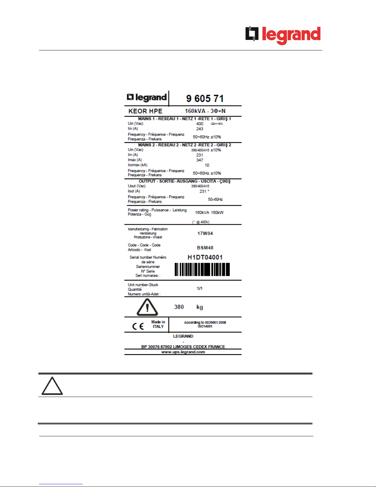
2.2 UPS RATING PLATE
The KEOR HPE UPS 60÷160 kVA is provided with an identification plate containing the operation
ratings. The plate is fixed in the inside of the UPS door.
Picture 1 – Rating plate of KEOR HPE 60÷160 kVA
Check the technical characteristics
Before carrying out any installation or start-up operation on the UPS, make sure its
technical characteristics are compatible with the AC supply line and with the output
loads.
Page 14
Installation and start-up of KEOR HPE UPS 60÷160 kVA
Installation et démarrage de l’ASI KEOR HPE 60÷160 kVA
Installazione e avviamento KEOR HPE UPS 60÷160 kVA
14 OML46086 REV. C
2.3 SPECIAL SAFETY WARNINGS
2.3.1 General warnings
The UPS is provided with various stickers with indications regarding specific dangers. These stickers
must be always well visible and replaced in case they are damaged.
The present documentation must be always available in proximity to the device. In case of loss we
recommend to request a copy to the manufacturer, whose details are available in the “Contacts”
section.
2.3.2 Personnel
Any operation on the UPS must be carried out by qualified personnel.
By qualified and trained person we mean someone skilled in assembling, installing, starting up and
checking the correct operation of the product, who is qualified to perform his/her job and has entirely
read and understood this manual, especially the part regarding safety. Such training and
qualification shall be considered as such, only when certified by the manufacturer.
2.3.3 Transport and handling
Avoid bending or deforming the components and altering the insulation distances while transporting
and handling the product.
Undistributed weight
The weight of the UPS is not uniformly distributed. Pay attention when lifting.
Please inspect the device before installing it. In case any damage is noticed from the conditions of
the package and/or from the outside appearance of the equipment, contact the shipping company or
your dealer immediately. The damage statement must be made within 6 days from receipt of the
product and must be notified to the shipping carrier directly. Should the product need to be returned
to the manufacturer, please use the original package.
Injury hazard due to mechanical damage
Mechanical damage to the electrical components constitutes a serious danger to
persons and property. In case of doubt regarding the non-integrity of the package or
of the product contained therein, contact the manufacturer before carrying out the
installation and/or the start-up.
Page 15
Installation and start-up of KEOR HPE UPS 60÷160 kVA
Installation et démarrage de l’ASI KEOR HPE 60÷160 kVA
Installazione e avviamento KEOR HPE UPS 60÷160 kVA
OML46086 REV. C
15
2.3.4 Installation
The product must be installed in strict compliance with the instructions contained in the technical
back-up documentation, including the present safety instructions. In particular, the following points
must be taken into account:
The product must be placed on a base suitable to carry its weight and to ensure its
vertical position;
The UPS must be installed in a room with restricted access, according to standard CEI
EN62040-1;
Never install the equipment near liquids or in an excessively damp environment;
Never let a liquid or foreign body penetrate inside the device;
Never block the ventilation grates;
Never expose the device to direct sunlight or place it near a source of heat.
Special environmental conditions
The UPS is designed for normal climatic and environmental operating conditions as
defined in the technical specification: altitude, ambient operating temperature,
relative humidity and environmental transport and storage conditions. It is necessary
to implement specific protective measures in case of unusual conditions:
harmful smoke, dust, abrasive dust;
humidity, vapour, salt air, bad weather or dripping;
explosive dust and gas mixture;
extreme temperature variations;
bad ventilation;
conductive or radiant heat from other sources;
strong electromagnetic fields;
radioactive levels higher than those of the natural environment;
fungus, insects, vermin.
Use authorized personnel only
All transport, installation and start-up operations must be carried out by qualified and
trained personnel.
The installation of the UPS must be carried out by authorized personnel, in
compliance with national and local regulations.
Page 16
Installation and start-up of KEOR HPE UPS 60÷160 kVA
Installation et démarrage de l’ASI KEOR HPE 60÷160 kVA
Installazione e avviamento KEOR HPE UPS 60÷160 kVA
16 OML46086 REV. C
Do not modify the device
Do not modify the device in any way: this may result in damage to the equipment
itself as well as to objects and persons. Maintenance and repair must be carried out
by authorized personnel only. Contact the manufacturer for details of the nearest
service centre.
2.3.5 Electrical connection
The UPS connection to the AC power must be carried out in compliance with the current regulations.
Make sure the indications specified on the identification plate correspond to the AC power system
and to the actual electrical consumption of all of the equipment connected.
Check the conformity to the Standards
The UPS must be installed in compliance with the standards in force in the country of
installation.
IT system
The UPS is also designed to be connected to an IT power distribution system.
All the electrical connections must be carried out by authorized personnel. Before connecting the
device make sure that:
the connection cable to the AC line is properly protected;
the nominal voltages, the frequency and the phase rotation of the AC supply are
respected;
the polarities of the DC cables coming from the battery have been checked;
no leakage current to earth is present.
The device is connected to the following voltage supplies:
DC battery voltage;
AC mains voltage;
AC bypass voltage.
Page 17
Installation and start-up of KEOR HPE UPS 60÷160 kVA
Installation et démarrage de l’ASI KEOR HPE 60÷160 kVA
Installazione e avviamento KEOR HPE UPS 60÷160 kVA
OML46086 REV. C
17
Injury hazard due to electric shock!
The device is subject to high voltages, thus all safety instructions must be
scrupulously adhered to before performing any operation on the UPS:
Isolate the battery via DC circuit breakers before connecting it to the UPS;
Connect the ground cable to the relevant bar before carrying out any other
connection inside the device.
Injury hazard due to electric shock!
If primary power isolators are installed in an area other than the UPS one, you must
stick the following warning label on the UPS. “ISOLATE THE UNINTERRUPTIBLE
POWER SUPPLY (UPS) BEFORE WORKING ON THIS CIRCUIT”
2.3.6 Operation
The installations to which the UPS systems belong must comply with all the current safety standards
(technical equipment and accident-prevention regulations). The device can be started, operated and
disconnected only by authorized personnel.
The settings can only be changed using the original interface software.
Injury hazard due to electric shock!
During operation, the UPS converts power characterized by high voltages and
currents.
All the doors and the covers must remain closed.
Injury hazard due to contact with toxic substances
The battery supplied with the UPS contains small amounts of toxic materials. To
avoid accidents, the directives listed below must be observed:
Never operate the UPS if the ambient temperature and relative humidity are
higher than the levels specified in the technical documentation.
Never burn the battery (risk of explosion).
Do not attempt to open the battery (the electrolyte is dangerous for the eyes
and skin).
Comply with all applicable regulations for the disposal of the battery.
Page 18
Installation and start-up of KEOR HPE UPS 60÷160 kVA
Installation et démarrage de l’ASI KEOR HPE 60÷160 kVA
Installazione e avviamento KEOR HPE UPS 60÷160 kVA
18 OML46086 REV. C
2.3.7 Maintenance
Service and repairs must be carried out by skilled and authorized personnel. Before carrying out any
maintenance operation, the UPS must be disconnected from AC and DC supply sources.
The device is provided with internal isolators which allow to isolate the internal power circuits.
However the voltages of the supply sources are present on the terminals. To isolate the device
completely, provide external circuit breakers on the lines.
The device contains dangerous voltages even after shutdown and disconnection from the supply
sources, due to the internal capacitors which discharge slowly. Thus we recommend to wait at least
5 minutes before opening the device doors.
Injury hazard due to electric shock!
Any operation must be carried out only when voltage is absent and in compliance
with safety directives.
Make sure the battery circuit breaker that may be placed near the battery has
been opened.
Isolate the device completely by operating the external circuit breakers.
Wait at least 5 minutes in order to allow the capacitors to discharge.
After switching off and disconnecting the device there still might be very hot components (magnetic
parts, heat sinks); therefore we recommend to use protective gloves.
High temperature of components
It is strongly recommended to use protective gloves due to the high temperatures that
may be reached during the operation.
Page 19
Installation and start-up of KEOR HPE UPS 60÷160 kVA
Installation et démarrage de l’ASI KEOR HPE 60÷160 kVA
Installazione e avviamento KEOR HPE UPS 60÷160 kVA
OML46086 REV. C
19
2.3.8 Storage
If the product is stored prior to installation, it should remain stored in its original package in a dry
place with a temperature ranging from -10°C to +45°C.
Special environmental conditions
It is necessary to implement specific protective measures in case of unusual
environmental conditions:
harmful smoke, dust, abrasive dust;
humidity, vapour, salt air, bad weather or dripping;
explosive dust and gas mixture;
extreme temperature variations;
bad ventilation;
conductive or radiant heat from other sources;
fungus, insects, vermin.
2.4 ENVIRONMENTAL PROTECTION
2.4.1 ISO 14001 certification
Legrand is particularly sensitive to the environmental impact of its products. That is why the UPS has
been manufactured with cutting-edge eco-design criteria (ISO 14001 certification).
Special care was taken in using fully recyclable materials and in reducing the amounts of raw
materials used.
2.4.2 Recycling of packing materials
Packing materials must be recycled or disposed of in compliance with applicable local and national
laws and regulations.
2.4.3 Device disposal
At the end of their product life, the materials composing the device must be recycled or disposed of
in compliance with the current local and national laws and regulations.
Page 20
Installation and start-up of KEOR HPE UPS 60÷160 kVA
Installation et démarrage de l’ASI KEOR HPE 60÷160 kVA
Installazione e avviamento KEOR HPE UPS 60÷160 kVA
20 OML46086 REV. C
3 INSTALLATION
3.1 RECEIPT OF THE UPS
Please inspect the device before installing it. In case any damage is noticed from the conditions of
the package and/or from the outside appearance of the equipment, contact the shipping company or
your dealer immediately. The damage statement must be made within 6 days from receipt of the
product and must be notified to the shipping carrier directly. Should the product need to be returned
to the manufacturer, please use the original package.
Danger to persons due to transport damages
Mechanical damage to the electrical components constitutes a serious danger to
persons and property. In case of doubt regarding the non-integrity of the package or
of the product contained therein, contact the manufacturer before carrying out the
installation and/or the start-up.
3.1.1 Storage
The package normally ensures protection from humidity and possible damages during transport. Do
not store the UPS outdoor.
Risk of damage due to inappropriate storage
For the environmental storage conditions, refer to the indications given for the
installation of the device.
The device must only be stored in rooms protected from dust and humidity.
The device cannot be stored outdoor.
Page 21
Installation and start-up of KEOR HPE UPS 60÷160 kVA
Installation et démarrage de l’ASI KEOR HPE 60÷160 kVA
Installazione e avviamento KEOR HPE UPS 60÷160 kVA
OML46086 REV. C
21
3.2 HANDLING OF THE UPS
The UPS is packed on a pallet. It is handled from the transport vehicle to the installation (or storage)
place via a fork lift.
The device has a heavy weight
Avoid turnover during the transport of the UPS.
Cabinets must always be handled in upright position.
During loading and unloading operations, always respect the indications
regarding the device barycentre marked on the package.
Before positioning the UPS, in order to avoid risks of turnover, it’s recommended to move the system
on the wood pallet on which the UPS is fixed. Before the positioning in the final location, remove the
UPS from the pallet.
To handle the UPS remove the lower front, rear and side panels and insert the forks of a fork lift. The
UPS can be handled both from the front and from the side according to the available spaces, as
shown by the following picture.
Picture 2 – Handling of the KEOR HPE UPS 60÷160 kVA
Page 22
Installation and start-up of KEOR HPE UPS 60÷160 kVA
Installation et démarrage de l’ASI KEOR HPE 60÷160 kVA
Installazione e avviamento KEOR HPE UPS 60÷160 kVA
22 OML46086 REV. C
3.3 POSITIONING AND INSTALLATION
The KEOR HPE UPS 60÷160 kVA must be installed indoor, in a clean and dry room, preferably
without dust or humidity infiltrations. For the environmental conditions in the place of installation, in
compliance with the current legislation, please refer to the “Overall dimensions, minimum distances
from the walls and ventilation” section.
Special environmental conditions
It is necessary to implement specific protective measures in case of unusual
environmental conditions:
harmful smoke, dust, abrasive dust;
humidity, vapour, salt air, bad weather or dripping;
explosive dust and gas mixture;
extreme temperature variations;
bad ventilation;
conductive or radiant heat from other sources;
fungus, insects, vermin.
Page 23
Installation and start-up of KEOR HPE UPS 60÷160 kVA
Installation et démarrage de l’ASI KEOR HPE 60÷160 kVA
Installazione e avviamento KEOR HPE UPS 60÷160 kVA
OML46086 REV. C
23
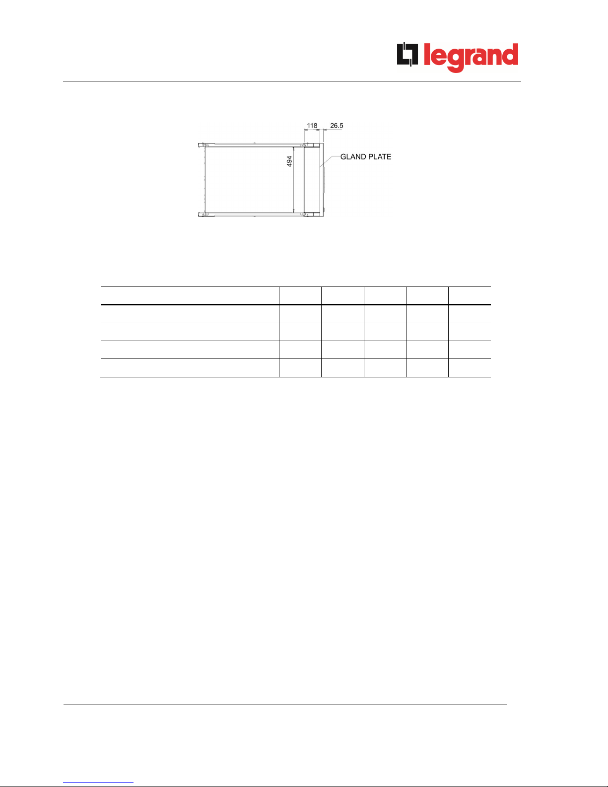
3.3.1 Base plan, static load and weights
Picture 3 – Base plan
The supporting base of the UPS must be designed to carry the UPS weight and to ensure its steady
and safe support.
Its carrying capacity must be adequate to the static loads indicated in the table below.
Power (kVA) 60 80 100 125 160
Weight w/o batteries (kg) 250 300 320 360 380
Static load w/o batteries (kg/m2) 490 590 630 710 750
Weight with batteries (kg) 800 850 - - Static load with batteries (kg/m2) 1570 1670 - - -
Page 24
Installation and start-up of KEOR HPE UPS 60÷160 kVA
Installation et démarrage de l’ASI KEOR HPE 60÷160 kVA
Installazione e avviamento KEOR HPE UPS 60÷160 kVA
24 OML46086 REV. C
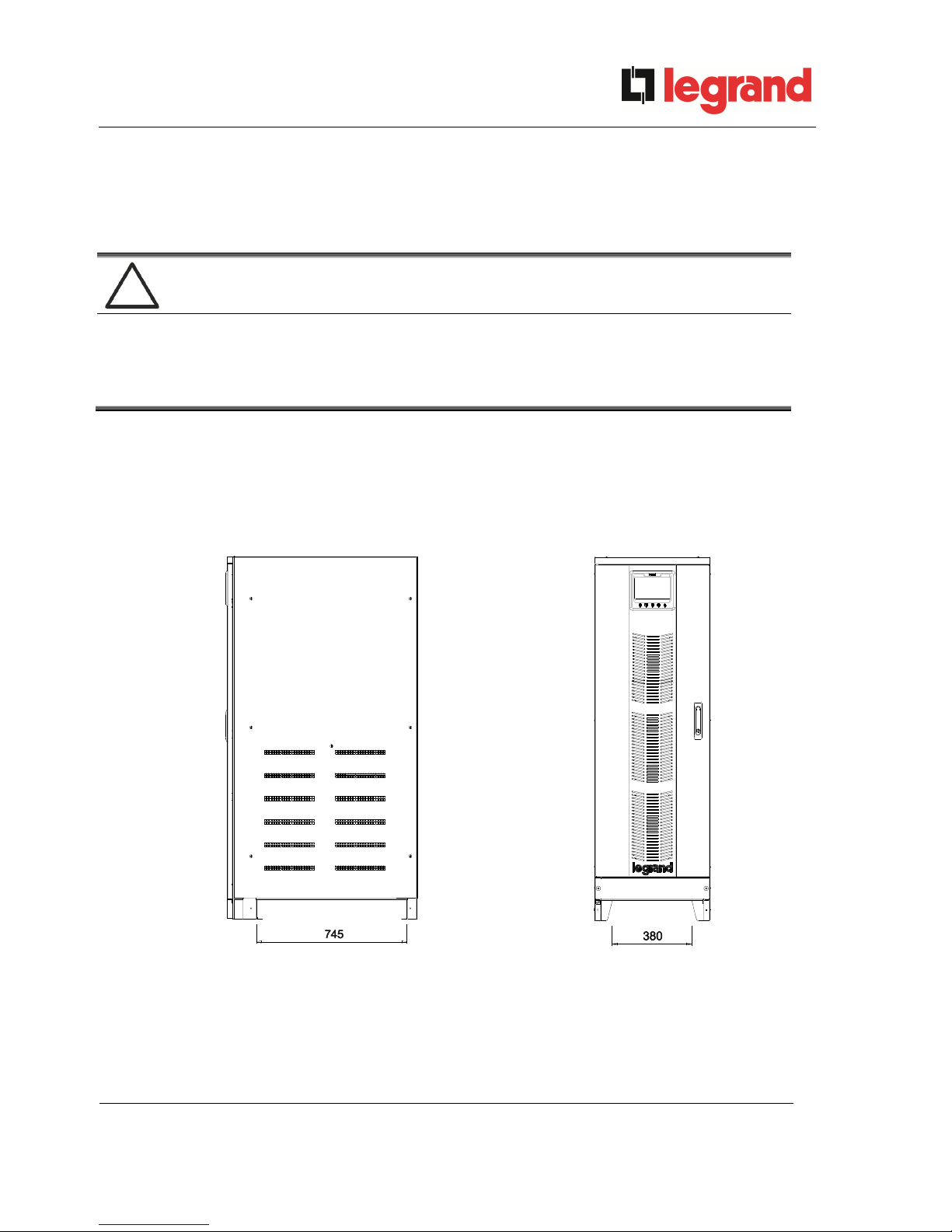
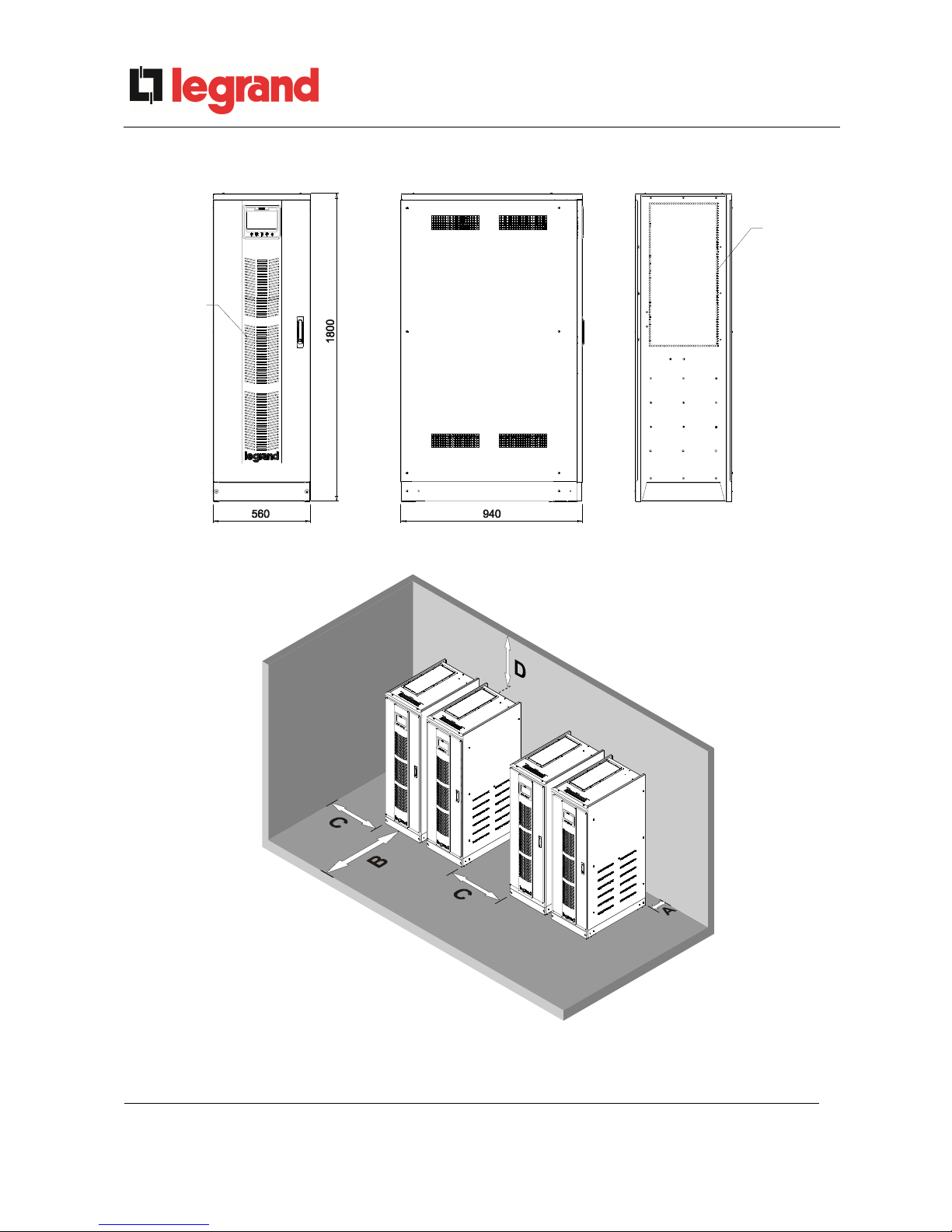
3.3.2 Overall dimensions, clearances and ventilation
INLET AIR
OPENINGS
OUTLET AIR
OPENINGS
Picture 4 – Overall dimensions
Picture 5 – Clearances
Page 25
Installation and start-up of KEOR HPE UPS 60÷160 kVA
Installation et démarrage de l’ASI KEOR HPE 60÷160 kVA
Installazione e avviamento KEOR HPE UPS 60÷160 kVA
OML46086 REV. C
25
The UPS must be so installed as to ensure its serviceability and to allow a correct air flow as much
as possible.
With regard to the minimum distances from the walls, for all of the UPS sizes the same installation
conditions apply as indicated in the table below.
- UPS with internal batteries
A (mm) B (mm) C (mm) D (mm)
Recommended clearances
50 1200 600
600
Minimum clearances 0 1200 600
400
- UPS with external battery cabinet
A (mm) B (mm) C (mm) D (mm)
Recommended clearances
50 1200 400
600
Minimum clearances 0 1200 0
400
The table below shows the air volume required for an optimal ventilation and cooling of the UPS.
Power (kVA) 60 80 100 125 160
Air volume (m3/h) 1000 1200 1200 1500 1500
Page 26
Installation and start-up of KEOR HPE UPS 60÷160 kVA
Installation et démarrage de l’ASI KEOR HPE 60÷160 kVA
Installazione e avviamento KEOR HPE UPS 60÷160 kVA
26 OML46086 REV. C
3.3.3 nvironmental installation conditions
The air is classified by the EN 60721-3-3 standard (Classification of environmental parameters and
their severities – Stationary use at weather-protected locations) based on climatic and biological
conditions as well as on mechanically and chemically active substances.
Therefore the place of installation must meet specific requirements to ensure compliance with the
conditions for which the UPS was designed.
Climatic conditions according to the technical specification of KEOR HPE 60÷160 kVA
Environmental parameter
Minimum operating temperature (°C)
– 10
Maximum operating temperature (°C)
+ 40
Minimum relative humidity (%)
5
Maximum relative humidity (%)
95
Condensation
NO
Rainfall with wind (rain, snow, hail, etc.)
NO
Water with an origin other than rain
NO
Ice formation
NO
Classification of biological conditions (EN 60721-3-3)
Environmental
parameter
Class
3B1
3B2
3B3
a)
Flora
NO
Presence of mildew, fungus,
etc.
Presence of mildew, fungus,
etc.
b)
Fauna
NO
Presence of rodents and
other animals that are
harmful to products,
excluding termites
Presence of rodents and
other animals that are
harmful to products,
including termites
Classification of mechanically active substances (EN 60721-3-3)
Environmental parameter
Class
3S1
3S2
3S3
3S4
a)
Sand [mg/m3]
No
30 300 3000
b)
Dust (suspension) [mg/m3]
0,01 0,2 0,4 4,0
c)
Dust (sedimentation) [mg/(m2·h)
0,4 1,5 15 40
Places where precautions have been taken to minimize the presence
of dust. Places away from dust sources
X
Places without any special precaution to minimize the presence of
sand or dust, however not in proximity to sand or dust sources
X
Places in proximity to sand or dust sources
X
Places in proximity to working processes that generate sand or dust,
or in geographic areas having a high proportion of sand brought by
the wind or of dust suspended in the air
X
Page 27

Installation and start-up of KEOR HPE UPS 60÷160 kVA
Installation et démarrage de l’ASI KEOR HPE 60÷160 kVA
Installazione e avviamento KEOR HPE UPS 60÷160 kVA
OML46086 REV. C
27
Classification of chemically active substances (EN 60721-3-3)
Environmental parameter
Class
3C1R 3C1L 3C1 3C2 3C3 3C4
a)
Sea salt
No
No
No
Salt
fog
Salt
fog
Salt
fog
b)
Sulphur dioxide
[mg/m3]
0,01 0,1 0,1 1,0 10 40
c)
Hydrogen sulphide
[mg/m3]
0,0015 0,01 0,01 0,5 10 70
d)
Chlorine [mg/m3]
0,001 0,01 0,1 0,3 1,0 3,0
e)
H
ydrochloric acid
[mg/m3]
0,001 0,01 0,1 0,5 5,0 5,0
f)
H
ydrofluoric acid
[mg/m3]
0,001 0,003 0,003 0,03 2,0 2,0
g)
Ammonia [mg/m3]
0,03 0,3 0,3 3,0 35 175
h)
Ozone [mg/m3]
0,004 0,01 0,01 0,1 0,3 2,0
i)
Nitric oxide (expressed in equivalent values of
nitrogen dioxide) [mg/m3]
0,01 0,1 0,1 1,0 9,0 20
Places where atmosphere is strictly monitored and
regulated (“clean spaces” category)
X
Places where atmosphere is permanently
monitored
X
Places located in rural and urban
regions where
industrial activities are few and where traffic
is moderate
X
Places located in urban regions with industrial
activities and/or considerable traffic
X
Places in proximity to industrial sources with
chemical emissions
X
Places located in industrial installations.
Emissions of highly concentrated chemical
pollutants
X
The KEOR HPE UPS 60÷160 kVA is designed to be installed in an environment that meets the
following classifications.
K Climatic conditions
In accordance with the technical
specification
B Biological conditions
3B1 (EN 60721-3-3)
C Chemically active substances
3C2 (EN 60721-3-3)
S Mechanically active substances
3S2 (EN 60721-3-3)
In the event that the environmental conditions of the installation room do not comply with the
specified requirements, additional precautions must be taken to reduce excessive values to the
specified limits.
Page 28
Installation and start-up of KEOR HPE UPS 60÷160 kVA
Installation et démarrage de l’ASI KEOR HPE 60÷160 kVA
Installazione e avviamento KEOR HPE UPS 60÷160 kVA
28 OML46086 REV. C
3.4 POSITIONING AND CONNECTION OF THE BATTERIES
Risk of electric shock
A battery can present a risk for electrical shock and high short circuit current. The
following precautions should be observed when working on batteries:
a) Remove watches, rings or other metal objects;
b) Use tools with insulated handles;
c) Wear rubber gloves and boots;
d) Do not lay tools or metal parts on top of batteries;
e) Disconnect the charging source prior connecting or disconnecting battery
terminals;
f) Determine if battery is inadvertently grounded. If inadvertently grounded,
remove source from ground. Contact with any part of a grounded battery can
result in electrical shock. The likelihood of such shock can be reduced if
such grounds are removed during installation and maintenance (applicable
to equipment and remote battery supplies not having a grounded supply
circuit).
Follow the installation instructions
For battery installation please respect EN62040-1 strictly and follow the installation
manual of the UPS.
To obtain the battery life indicated by the battery manufacturer, the operating
temperature must remain between 0 and 25 °C. However, although the battery can
operate up to 40°C, there will be a significant reduction of the battery life.
To avoid the formation of any kind of potentially explosive hydrogen and oxygen
mixture, suitable ventilation must be provided where the battery is installed (see
EN62040-1 annex M).
For the materials installed in France, the rule stated by NFC 15-100 article 554.2
must be applied: the volume of the renewed air has to be at least 0,05 NI m3 per
hour, where N is the number of the elements inside the battery and I is maximum
current of the rectifier.
The batteries can either be internal or external; it is recommended to install them when the UPS is
capable of charging them. Please remember that, if the battery is not charged for periods over 2-3
months it can be subject to irreparable damage.
Auxiliary contact of the external battery switch
For a correct operation of the UPS it is advisable to connect the auxiliary contact of
the external battery switch to the terminals X10-9/10.
Page 29
Installation and start-up of KEOR HPE UPS 60÷160 kVA
Installation et démarrage de l’ASI KEOR HPE 60÷160 kVA
Installazione e avviamento KEOR HPE UPS 60÷160 kVA
OML46086 REV. C
29
4 ELECTRICAL CONNECTION
The electrical connection is part of the work which is normally provided by the company that carries
out the product installation. For this reason, the UPS manufacturer shall not be held responsible for
any damages due to wrong connections.
Use qualified personnel only
All the operations related to the electric connection must be carried out by qualified
and trained personnel.
Work in compliance with the local standards
The installation of the KEOR HPE UPS 60÷160 kVA must be carried out in
compliance with national and local regulations.
Connection of ground cable
The grounding of the UPS via the relevant terminal is mandatory. It is strongly
recommended to connect the ground terminal as first terminal.
The electrical connection is part of the work which is normally provided by the company that carries
out the electrical installation and not by the UPS manufacturer. For this reason, the following
recommendations are only an indication, as the UPS manufacturer is not responsible for the
electrical installation. In any case we recommend to carry out the installation and the electrical input
and output connections in compliance with the local standards.
Cables must be selected bearing in mind technical, financial and safety aspects. The selection and
the sizing of cables from a technical viewpoint depend on the voltage, on the current absorbed by
the UPS, on the bypass line and on the batteries, on the ambient temperature and on the voltage
drop. Finally, the kind of cable laying must be taken into particular consideration.
For more explanations regarding the selection and the sizing of cables, please refer to the relevant
IEC standards, in particular to IEC 64-8 standard.
“Short-circuit currents” (very high currents with a short duration) and “overload currents” (relatively
high currents with a long duration) are among the main causes of cable damage. The protection
systems normally used to protect the cables are: thermal magnetic circuit breakers or fuses.
Protection circuit breakers must be selected according to the maximum short-circuit current (max
Isc) that is needed to determine the breaking power of automatic circuit breakers, and to the
minimum current (min Isc) that is needed to determine the maximum length of the line protected.
The protection against short-circuit must operate on the line before any thermal and electrothermal
effects of the overcurrents may damage the cable and relevant connections.
During the electrical installation take particular care to respect the phase rotation.
The terminal boards are placed on the front of the UPS. To access the terminals remove the front
panel, removing the fixing bolts.
Page 30
Installation and start-up of KEOR HPE UPS 60÷160 kVA
Installation et démarrage de l’ASI KEOR HPE 60÷160 kVA
Installazione e avviamento KEOR HPE UPS 60÷160 kVA
30 OML46086 REV. C
Mains connection
The connection to the mains must be carried out with protection fuses between the
mains and the UPS.
The use of differential protection devices in the line supplying the UPS is
unadvisable. The leakage current to ground due to the RFI filters is rather high
and it can cause spurious tripping of the protection device.
According to CEI EN62040-1 standard, in order to take into account the UPS’
leakage current, residual current devices having adjustable threshold can be used.
Mains connection
Include an appropriate and readily accessible disconnecting device in the
electrical line connecting the UPS to the mains.
4.1 CONNECTION OF THE POWER CABLES
For the electric connection of the KEOR HPE UPS 60÷160 kVA, connect the following cables:
DC supply from the battery (if the battery is external);
AC supply from the rectifier and bypass supply mains;
AC output to the loads.
Injury hazard due to electric shock!
Very high voltages are present at the ends of the cables coming from the battery:
Isolate the battery via DC circuit breakers before connecting it to the UPS;
Connect the ground cable to the relevant bar before carrying out any other
connection inside the device.
Risk of damages to the device due to insufficient insulation
The cables must be protected from short-circuits and leakage currents to earth;
The connection points must be hermetically sealed to prevent the air from
being sucked through the cable passage.
Risk of damages to the device due to incorrect wiring
To connect the device, follow the electrical drawing scrupulously and respect the
polarity of cables.
Page 31

Installation and start-up of KEOR HPE UPS 60÷160 kVA
Installation et démarrage de l’ASI KEOR HPE 60÷160 kVA
Installazione e avviamento KEOR HPE UPS 60÷160 kVA
OML46086 REV. C
31
Details of the electrical connections
Power (kVA) 60 80 100 125 160
Input fuses [A]
Rectifier 125 160 200 250 315
Bypass 125 160 200 250 315
Phase conductor cross sect. [mm2]
Rectifier 1x35 1x50 1x70 1x70 1x95
Bypass 1x35 1x50 1x70 1x70 1x95
Output 1x35 1x50 1x70 1x70 1x95
Battery 1x25 1x35 1x50 1x70 1x95
Neutral conductor cross section
Linear load Same as the phase conductor
NON-linear load
1,5 x phase conductor cross section
Earth conductor cross sect. [mm2]
16 25 35 35 50
Power connections
Type Screw terminals
Conductor max. cross section [mm2] 35 70 95
Max. number of conductors 1 (2)
(1)
Tightening torque [Nm] 4 ÷ 4,5 7 ÷ 8 15 ÷ 20
(1)
The terminal can house two parallel conductors provided they are terminated with pin connectors
The data detailed in the table above are indicative only. In designing the cables the rated current
carrying capacities given by the CEI-UNEL35024/1 table have been taken into account, related to
copper cables with PVC insulation sheath, with a maximum temperature of 70° C, without applying
any de-rating factor. The given cross sections do not take into account the overload currents allowed
by each line, which are detailed in the product Technical Specification. In case of different
installation methods or operating temperatures higher than 70° C, apply the corrective factor
according to the standards in force in the country of installation.
Rated current (at full load and battery recharging)
Power (kVA) 60 80 100 125 160
Rectifier input [A]
(1)
109 140 170 214 267
Bypass input / Output [A]
(1) (2)
87 115 144 180 231
Battery [A] 100 133 166 208 266
(1)
Values referred to 400Vac rated voltage
(2)
For the overload values refer to the Technical Specification
Page 32

Installation and start-up of KEOR HPE UPS 60÷160 kVA
Installation et démarrage de l’ASI KEOR HPE 60÷160 kVA
Installazione e avviamento KEOR HPE UPS 60÷160 kVA
32 OML46086 REV. C
4.2 BACKFEED PROTECTION DEVICE
The KEOR HPE UPS is provided of a 230Vac voltage to operate the shunt trip coil of the external
sectioning device; the external device is not part of the UPS supply and is provided and installed at
customer care.
The following table shows the main electrical characteristics of the external sectioning device.
Backfeed protection device
Power (kVA) 60 80 100 125 160
Maximum operating voltage (Vac) 690
Minimum rated current (A) 125 160 200 250 315
Category AC-1
A sectioning device with shunt trip coil can also be installed inside the UPS as an option.
Picture 6 – Single Line Diagram KEOR HPE 60-80kVA with connection to external device
Page 33

Installation and start-up of KEOR HPE UPS 60÷160 kVA
Installation et démarrage de l’ASI KEOR HPE 60÷160 kVA
Installazione e avviamento KEOR HPE UPS 60÷160 kVA
OML46086 REV. C
33
Picture 6a – Single Line Diagram KEOR HPE 100kVA with connection to external device
Picture 6b – Single Line Diagram KEOR HPE 125-160kVA with connection to external device
Page 34

Installation and start-up of KEOR HPE UPS 60÷160 kVA
Installation et démarrage de l’ASI KEOR HPE 60÷160 kVA
Installazione e avviamento KEOR HPE UPS 60÷160 kVA
34 OML46086 REV. C
4.3 TERMINAL BOARDS
The KEOR HPE UPS 60÷160 kVA is provided with terminal boards for the connection of power
cables and of auxiliary connections.
Picture 7 – Terminal board KEOR HPE 60-80 kVA
Picture 8 – Terminal board KEOR HPE 100 kVA
Page 35

Installation and start-up of KEOR HPE UPS 60÷160 kVA
Installation et démarrage de l’ASI KEOR HPE 60÷160 kVA
Installazione e avviamento KEOR HPE UPS 60÷160 kVA
OML46086 REV. C
35
Picture 8bis – Terminal board KEOR HPE 125÷160 kVA
Page 36

Installation and start-up of KEOR HPE UPS 60÷160 kVA
Installation et démarrage de l’ASI KEOR HPE 60÷160 kVA
Installazione e avviamento KEOR HPE UPS 60÷160 kVA
36 OML46086 REV. C
4.4 BATTERY
CAUTION
A battery can present a risk for electrical shock and high short circuit current. The
following precautions should be observed when working on batteries:
a) Remove watches, rings or other metal objects;
b) Use tools with insulated handles;
c) Wear rubber gloves and boots;
d) Do not lay tools or metal parts on top of batteries;
e) Disconnect the charging source prior connecting or disconnecting battery
terminals;
f) Determine if battery is inadvertently grounded. If inadvertently grounded,
remove source from ground. Contact with any part of a grounded battery can
result in electrical shock. The likelihood of such shock can be reduced if
such grounds are removed during installation and maintenance (applicable
to equipment and remote battery supplies not having a grounded supply
circuit).
Batteries installation
For battery installation please respect the prescriptions of the EN62040-1 standard,
paragraph 7.6.
To obtain the battery life indicated by the battery manufacturer, the operating
temperature must remain between 0 and 25 °C. However, although the battery can
operate up to 40 °C , there will be a significant reduction of the battery life.
To avoid the formation of any kind of potentially explosive hydrogen and oxygen
mixture, suitable ventilation must be provided where the battery are installed (see
EN62040-1 annex M).
The batteries can be internal or external, however, it is recommended to install them when the UPS
is capable of charging them. Please remember that, if the battery is not charged for periods over 2-3
months they can be subject to irreparable damage.
Page 37

Installation and start-up of KEOR HPE UPS 60÷160 kVA
Installation et démarrage de l’ASI KEOR HPE 60÷160 kVA
Installazione e avviamento KEOR HPE UPS 60÷160 kVA
OML46086 REV. C
37
Internal batteries
The UPS can have internal batteries.
Servicing of batteries should performed by qualified personnel only.
Replace the batteries with the same number of block and capacity.
Replace only with original type.
CAUTION: do not dispose of batteries in fire. The battery may explode.
CAUTION: do not open or mutilate batteries. Released electrolyte is harmful to
the skin and eyes. It may be toxic.
CAUTION: do not dump the exhausted batteries in the environment.
4.4.1 Battery connection and positioning
Battery voltage
After the battery installation, before closing BCB, check the battery voltage on the
BCB circuit breaker.
In case of not directly supplied cabling, please connect the cables to the battery
breaker (BCB) as shown in the below picture.
Picture 9 – Cabling of BCB fuse holder
Page 38

Installation and start-up of KEOR HPE UPS 60÷160 kVA
Installation et démarrage de l’ASI KEOR HPE 60÷160 kVA
Installazione e avviamento KEOR HPE UPS 60÷160 kVA
38 OML46086 REV. C
4.4.1.1 7/9/11Ah 12V installation – KEOR HPE 60-80 kVA
1) Remove the six screws to open the left/right lateral cover and access the battery trays
(total trays are 6 and each contain three rows of 10 batteries, see picture 9 & 10).
Picture 10 - Trays 7/9/11Ah 12V battery lateral view
Picture 11 – One raw 7/9/11Ah 12V battery top view
Page 39

Installation and start-up of KEOR HPE UPS 60÷160 kVA
Installation et démarrage de l’ASI KEOR HPE 60÷160 kVA
Installazione e avviamento KEOR HPE UPS 60÷160 kVA
OML46086 REV. C
39
2) Install the batteries received in a separate packages and install it in accordance with the picture
11 and picture 12.
Picture 12- 7/9/11Ah 12V battery connection tray top view
Picture 13- 7/9/11Ah 12V battery connection tray front view
3) After the connection re-insert the battery trays on the internal of UPS.
4) Put back and fix the left/right cover with the four screws.
Page 40

Installation and start-up of KEOR HPE UPS 60÷160 kVA
Installation et démarrage de l’ASI KEOR HPE 60÷160 kVA
Installazione e avviamento KEOR HPE UPS 60÷160 kVA
40 OML46086 REV. C
4.4.1.2 12/14Ah 12V battery installation – KEOR HPE 60-80 kVA
1) Remove the six screws to open the left/right lateral cover and access the battery trays
(total trays are 6 and each contain two rows of 7 batteries and one rows of 6 batteries, see
picture 13 & 14).
Picture 14 - Trays 12/14Ah 12V battery lateral view
Picture 15 – One raw 12/14Ah 12V battery top view
Page 41

Installation and start-up of KEOR HPE UPS 60÷160 kVA
Installation et démarrage de l’ASI KEOR HPE 60÷160 kVA
Installazione e avviamento KEOR HPE UPS 60÷160 kVA
OML46086 REV. C
41
2) Install the batteries received in a separate packages and install it in accordance with the picture
15 and picture 16.
Picture 16- 12/14Ah 12V battery connection tray top view
Picture 17-12/14Ah 12V battery connection tray front view
3) After the connection re-insert the battery trays on the internal of UPS.
4) Put back and fix the left/right cover with the four screws.
Page 42

Installation and start-up of KEOR HPE UPS 60÷160 kVA
Installation et démarrage de l’ASI KEOR HPE 60÷160 kVA
Installazione e avviamento KEOR HPE UPS 60÷160 kVA
42 OML46086 REV. C
4.5 CONNECTION OF THE AUXILIARY CABLES
The UPS systems of the KEOR HPE 60÷160 kVA line can be connected to external
controls/components specifically designed to improve the safety and reliability of the device.
External manual bypass (MBCB);
External Normal/Bypass selector switch;
External output switch (OCB);
Remote emergency power off button (EPO);
Auxiliary battery contact (BCB).
Diesel generator
The auxiliary cables are connected to a dedicated terminal board. Wires up to 4 mm2 can be
connected to the terminals.
Auxiliary contacts of OCB - MBCB - BCB
The auxiliary contacts of the external switches MBCB, BCB and OCB (if provided)
must be mandatorily connected to the UPS.
Picture 18 – Auxiliary terminals of KEOR HPE 60÷160 kVA
4.5.1 External manual bypass
Auxiliary contact of the external Manual Bypass Switch (if provided) on terminals X10-1/2.
A normally open contact is required; when the contact is closed (see Manual Bypass procedure), the
microprocessor will acquire the status of the contact and shut down the inverter.
4.5.2 NORMAL/BYPASS selector
Auxiliary contact of the external NORMAL/BYPASS selector on terminals X10-3/4.
When the contact is closed the UPS will UPS will transfer the load from inverter to bypass.
4.5.3 UPS output switch
Auxiliary contact of the external UPS output switch (if provided) on terminals X10-5/6.
This auxiliary contact is necessary to indicate the position of the isolator (open-closed)..
In case the external switch is not provided short-circuit the terminals 5-6.
Page 43

Installation and start-up of KEOR HPE UPS 60÷160 kVA
Installation et démarrage de l’ASI KEOR HPE 60÷160 kVA
Installazione e avviamento KEOR HPE UPS 60÷160 kVA
OML46086 REV. C
43
4.5.4 Remote emergency power off (EPO)
Auxiliary EPO contact on terminals X10-7/8.
The voltage supply to the loads can be interrupted from a remote location by using this contact (i.e.
for safety requirements). A normally closed contact is required; when this contact is open the static
inverter and by-pass switches are opened so that the output supply is interrupted.
In case the external EPO command is not provided short-circuit the terminals 7-8.
4.5.5 Battery auxiliary contact
Battery auxiliary contact on terminals X10-9/10.
This auxiliary contact is necessary to indicate the position of the isolator (open-closed).
4.5.6 Diesel Generator auxiliary contact
Auxiliary contact from the Diesel Generator on terminals X10-11/12.
A normally open contact must be used; the contact must close when the diesel generator is
operating.
The microprocessor will acquire the status of the contact and, upon the rectifier start-up, it will
enable the "Diesel Mode" operation, that is the operation at reduced DC voltage in order to reduce
the power drawn from the AC line.
4.6 SERIAL INTERFACES AND EXTERNAL CONNECTIONS
The UPS is provided with serial interfaces and external connection facilities for the communication of
the operating status and parameters.
Picture 19 – Position of the serial interfaces of KEOR HPE 60÷160 kVA
Page 44

Installation and start-up of KEOR HPE UPS 60÷160 kVA
Installation et démarrage de l’ASI KEOR HPE 60÷160 kVA
Installazione e avviamento KEOR HPE UPS 60÷160 kVA
44 OML46086 REV. C
RS232/USB: it is used for connection to the proprietary programming and control
software.
SRC-2 (OPTIONAL): relay card, used for the remote signalisations of status and alarms.
PARALLEL (OPTIONAL): it is used for communication between paralleled UPS units.
MODBUS (OPTIONAL): it is used for the transmission of data to the outside via MODBUS
RTU protocol (RS485).
THERMAL PROBE (OPTION): it is used to acquire the temperature of the battery
cabinet/room in order to adjust the charging voltage automatically.
SNMP (OPTIONAL): it is used for the external transmission of data via LAN.
NORMAL/BYPASS SELECTOR
Page 45

Installation and start-up of KEOR HPE UPS 60÷160 kVA
Installation et démarrage de l’ASI KEOR HPE 60÷160 kVA
Installazione e avviamento KEOR HPE UPS 60÷160 kVA
OML46086 REV. C
45
4.7 RELAY CARD CONNECTION (OPTIONAL)
The KEOR HPE UPS 60÷160 kVA, in its full configuration, is provided with a relay card for repeating
alarms and operating statuses remotely. The electric connection is carried out directly on the
terminals located on the front of the interfaces slot SRC-2.
Picture 20 – Relay card terminals
Relay Alarms/Status Status
M1 Led
Pins
Status in
normal
operation
Name
Status in
normal
operation
RL1 Alarm = A30 COMMON ALARM
Not energized if
alarm is present
2-3 Closed
DL1 On
1-2 Open
RL2 Alarm = A1 MAINS FAULT
Not energized if
alarm is present
5-6 Closed
DL2 On
4-5 Open
RL3 Alarm = A9 BATTERY AUT END
Not energized if
alarm is present
8-9 Closed
DL3 On
7-8 Open
RL4 Alarm = A13 INV OUT OF TOL
Not energized if
alarm is present
11-12 Closed
DL4 On
10-11 Open
RL5
NORMAL MODE
Alarm = A16 BYPASS LOAD
Not energized if
alarm is present
13-14
14-15
Closed
Open
DL5 On
ECO MODE
Status = S7 BYPASS LOAD
Energized if
status is present
14-15
13-14
Closed
Open
Relay output characteristics:
250 Vac voltage 1 A current
30 Vdc voltage 1 A current resistive load
Page 46

Installation and start-up of KEOR HPE UPS 60÷160 kVA
Installation et démarrage de l’ASI KEOR HPE 60÷160 kVA
Installazione e avviamento KEOR HPE UPS 60÷160 kVA
46 OML46086 REV. C
5 STARTUP AND SHUTDOWN
Read the technical documentation
Before installing and using the device, make sure you have read and understood all
the instructions contained in the present manual and in the technical supporting
documentation.
Further information
In the event that the information provided in this manual is not sufficiently exhaustive,
please contact the manufacturer of the device, whose details are available in the
“Contacts” section.
External isolators
All the procedures that follow make reference to the external isolator BCB and are
only valid if such device is installed (externally) and its auxiliary contacts properly
wired to the UPS terminals.
5.1 PRELIMINARY CHECKS
Before starting up the unit, make sure that:
all installation and electric connection works have been performed professionally;
all power and control cables have been properly and tightly connected to the relevant
terminal boards;
the ground cable is properly connected;
the battery polarity is correct and the voltage is within the operating values;
the phase rotation of the line is correct and the voltage is within tolerance with the
operating values.
the emergency power off “EPO” push-button, if installed, is not pressed (if not, press it
back to the rest position).
Page 47

Installation and start-up of KEOR HPE UPS 60÷160 kVA
Installation et démarrage de l’ASI KEOR HPE 60÷160 kVA
Installazione e avviamento KEOR HPE UPS 60÷160 kVA
OML46086 REV. C
47
5.2 START-UP PROCEDURE
EPO push-button and phase rotation
Before switching the UPS on, make sure that:
1) the emergency power off “EPO” push-button, if installed, is not pressed. If not,
press it back to the rest position;
2) the input and output phase rotation is correct.
Circuit breaker BCB
Do not close the battery breaker BCB before it’s required by the front panel. Serious
damages to the UPS internal parts and/or to the battery may occur.
Wiring of the auxiliary contacts
Carry out a proper electrical installation by wiring the auxiliary contacts of the external
manual bypass, output and battery isolators to the dedicated terminals on board the
UPS. This will allow the control logic to acquire the status of the switches and guide
the operator during the start-up and manual bypass procedures.
No. LCD DISPLAY ACTION OPERATING CHECKS
1 BLANK
Close RCB
After operating switch RCB the pre-charging
phase of the capacitive bank will start. The
control logic will be started and the front
panel is activated.
2 BOOT LOADER
“BOOT” phase where the UPS firmware can
be updated following the appropriate
procedure. All the LED’s on the front panel
are on.
3 EEPROM READING
Reading of the configuration parameters
stored in the EEPROM.
All the LED’s on the front panel are off.
4 EEPROM PARAM.
SENDING
Sending of the configuration parameters
stored in the EEPROM.
All the LED’s on the front panel are off.
5 PLEASE WAIT
6 UPS START UP
PLEASE WAIT
UPS start-up. LED #1 is on - input voltage
present.
7 RECTIFIER START UP
PLEASE WAIT
The IGBT rectifier bridge starts to modulate;
VDC voltage reaches the nominal value.
LED #3 is lit green: DC voltage present.
Page 48

Installation and start-up of KEOR HPE UPS 60÷160 kVA
Installation et démarrage de l’ASI KEOR HPE 60÷160 kVA
Installazione e avviamento KEOR HPE UPS 60÷160 kVA
48 OML46086 REV. C
8 INVERTER START UP
PLEASE WAIT
The modulation of the inverter bridge is
started. The AC output voltage reaches the
nominal value. After a few seconds the static
inverter switch is closed. LED #5 is lit
green: static switch SSI closed.
9 BYPASS START UP
CLOSE SBCB
Close SBCB
10 BYPASS START UP
PLEASE WAIT
The control logic checks that all the bypass
parameters (voltage, phase rotation,
frequency) are correct. LED #2 is lit green:
bypass voltage present
11 BATTERY START UP
CLOSE BCB
Close BCB
12 BATTERY START UP
PLEASE WAIT
The control logic checks the closing of the
circuit breaker to go to the following step.
Led #4 lit green.
13 UPS START UP
CLOSE OCB
Close OCB
14 START UP END
PLEASE WAIT
The control logic checks that all the output
parameters (voltage, current, frequency) are
correct. LED #7 is lit green: output voltage
present.
End
UPS NAME
NOMINAL POWER
The default screen is displayed after a short
time with the UPS name and the nominal
power.
Page 49

Installation and start-up of KEOR HPE UPS 60÷160 kVA
Installation et démarrage de l’ASI KEOR HPE 60÷160 kVA
Installazione e avviamento KEOR HPE UPS 60÷160 kVA
OML46086 REV. C
49
5.3 BASIC TROUBLESHOOTING
This paragraph provides the basic information if any problems occur during the start-up procedure.
In case the problem cannot be solved, contact the service department.
1) After closing RCB the LCD display is still blank
• Check the phase rotation of supply voltage.
• Make sure the input voltage and frequency are within tolerance.
• Check the rectifier protection fuses F1-F2-F3; they are inside the unit.
2) After step #1 the UPS stops the starting sequence and shows one or more alarm messages
• Check the alarms indicated on the display and remove their causes.
• Close RCB and try to restart the UPS.
3) After step #2 the unit shows the alarm A15 – Byp fault
• Make sure the switch SBCB is closed.
• Check the protection fuses of the static bypass switch; they are inside the unit.
• Check the phase rotation of the bypass voltage.
• Make sure voltage and frequency are within tolerance.
4) After step #3 the unit shows the alarm A7 – BCB open
• Make sure you have closed the battery circuit breaker; the circuit breaker or the fuse
holder is external to the UPS system.
• Check the battery fuses.
• Check the interconnection between the auxiliary contact of the battery circuit breaker
(in the external cabinet) and the terminals X10-9/10.
5.4 SHUT-DOWN PROCEDURE
No. ACTION LCD DISPLAY OPERATING CHECKS
1
Open OCB
A30 GENERAL ALARM The supply to the load is interrupted.
LED #7 off.
2
Open BCB
A30 GENERAL ALARM The battery is disconnected from the
rectifier. Led #4 red flashing.
3
Open SBCB
A30 GENERAL ALARM The bypass supply is disconnected. LED
#2 off.
4
Open RCB
A30 GENERAL ALARM Rectifier and inverter shutdown.
5
BLANK End of shutdown procedure.
Page 50

Installation and start-up of KEOR HPE UPS 60÷160 kVA
Installation et démarrage de l’ASI KEOR HPE 60÷160 kVA
Installazione e avviamento KEOR HPE UPS 60÷160 kVA
50 OML46086 REV. C
5.5 SWITCHING PROCEDURE TO MANUAL BYPASS
The load is transferred to Manual Bypass with no interruption of supply to the loads. In this
configuration, the system can be restarted via the return procedure from load on manual bypass,
without the need to de-energize the loads.
Manual bypass
To perform the switching procedure correctly, make sure no alarms are present on
the system.
During Manual Bypass the load is supplied directly by the input mains, therefore
continuous supply cannot be guaranteed to the loads.
No.
ACTION LCD DISPLAY OPERATING CHECKS
1
Move the
bypass
selector SW
to BYPASS
A30 GENERAL ALARM The load is transferred to the bypass
line. LED #5 off, LED #6 lit orange.
2
Close MBCB
A30 GENERAL ALARM The inverter is switched off. The load is
supplied by the input mains through the
manual bypass switch. The static
bypass switch is still closed. Led #8 lit
orange.
3
Open BCB
A30 GENERAL ALARM The battery is disconnected from the DC
bus bar. Led #4 red flashing.
4
Open RCB
A30 GENERAL ALARM The supply input is opened; the rectifier
shuts down. LED #1 off.
5
Open OCB
A30 GENERAL ALARM The load remains fed by the manual
bypass switch. LED #8 off.
6
Open SBCB
A30 GENERAL ALARM The bypass line is disconnected. The
display goes out.
7
BLANK The load is supplied directly by the
mains through the manual bypass
switch. The UPS is isolated.
Page 51

Installation and start-up of KEOR HPE UPS 60÷160 kVA
Installation et démarrage de l’ASI KEOR HPE 60÷160 kVA
Installazione e avviamento KEOR HPE UPS 60÷160 kVA
OML46086 REV. C
51
5.6 RESTART FROM MANUAL BYPASS
Before restarting the UPS from manual by-pass, make sure the “Bypass_Sw" selector is in BYPASS
position and the MBCB isolator is closed.
No. LCD DISPLAY ACTION OPERATING CHECKS
1 BLANK
Close RCB
2 BOOT LOADING
“BOOT” phase where the UPS firmware
can be updated following the appropriate
procedure. All the LED’s on the front
panel are on.
3 EEPROM READING
Reading of the configuration parameters
stored in the EEPROM.
All the LED’s on the front panel are off.
2 UPS START UP
WAIT PLEASE
The rectifier is supplied and the DC
voltage reaches the nominal value. All
the LED’s on the front panel are on.
The microprocessor checks that all the
start-up conditions are good for restart.
Led #1 lit green. Led #8 lit orange.
5 RECTIFIER START UP
WAIT PLEASE
The IGBT rectifier bridge starts to
modulate; VDC voltage reaches the
nominal value. LED #3 is lit green: DC
voltage present.
6 START UP FROM
MBCB
CLOSE SBCB
Close SBCB
7 BYPASS START UP
WAIT PLEASE
The microprocessor checks that all the
bypass parameters (voltage, phase
rotation, frequency) are within tolerance.
Led #2 lit green. The static bypass
switch is closed. LED #6 lit orange.
8 START UP FROM
MBCB
CLOSE BCB
Close BCB
Closing of the battery circuit breaker.
Led #4 lit green.
9
START UP FROM
MBCB
CLOSE OCB
Close OCB
The load is fed by the static bypass
switch. Circuit breaker MBCB is still
closed. Led #7 lit green.
10 START UP FROM
MBCB
OPEN MBCB
Open MBCB
The load is fed by the static bypass
switch and the inverter can be started.
LED #8 off.
11 INVERTER START
WAIT PLEASE
The modulation of the inverter bridge is
started. The AC voltage reaches the
nominal value. The microprocessor
checks the synchronization with the
bypass line.
Page 52

Installation and start-up of KEOR HPE UPS 60÷160 kVA
Installation et démarrage de l’ASI KEOR HPE 60÷160 kVA
Installazione e avviamento KEOR HPE UPS 60÷160 kVA
52 OML46086 REV. C
12 START UP FROM
MBCB
MOVE BYP - SWITCH
Move the selector
“NORMAL-BYPASS”
to NORMAL
The load is transferred to the inverter.
Led #5 lit green.
13 START UP END
WAIT PLEASE
The microprocessor checks that all the
output parameters (voltage, current,
frequency) are within the tolerance limits.
14 UPS MODEL
OUTPUT VOLTAGE
Page 53

Installation and start-up of KEOR HPE UPS 60÷160 kVA
Installation et démarrage de l’ASI KEOR HPE 60÷160 kVA
Installazione e avviamento KEOR HPE UPS 60÷160 kVA
OML46086 REV. C
53
LANGUE FRANÇAIS
Page 54

Installation and start-up of KEOR HPE UPS 60÷160 kVA
Installation et démarrage de l’ASI KEOR HPE 60÷160 kVA
Installazione e avviamento KEOR HPE UPS 60÷160 kVA
54 OML46086 REV. C
Page 55

Installation and start-up of KEOR HPE UPS 60÷160 kVA
Installation et démarrage de l’ASI KEOR HPE 60÷160 kVA
Installazione e avviamento KEOR HPE UPS 60÷160 kVA
OML46086 REV. C
55
1 PORTEE
Les instructions contenues dans le présent manuel d'utilisation s'appliquent à l'ensemble de la
gamme de systèmes ASI , telle qu'indiquée ci-dessous.
BLS46 KEOR HPE 60 kVA
BSM46 KEOR HPE 80 kVA
BSK93 KEOR HPE 100 kVA
BSM47 KEOR HPE 125 kVA
BSM48 KEOR HPE 160 kVA
Ce manuel ainsi que les autres documentations techniques relatives à ce produit
doivent être stockés et mis à disposition du personnel à proximité immédiate de l'ASI.
Si les informations fournies dans le présent manuel ne sont pas suffisamment complètes, veuillez
contacter le fabricant de l'appareil, dont les coordonnées sont indiquées dans la section Contacts.
Autres informations
Stockage de la documentation
Page 56

Installation and start-up of KEOR HPE UPS 60÷160 kVA
Installation et démarrage de l’ASI KEOR HPE 60÷160 kVA
Installazione e avviamento KEOR HPE UPS 60÷160 kVA
56 OML46086 REV. C
2 RÈGLES DE SECURITE ET AVERTISSEMENTS
2.1
UTILISATION DE L'ASI
Nous vous félicitons d'avoir choisi un produit pour la protection de vos équipements. Afin
d'obtenir les meilleures performances de votre système ASI (alimentation secourue) KEOR HPE
60÷160, nous vous suggérons de lire attentivement le présent manuel.
L'objectif de ce manuel est de vous fournir une brève description des éléments composant l'ASI
et de vous guider dans l'installation de l'unité dans son environnement d'utilisation.
L'installateur ou l'utilisateur devra lire et respecter les instructions fournies dans le présent
manuel, en particulier les exigences relatives à la sécurité, conformément à la réglementation
actuelle.
Avant d'installer et d'utiliser l'appareil, assurez-vous d'avoir lu et compris toutes les
instructions contenues dans le présent manuel et la documentation de support
technique.
Lisez la documentation technique
Page 57

Installation and start-up of KEOR HPE UPS 60÷160 kVA
Installation et démarrage de l’ASI KEOR HPE 60÷160 kVA
Installazione e avviamento KEOR HPE UPS 60÷160 kVA
OML46086 REV. C
57
2.2
VALEURS NOMINALES DE L’ASI
L’ASI KEOR HPI 60÷160 kVA est fourni avec une plaque signalétique indiquant ses valeurs
nominales de fonctionnement. Cette plaque est apposée sur la face intérieure de la porte.
Illustration 1 – Plaque signalétique de l’ASI KERO HPE 60÷160 kVA
Avant toute opération d'installation ou de démarrage de l'ASI, assurez-vous
que ses caractéristiques techniques sont compatibles avec l'alimentation CA
et les charges en sortie.
Vérifiez les caractéristiques techniques
Page 58

Installation and start-up of KEOR HPE UPS 60÷160 kVA
Installation et démarrage de l’ASI KEOR HPE 60÷160 kVA
Installazione e avviamento KEOR HPE UPS 60÷160 kVA
58 OML46086 REV. C
2.3
AVERTISSEMENTS SPÉCIFIQUES RELATIFS À LA SÉCURITÉ
2.3.1 Avertissements généraux
L'ASI est fourni avec diverses étiquettes autocollantes contenant des indications relatives à des
dangers spécifiques. Ces étiquettes doivent toujours être visibles. Elles doivent être remplacées
en cas de détérioration.
La présente documentation doit toujours être disponible à proximité de l'appareil. En cas de
perte, nous vous recommandons d'en demander une copie au fabricant, dont les coordonnées
sont indiquées dans la section Contacts.
2.3.2
Personnel
Toute opération réalisée sur l'ASI doit l'être par un personnel qualifié.
On entend par « personnel qualifié » un personnel compétent en matière d'assemblage,
d'installation, de démarrage et de vérification du fonctionnement du produit, bénéficiant des
qualifications nécessaires à la réalisation de son travail et ayant lu et compris l'intégralité de ce
manuel, en particulier les exigences relatives à la sécurité. La formation et les qualifications du
personnel ne seront considérées comme valides que si elles ont été certifiées par le fabricant.
2.3.3
Transport et manutention
Évitez de tordre ou de déformer les composants, ainsi que de modifier les distances d'isolement
lors du transport et de la manutention du produit.
Le poids d'un ASI n'est pas réparti de manière uniforme. Tenez en compte lors des operations
de levage.
Inspectez l'appareil avant de l'installer. Si vous constatez des dommages au niveau de
l'emballage et/ou de l'aspect extérieur de l'équipement, contactez immédiatement le transporteur
ou votre revendeur. La déclaration des dommages doit être effectuée dans les 6 jours à
compter de la réception du produit et doit être notifiée directement au transporteur. Si le produit
doit être retourné au fabricant, veuillez utiliser l'emballage d'origine.
Les dommages mécaniques subis par les composants électriques constituent un grave danger
pour les personnes et les biens. En cas de doute concernant l'intégrité de l'emballage ou du
produit, contactez le fabricant avant toute installation et/ou démarrage.
Répartition du poids
Risques de blessure liés aux dommages mécaniques
Page 59

Installation and start-up of KEOR HPE UPS 60÷160 kVA
Installation et démarrage de l’ASI KEOR HPE 60÷160 kVA
Installazione e avviamento KEOR HPE UPS 60÷160 kVA
OML46086 REV. C
59
2.3.4 Installation
Le produit doit être installé conformément aux instructions contenues dans la documentation
technique, dont font partie les présentes instructions de sécurité. En particulier, les points
suivants doivent être pris en compte :
Le produit doit être placé sur une base conçue pour soutenir son poids et maintenir
sa position verticale ;
L'ASI doit être installé dans une pièce à accès limité, conformément à la norme
CEI EN62040-1 ;
L'équipement ne doit jamais être installé à proximité de liquides ou dans un
environnement excessivement humide ;
Aucun liquide ou corps étranger ne doit pénétrer dans l'appareil ;
Les grilles de ventilation ne doivent jamais être obstruées ;
L'appareil ne doit jamais être exposé directement au soleil ou placé à proximité d'une
source de chaleur.
L'ASI est conçu pour des conditions de fonctionnement environnementales et climatiques normales,
telles que définies dans les caractéristiques techniques : altitude, température ambiante de
fonctionnement, humidité relative, et conditions environnementales de transport et de stockage. Il
est nécessaire de mettre en œuvre des mesures de protection spécifiques en cas de conditions
inhabituelles :
fumées dangereuses, poussières, poussières abrasives ;
humidité, vapeur, air à forte teneur en sel, mauvaises conditions
météorologiques ou aspersion d'eau ;
mélange de poussières et de gaz explosifs ;
variations de températures extrêmes ;
mauvaise ventilation ;
chaleur conduite ou rayonnante en provenance d'autres sources ;
champs électromagnétiques puissants ;
niveaux de radioactivité supérieurs aux niveaux naturels ;
moisissure, insectes, nuisibles.
Le transport, l'installation et le démarrage doivent être réalisés par un personnel qualifié et formé.
L'installation de l'ASI doit être réalisée par un personnel autorisé, conformément à la
réglementation nationale et locale en vigueur.
Personnel autorisé uniquement
Conditions environnementales spécifiques
Page 60

Installation and start-up of KEOR HPE UPS 60÷160 kVA
Installation et démarrage de l’ASI KEOR HPE 60÷160 kVA
Installazione e avviamento KEOR HPE UPS 60÷160 kVA
60 OML46086 REV. C
Vous ne devez en aucun cas modifier l'appareil, au risque d'entraîner des dommages à
l'équipement lui-même, ainsi qu'aux personnes et aux biens. La maintenance et les
réparations doivent être réalisées par un personnel autorisé uniquement. Contactez le
fabricant pour connaître le centre de service le plus proche.
2.3.5
Raccordement électrique
Le raccordement de l'ASI à l'alimentation CA doit se faire en conformité avec la réglementation
en vigueur.
Assurez-vous que les indications figurant sur la plaque signalétique correspondent au système
d'alimentation CA et à la consommation électrique réelle de tous les équipements raccordés.
L'ASI doit être installé conformément à la réglementation nationale en vigueur.
L'ASI est également conçu pour être raccordé sur un système d’alimentation inormatique.
Tous les raccordements électriques doivent être réalisés par un personnel autorisé. Avant tout
raccordement de l'appareil, vérifiez que :
le câble de raccordement à l'alimentation CA est correctement protégé ;
les tensions, fréquences et rotations de phases nominales de l'alimentation CA sont
respectées ;
les polarités des câbles CC de la batterie ont été vérifiées ;
aucun courant de fuite à la terre n'est présent.
L'appareil est raccordé aux alimentations en tension suivantes :
tension de la batterie CC ;
tension du réseau CA ;
tension de by-pass CA.
Système informatique
Vérifiez la conformité de la documentation
Ne modifiez pas l'appareil
Page 61

Installation and start-up of KEOR HPE UPS 60÷160 kVA
Installation et démarrage de l’ASI KEOR HPE 60÷160 kVA
Installazione e avviamento KEOR HPE UPS 60÷160 kVA
OML46086 REV. C
61
L'appareil est soumis à des tensions élevées. Par conséquent, toutes les instructions
de sécurité doivent être scrupuleusement respectées avant toute intervention sur l'ASI :
Isolez la batterie via le porte-fusibles CC avant de la raccorder à l'ASI ;
Raccordez le câble de terre au bus adéquat avant d'effectuer tout autre
raccordement dans l'appareil.
Si des sectionneurs d'isolation de puissance primaire sont installés dans une zone
différente de la zone d'installation de l'ASI, apposez l'étiquette d'avertissement suivante
sur l'ASI : «ISOLER L'ALIMENTATION SECOURUE (ASI) AVANT TOUTE
INTERVENTION SUR CE CIRCUIT »
2.3.6
Fonctionnement
Les installations auxquelles appartiennent les systèmes ASI doivent être conformes à
toutes les normes de sécurité en vigueur (réglementations relatives aux équipements
techniques et à la prévention des accidents). L'appareil ne peut être mis en marche,
utilisé et déconnecté que par un personnel autorisé.
Lorsqu'il fonctionne, l'ASI convertit des puissances caractérisées par des tensions
et courants élevés. :
Toutes les portes et tous les capots doivent rester fermés.
La batterie fournie avec l'ASI contient de faibles quantités de matériaux toxiques.
Afind'éviter tout accident, les directives ci-dessous doivent être respectées :
N'utilisez jamais l'ASI si la température ambiante et l'humidité relative sont
supérieures aux niveaux indiqués dans la documentation technique.
Ne brûlez pas la batterie (risque d'explosion).
N'essayez pas d'ouvrir la batterie (l'électrolyte est dangereux pour les yeux
et la peau).
Conformez-vous à toutes les réglementations applicables en matière de mise au rebut
de la batterie.
Risques de blessure liés au contact avec des substances toxiques
Risques de blessure liés à un choc électrique !
Risques de blessure liés à un choc électrique !
Risques de blessure liés à un choc électrique !
Page 62

Installation and start-up of KEOR HPE UPS 60÷160 kVA
Installation et démarrage de l’ASI KEOR HPE 60÷160 kVA
Installazione e avviamento KEOR HPE UPS 60÷160 kVA
62 OML46086 REV. C
2.3.7
Maintenance
L'entretien et les réparations doivent être réalisés par un personnel compétent et autorisé. Avant
toute opération de maintenance, l'ASI doit être déconnecté de ses sources d'alimentation CA et
CC.
L'appareil est fourni avec des sectionneurs d'isolation internes qui permettent d'isoler les circuits
de puissance internes. Les tensions des sources d'alimentation restent cependant présentes aux
bornes. Pour isoler complètement l'appareil, des disjoncteurs externes doivent être installés sur
les lignes.
Des tensions dangereuses restent présentes dans l'appareil même après son arrêt et sa
déconnexion des sources d'alimentation, du fait de la décharge lente des condensateurs internes.
Nous recommandons par conséquent de patienter au moins 5 minutes avant d'ouvrir les portes
de l'appareil.
Toute opération doit être réalisée uniquement en l'absence de tension et dans le respect des
directives de sécurité.
Assurez-vous que le disjoncteur de la batterie, qui peut se trouver à proximité de celle-ci, est en
position ouverte.
Isolez complètement l'appareil en actionnant les disjoncteurs externes.
Patientez au moins 5 minutes afin de permettre la décharge des condensateurs.
Après l'arrêt et la déconnexion de l'appareil, certains composants peuvent demeurer
extrêmement chauds (pièces magnétiques, radiateurs). Par conséquent, nous vous
recommandons de porter des gants.
Il est vivement recommandé de porter des gants afin de se protéger contre les températures
élevées pouvant être atteintes pendant le fonctionnement.
Température élevée des composants
Risques de blessure liés à un choc électrique !
Page 63

Installation and start-up of KEOR HPE UPS 60÷160 kVA
Installation et démarrage de l’ASI KEOR HPE 60÷160 kVA
Installazione e avviamento KEOR HPE UPS 60÷160 kVA
OML46086 REV. C
63
2.3.8
Stockage
(nb. Les batteries ne sont pas concernées par ce paragraphe)
Si le produit doit être stocké avant son installation, il doit rester dans son emballage d'origine et
être placé dans un lieu sec dont la température est comprise entre -10 °C et +45 °C.
Il est nécessaire de mettre en œuvre des mesures de protection spécifiques en cas de conditions
environnementales inhabituelles :
fumées dangereuses, poussières, poussières abrasives ;
humidité, vapeur, air à forte teneur en sel, mauvaises conditions
météorologiques ou aspersion d'eau ;
mélange de poussières et de gaz explosifs ;
variations de températures extrêmes ;
mauvaise ventilation ;
chaleur conduite ou rayonnante en provenance d'autres sources ;
moisissures, insectes, nuisibles.
2.4
PROTECTION DE L'ENVIRONNEMENT
2.4.1
Certification ISO 14001
Legrand est particulièrement sensible à l'impact de ses produits sur l'environnement. C'est
pourquoi l'ASI est fabriqué en tenant compte de critères d'éco-conception de pointe (certification
ISO 14001).
Une attention spéciale a été accordée à l'utilisation de matériaux entièrement recyclables et à la
réduction des quantités de matières premières utilisées.
2.4.2
Recyclage des matériaux d'emballage
Les matériaux d'emballage doivent être recyclés ou mis au rebut conformément à la législation et
à la réglementation locales et nationales en vigueur.
2.4.3
Mise au rebut de l'appareil
À la fin de leur cycle de vie, les matériaux composant l'appareil doivent être recyclés ou mis au
rebut conformément à la législation et à la réglementation locales et nationales en vigueur.
Conditions environnementales spécifiques
Page 64

Installation and start-up of KEOR HPE UPS 60÷160 kVA
Installation et démarrage de l’ASI KEOR HPE 60÷160 kVA
Installazione e avviamento KEOR HPE UPS 60÷160 kVA
64 OML46086 REV. C
3 INSTALLATION
3.1
RECEPTION DE L'ASI
Inspectez l'appareil avant de l'installer. Si vous constatez des dommages au niveau de
l'emballage et/ou de l'aspect extérieur de l'équipement, contactez immédiatement le transporteur
ou votre revendeur. La déclaration des dommages doit être effectuée dans les 6 jours à
compter de la réception du produit et doit être notifiée directement au transporteur. Si le produit
doit être retourné au fabricant, veuillez utiliser l'emballage d'origine.
Les dommages mécaniques subis par les composants électriques constituent un grave danger
pour les personnes et les biens. En cas de doute concernant l'intégrité de l'emballage ou du
produit, contactez le fabricant avant toute installation et/ou démarrage.
3.1.1
Stockage
L'emballage protège normalement l'appareil de l'humidité et des éventuels dommages pouvant se
produire pendant le transport. Ne stockez jamais l'ASI à l'extérieur.
Pour connaître les conditions environnementales de stockage, reportez-vous
aux indications fournies pour l'installation de l'appareil.
L'appareil ne doit être stocké que dans un lieu protégé de la poussière et de
l'humidité.
L'appareil ne doit pas être stocké à l'extérieur.
Danger pour les personnes du fait de dommages liés au transport
Risque de dommage du fait d'un stockage inapproprié
Page 65

Installation and start-up of KEOR HPE UPS 60÷160 kVA
Installation et démarrage de l’ASI KEOR HPE 60÷160 kVA
Installazione e avviamento KEOR HPE UPS 60÷160 kVA
OML46086 REV. C
65
3.2
MANUTENTION DE L'ASI
L'ASI est emballé sur une palette. Il doit être déplacé du moyen de transport au site d'installation
(ou de stockage) à l'aide d'un chariot élévateur.
Évitez tout retournement de l'ASI pendant son transport.
Les armoires doivent toujours être déplacées en position verticale.
Lors des opérations de chargement et de déchargement, respectez toujours les
indications concernant le barycentre de l'appareil qui figurent sur l'emballage.
Avant de positionner l'onduleur, et afin d'éviter les risques de bascules, il est recommandé de
déplacer le système sur la palette de bois sur lequel l'onduleur est fixé. Avant le positionnement
dans l'emplacement final, retirer l'onduleur de la palette .
Pour manipuler l'onduleur, supprimer les panneaux avant, arrières, latéraux inférieurs et insérer
les fourches d'un chariot élévateur. L'onduleur peut être manipulé à la fois par l'avant et par le
côté selon les espaces disponibles, comme le montre l'image suivante .
Illustration 2 – Manutention de l’ASI KEOR HPE 60÷160 kVA
Poids important de l'appareil
Page 66

Installation and start-up of KEOR HPE UPS 60÷160 kVA
Installation et démarrage de l’ASI KEOR HPE 60÷160 kVA
Installazione e avviamento KEOR HPE UPS 60÷160 kVA
66 OML46086 REV. C
3.3
POSITIONNEMENT ET INSTALLATION
L'ASI KEOR HPE 60÷160 doit être installé à l'intérieur, dans une pièce propre et sèche, de
préférence protégée de la poussière ou des infiltrations humides. Concernant les conditions
environnementales du site d'installation, qui doivent être conformes à la législation en vigueur,
veuillez vous reporter à la section Ventilation.
Il est nécessaire de mettre en œuvre des mesures de protection spécifiques en cas de conditions
environnementales inhabituelles :
fumées dangereuses, poussières, poussières abrasives ;
humidité, vapeur, air à forte teneur en sel, mauvaises conditions
météorologiques ou aspersion d'eau ;
mélange de poussières et de gaz explosifs ;
variations de températures extrêmes ;
mauvaise ventilation ;
chaleur conduite ou rayonnante en provenance d'autres sources ;
moisissure, insectes, nuisibles.
Conditions environnementales spécifiques
Page 67

Installation and start-up of KEOR HPE UPS 60÷160 kVA
Installation et démarrage de l’ASI KEOR HPE 60÷160 kVA
Installazione e avviamento KEOR HPE UPS 60÷160 kVA
OML46086 REV. C
67
3.3.1
Plan de base, charge statique et poids
Plaque entrée câbles
Illustration 3 – Plan de base
Le sol soutenant l'ASI doit être conçue pour supporter le poids de l'ASI et assurer un maintien
sûr et stable.
Sa capacité de soutien doit correspondre aux charges statiques indiquées dans le tableau ci-
dessous.
Puissance (kVA) 60 80 100 125 160
Poids des batteries (kg) 250 300 320 360 380
Charge statique sans les batteries
(kg/m2)
490 590 630 710 750
Poids avec les batteries (kg) 800 850 - - Charge statique avec les batteries
(kg/m2)
1570 1670 - - -
Page 68

Installation and start-up of KEOR HPE UPS 60÷160 kVA
Installation et démarrage de l’ASI KEOR HPE 60÷160 kVA
Installazione e avviamento KEOR HPE UPS 60÷160 kVA
68 OML46086 REV. C
3.3.2
Dimensions totales, dégagement minimum et ventilation
*Branches d’aération
Illustration 4 – Dimensions globales
Illustration 5 – Dégagement minimum
Page 69

Installation and start-up of KEOR HPE UPS 60÷160 kVA
Installation et démarrage de l’ASI KEOR HPE 60÷160 kVA
Installazione e avviamento KEOR HPE UPS 60÷160 kVA
OML46086 REV. C
69
L'ASI doit être installé de manière à permettre son entretien et à assurer une circulation de l'air
aussi correcte que possible.
Concernant le dégagement minimum par rapport aux murs, les mêmes conditions d'installation,
telles qu'indiquées dans le tableau ci-dessous, s'appliquent quelle que soit la taille de l'ASI.
- ASI avec batteries internes
A (mm) B (mm) C (mm) D (mm)
Dégagements recommandés
50 1200 600 600
Dégagement minimum 0 1200 600 400
- ASI avec batteries externes
A (mm) B (mm) C (mm) D (mm)
Dégagements recommandés
50 1200 400 600
Dégagement minimum 0 1200 0 400
La table ci-dessous indique le volume d’air nécessaire pour une ventilation et un refroidissement
optimal de l’ASI.
Puissance (kVA) 60 80 100 125 160
Débit d’air (m3/h) 1000 1200 1200 1500 1500
Page 70

Installation and start-up of KEOR HPE UPS 60÷160 kVA
Installation et démarrage de l’ASI KEOR HPE 60÷160 kVA
Installazione e avviamento KEOR HPE UPS 60÷160 kVA
70 OML46086 REV. C
3.3.3
Conditions environnementales d'installation
L'air est classifié par la norme EN 60721-3-3 (Classification des groupements des agents
d'environnement et de leurs sévérités – Utilisation à poste fixe, protégé contre les intempéries) en
fonction des conditions climatiques et biologiques, ainsi que des substances mécaniquement et
chimiquement actives.
Par conséquent, le site d'installation doit répondre à des exigences spécifiques afin d'assurer la
conformité aux conditions pour lesquelles l'ASI est prévu.
Conditions climatiques définies par les caractéristiques techniques de l’ASI KEOR
HPE 60÷160 (hors batteries)
Agent d'environnement
Température de fonctionnement minimum (°C) – 10
Température de fonctionnement maximum (°C) + 40
Humidité relative minimum (%)
5
Humidité relative maximum (%) 95
Condensation NON
Précipitations avec vent (pluie, neige, grêle, etc.) NON
Eau provenant d'une source autre que la pluie NON
Formation de glace NON
Classification des conditions biologiques (EN 60721-3-3)
Agent
d'environnement
Classe
3B1 3B2 3B3
a)
Flore
NON Présence de moisissures,
champignons, etc.
Présence de moisissures,
champignons, etc.
b)
Faune
NON Présence de rongeurs et d'autres
animaux nuisibles aux produits,
hors termites
Présence de rongeurs et
d'autres animaux nuisibles aux
produits, termites inclus
Classification des substances mécaniquement actives (EN 60721-3-3)
Agent d'environnement
Classe
3S1 3S2
3S3
3S4
a)
Sable [mg/m3]
Non 30
300
3000
b)
Poussières (en suspension) [mg/m3]
0,01 0,2 0,4 4,0
c)
Poussières (sédimentation) [mg/m
2
h]
0,4 1,5
15
40
Sites ayant mis en œuvre des mesures afin de minimiser la
présence de poussières. Sites éloignés des sources de poussières.
X
Sites n'ayant mis en œuvre aucune mesure afin de minimiser la
présence de sable ou de poussières, mais ne se trouvant pas à
proximité de sources de sable ou de poussières.
X
Site à proximité de sources de sable ou de poussières.
X
Sites à proximité de processus générant du sable ou des
poussières, ou situés dans des zones géographiques avec une forte
proportion de sable apporté par les vents ou de poussières en
suspension dans l'air.
X
Page 71

Installation and start-up of KEOR HPE UPS 60÷160 kVA
Installation et démarrage de l’ASI KEOR HPE 60÷160 kVA
Installazione e avviamento KEOR HPE UPS 60÷160 kVA
OML46086 REV. C
71
Classification des substances chimiquement actives (EN 60721-3-3)
Agent d'environnement
Classe
3C1R
3C1L
3C1 3C2 3C3 3C4
a)
Sel de mer
Non Non Non Brouill
ard
salin
Brouill
ard
salin
Brouill
ard
salin
b)
Dioxyde de soufre
[mg/m3]
0,01 0,1 0,1 1,0 10
40
c)
Dioxyde d'hydrogène
[mg/m3]
0,0015 0,01 0,01 0,5 10
70
d)
Chlore [mg/m3]
0,001 0,01 0,1 0,3 1,0 3,0
e)
Acide chlorhydrique
[mg/m3]
0,001 0,01 0,1 0,5 5,0 5,0
f)
Acide fluorhydrique
[mg/m3]
0,001 0,003 0,003 0,03 2,0 2,0
g)
Ammoniaque [mg/m3]
0,03 0,3 0,3 3,0 35
175
h)
Ozone [mg/m3]
0,004 0,01 0,01 0,1 0,3 2,0
i)
Oxyde nitrique (exprimé en valeurs
équivalentes de dioxyde d'azote) [mg/m3]
0,01 0,1 0,1 1,0 9,0
20
Sites sur lesquels l'atmosphère est surveillée et
régulée de manière stricte (catégorie des
« espaces propres »).
X
Sites sur lesquels l'atmosphère est surveillée en
permanence.
X
Sites situés dans des régions rurales et urbaines
présentant une faible activité industrielle et
un trafic modéré.
X
Sites situés dans des régions urbaines présentant
une activité industrielle et/ou un trafic important.
X
Sites à proximité de sources industrielles
d'émissions chimiques.
X
Sites situés dans des installations industrielles.
Émissions de polluants chimiques hautement
concentrés.
X
L’ASI KEOR HPE 60÷160 kVA est conçu pour être installé dans un environnement répondant aux
classifications suivantes.
K Conditions climatiques
Conformes aux caractéristiques
techniques
B Conditions biologiques
3B1 (EN 60721-3-3)
C Substances chimiquement actives
3C2 (EN 60721-3-3)
S Substances mécaniquement actives
3S2 (EN 60721-3-3)
Si les conditions environnementales du site d'installation ne sont pas conformes aux exigences
indiquées, des mesures supplémentaires devront être prises afin de réduire les valeurs excessives
aux limites définies.
Page 72

Installation and start-up of KEOR HPE UPS 60÷160 kVA
Installation et démarrage de l’ASI KEOR HPE 60÷160 kVA
Installazione e avviamento KEOR HPE UPS 60÷160 kVA
72 OML46086 REV. C
3.4
MONTAGE ET CONNEXION DES BATTERIES
Une batterie peut présenter un risque d’électro et possède un courant de court-circuit élevé. Les
précautions suivantes doivent être observées lors du travail sur les batteries:
1) Retirer montres, bagues et tout autre objet métallique;
2) Utiliser des outils isolés;
3) Porter les EPI (gants en latex, chaussures de sécurité, ….);
4) Ne pas laisser trainer des outils ou des pièces métalliques sur le dessus des
batteries;
5) Déconnecter le chargeur avant de connecter ou déconnecter les bornes batterie;
6) Déterminer si la batterie est mise par inadvertance à la terre. Si elle est reliée à la
terre par inadvertance, retirer le pont à la terre. Un contact avec n’importe quelle
partie d’une batterie mise à la terre peut créer une électrocution. La probabilité
d’un tel choc électrique peut être réduite si de telles mises à la terre sont
supprimées durant l’installation ou la maintenance (appliquable aux équipements
et alimentations à base de batteries ne nécessitant pas d’avoir un circuit
d'alimentation relié à la terre).
Pour l'installation de la batterie, respecter strictement la norme EN62040-1-2 et
suivez le manuel d'installation de l'ASI.
Pour obtenir la durée de vie de la batterie indiquée par le fabricant de la batterie, la température
de fonctionnement doit rester comprise entre 0 et 25 ° C. Cependant, bien que la batterie puisse
fonctionner jusqu'à 40 °C, il y aura une réduction significative de la durée de vie de la batterie.
Pour éviter la formation de toute de mélange d'hydrogène et d’oxygène potentiellement explosif,
une ventilation appropriée doit être disponible lorsque la batterie est installée (voir EN62040-1-2
annexe N).
Pour les matériaux installés en France, nous devons appliquer les règles selon NFC 15-100
article 554.2: le volume de l'air doit être renouvelé au moins 0,05 NI m3 par heure, où N est le
nombre des éléments à l'intérieur la batterie et I est le courant maximum de redresseur.
Les batteries peuvent être uniquement externes et il est recommandé de les installer lorsque
l'ASI est capable de les recharger. Ne pas oublier que, si la batterie n’est pas chargée pendant
des périodes de 2-3 mois, elles peuvent subir des dommages irréparables.
Contact auxiliaire de la protection batterie externe
Pour un bon fonctionnement de l'onduleur, il est conseillé de relier le contact auxiliaire de la
protection batterie aux bornes externes X10-9/10.
Risque d’électrocution
Suivre les instructions d’installation
Page 73

Installation and start-up of KEOR HPE UPS 60÷160 kVA
Installation et démarrage de l’ASI KEOR HPE 60÷160 kVA
Installazione e avviamento KEOR HPE UPS 60÷160 kVA
OML46086 REV. C
73
4 RACCORDEMENT ELECTRIQUE
Le raccordement électrique fait partie du travail normalement assuré par l'entreprise chargée de
l'installation du produit. Pour cette raison, Legrand ne pourra être tenu responsable des
éventuels dommages résultant d'un raccordement incorrect.
Toutes les opérations relatives au raccordement électrique doivent être réalisées par un
personnel qualifié et formé.
L'installation de l'ASI KEOR HPE 60÷160 kVA doit être réalisée conformément aux
réglementations nationales et locales en vigueur.
La mise à la terre de l'ASI via la borne adéquate est obligatoire. Il est vivement recommandé de
raccorder la borne de terre avant toute autre action.
Le raccordement électrique fait partie du travail normalement assuré par l'entreprise chargée de
l'installation du produit et non par Legrand. Pour cette raison, les recommandations suivantes
sont uniquement données à titre indicatif, Legrand n'étant pas responsable de l'installation
électrique. Dans tous les cas, nous recommandons d'effectuer l'installation et le raccordement de
l'alimentation électrique et des charges conformément aux normes locales.
Les câbles doivent être sélectionnés en tenant compte des aspects techniques, financiers et de
sécurité. Le choix et le dimensionnement des câbles du point de vue technique dépendent de la
tension, du courant absorbé par l'ASI, de la ligne de by-pass et des batteries, de la température
ambiante et de la chute de tension. Enfin, la façon de poser les câbles doit également faire
l'objet d'une attention particulière.
Pour plus d'explications concernant le choix et le dimensionnement des câbles, reportez- vous
aux normes CEI concernées, en particulier la norme CEI 64-8.
Les courants de court-circuit (courants très élevés de faible durée) et les courants de surcharge
(courants relativement élevés de longue durée) font partie des principales causes
d'endommagement des câbles. Les systèmes de protection normalement utilisés pour protéger
les câbles sont les disjoncteurs magnéto-thermiques ou les fusibles. Les disjoncteurs de
protection doivent être choisis en fonction du courant de court-circuit maximum (Isc maxi)
nécessaire à la détermination de la puissance de coupure des disjoncteurs automatiques, et en
fonction du courant minimum (Isc mini) nécessaire à la détermination de la longueur maximum
de la ligne protégée. Cette protection contre les courts-circuits doit fonctionner sur la ligne avant
que tout effet thermique et électro-thermique d'une surintensité puisse endommager le câble et
ses raccordements.
Travaillez en conformité avec les normes locales
Personnel qualifié uniquement
Raccordement du câble de terre
Page 74

Installation and start-up of KEOR HPE UPS 60÷160 kVA
Installation et démarrage de l’ASI KEOR HPE 60÷160 kVA
Installazione e avviamento KEOR HPE UPS 60÷160 kVA
74 OML46086 REV. C
Lors de l'installation électrique, accordez une attention toute particulière au respect de la rotation
des phases. Les borniers de raccordement des câbles sont positionnés en face avant de l'ASI,
sous les sectionneurs. Pour accéder aux bornes, retirez la protection avant en ôtant les boulons
de fixation.
Le raccordement au secteur doit être réalisé en intercalant des fusibles de
protection entre le secteur et l'ASI.
L'utilisation de dispositifs de protection différentielle sur la ligne d'alimentation de l'ASI
n'est pas recommandée. Le courant de fuite à la terre associé aux filtres RFI est
relativement élevé et peut entraîner le déclenchement spontané de tels dispositifs de
protection.
Conformément à la norme CEI EN62040-1, afin de prendre en compte le courant de fuite de
l'ASI, des dispositifs de courant résiduel à seuil ajustable peuvent être utilisés.
Inclure un dispositif de coupure approprié et facilement accessible sur la ligne
d’alimentation secteur de l'ASI.
4.1
RACCORDEMENT DES CÂBLES D'ALIMENTATION
Pour le raccordement électrique de l'ASI KEOR HPE 60÷160 kVA, les câbles suivants doivent
être raccordés :
Alimentation CC depuis la batterie ;
Alimentation CA depuis le secteur avec redresseur et by-pass ;
Sortie CA vers les charges
Les câbles doivent être protégés contre les courts-circuits et les courants de
fuite à la terre ;
Les points de raccordement doivent être scellés hermétiquement afin d'éviter
l'aspiration d'air à travers le passage de câble.
Les câbles doivent être protégés contre les courts-circuits et les courants de
fuite à la terre ;
Les points de raccordement doivent être scellés hermétiquement afin d'éviter
l'aspiration d'air à travers le passage de câble.
Risques d'endommagement de l'appareil du fait d'une isolation insuffisante
Raccordement au secteur
Raccordement au secteur
Risques de blessure liés à un choc électrique !
Page 75

Installation and start-up of KEOR HPE UPS 60÷160 kVA
Installation et démarrage de l’ASI KEOR HPE 60÷160 kVA
Installazione e avviamento KEOR HPE UPS 60÷160 kVA
OML46086 REV. C
75
Pour connecter l'appareil, suivez scrupuleusement le schéma électrique et respectez la polarité
des câbles.
Données de connexion électrique
Puissance (kVA) 60 80 100 125 160
Fusibles d’entrée [A]
Redresseur 125 160 200 250 315
Bypass 125 160 200 250 315
Section des conducteurs de phase
[mm2]*
Redresseur 1x35 1x50 1x70 1x70 1x95
Bypass 1x35 1x50 1x70 1x70 1x95
Sortie 1x35 1x50 1x70 1x70 1x95
Batterie
(1)
1x25 1x35 1x50 1x70 1x95
Section de conducteur neutre
Charge linéaire Identique au conducteur de phase
Charge non-linéaire
1,5 x section des conducteurs de phase
Câble Terre PE [mm2]
16 25 35 35 50
Câbles de puissance
Types Bornes à vis
Section max. du conducteur [mm2] 35 70 95
Nombre maximum de conducteurs 1 (2)
(1)
Couple de serrage [Nm] 4 ÷ 4,5 7 ÷ 8 15 ÷ 20
*
Selon la norme CEI-UNEL35024/1, donné à titre d’information, à vérifier par calcul selon chaque
installation.
Courant nominal (à pleine charge et batterie en charge)
Puissance (kVA) 60 80 100 125 160
Entrée redresseur [A]
(1)
109 140 170 214 267
Entrée Bypass / Sortie [A]
(1) (2)
87 115 144 180 231
Batterie [A] 100 133 166 208 266
(1)
Valeurs qui se réfèrent à une tension nominale de 400Vac
(2)
Pour les valeurs de surcharge, se référer aux spécifications techniques
Risques d'endommagement de l'appareil du fait d'un câblage incorrect
Page 76

Installation and start-up of KEOR HPE UPS 60÷160 kVA
Installation et démarrage de l’ASI KEOR HPE 60÷160 kVA
Installazione e avviamento KEOR HPE UPS 60÷160 kVA
76 OML46086 REV. C
4.2
DISPOSITIF DE PROTECTION CONTRE LE BACKFEED
L’ASI KEOR HPE est fournie (en option) avec des contacts secs permettant le pilotage d’un
contacteur externe de protection backfeed. Le contacteur externe ne fait pas parti de l’ASI et doit
être installé et fourni par l’électricien.
Le tableau suivant présente les principales caractéristiques électriques du dispositif de
sectionnement externe.
Dispositif de protection Backfeed
Puissance de l’ASI (kVA) 60 80 100 125 160
Tension maximum d’utilisation (Vac)
690
Courant nominal minimum (A) 125 160 200 250 315
Catégorie AC-1
A sectioning device with shunt trip coil can also be installed inside the UPS as an option.
Illustration 6 – Diagramme à une ligne KEOR HPE 60-80kVA avec connexion à un périphérique externe
* Câbles non fournis par le constructeur
* Câbles non fournis par le constructeur
Page 77

Installation and start-up of KEOR HPE UPS 60÷160 kVA
Installation et démarrage de l’ASI KEOR HPE 60÷160 kVA
Installazione e avviamento KEOR HPE UPS 60÷160 kVA
OML46086 REV. C
77
Illustration 6a – Diagramme à une ligne KEOR HPE 100kVA avec connexion à un périphérique externe
Illustration 6b – Diagramme à une ligne KEOR HPE 125-160kVA avec connexion à un périphérique externe
4.3
BORNIERS
* Câbles non fournis par le constructeur
Page 78

Installation and start-up of KEOR HPE UPS 60÷160 kVA
Installation et démarrage de l’ASI KEOR HPE 60÷160 kVA
Installazione e avviamento KEOR HPE UPS 60÷160 kVA
78 OML46086 REV. C
SORTIE DE
L’ASI
L’ASI KEOR HPE 60÷160 kVA est fourni avec des borniers permettant le raccordement des
câbles d'alimentation et les raccordements auxiliaires.
Illustration 7 – Borniers KEOR HPE 60-80 kVA
Illustration 8 – Borniers KEOR HPE 100 kVA
ENTRÉE
REDRESSEUR
ENTRÉE
REDRESSEUR
SORTIE DE
L’ASI
Page 79

Installation and start-up of KEOR HPE UPS 60÷160 kVA
Installation et démarrage de l’ASI KEOR HPE 60÷160 kVA
Installazione e avviamento KEOR HPE UPS 60÷160 kVA
OML46086 REV. C
79
Illustration 8 bis – Borniers KEOR HPE 125-160 kVA
ENTRÉE
DRESSEUR
SORTIE DE
L’ASI
Page 80

Installation and start-up of KEOR HPE UPS 60÷160 kVA
Installation et démarrage de l’ASI KEOR HPE 60÷160 kVA
Installazione e avviamento KEOR HPE UPS 60÷160 kVA
80 OML46086 REV. C
4.4
BATTERIES
Une batterie peut présenter un risque d’électrocution et possède un courant de court-circuit élevé.
Les précautions suivantes doivent être observées lors du travail sur les batteries:
Retirer montres, bagues et tout autre objet métallique; Utiliser des outils isolés;
Porter les EPI (gants en latex, chaussures de sécurité, ….);
Ne pas laisser trainer des outils ou des pièces métalliques sur le dessus des batteries;
Déconnecter le chargeur avant de connecter ou déconnecter les bornes batterie;
Déterminer si la batterie est mise par inadvertance à la terre. Si elle est relié à la terre par
inadvertance, retirer le pont à la terre. Un contact avec n’importe quelle partie d’une batterie mise
à la terre peut créer une électrocution. La probabilité d’un tel choc électrique peut être réduite si
de telles mises à la terre sont supprimées durant l’installation ou la maintenance (appliquable aux
équipements et alimentations à base de batteries ne nécessitant pas d’avoir un circuit
d'alimentation relié à la terre).
Pour l'installation de la batterie, respecter strictement la norme EN62040-1-2 et
suivez le manuel d'installation de l'ASI.
Pour obtenir la durée de vie de la batterie indiquée par le fabricant de la batterie, la température
de fonctionnement doit rester comprise entre 0 et 25 ° C. Cependant, bien que la batterie puisse
fonctionner jusqu'à 40 °C, il y aura une réduction significative de la durée de vie de la batterie.
Pour éviter la formation de toute de mélange d'hydrogène et d’oxygène potentiellement explosif,
une ventilation appropriée doit être disponible lorsque la batterie est installée (voir EN62040-1-2
annexe N).
Les batteries peuvent être uniquement externes et il est recommandé de les installer lorsque
l'ASI est capable de les recharger. Ne pas oublier que, si la batterie n’est pas chargée pendant
des périodes de 2-3 mois, elles peuvent subir des dommages irréparables et Legrand ne pourra
être tenu responsable.
Installations des batteries
Page 81

Installation and start-up of KEOR HPE UPS 60÷160 kVA
Installation et démarrage de l’ASI KEOR HPE 60÷160 kVA
Installazione e avviamento KEOR HPE UPS 60÷160 kVA
OML46086 REV. C
81
L’ASI peut avoir les batteries en interne.
L’entretien des batteries doit être effectué uniquement par du personnel
qualifié.
Remplacer les batteries avec le même nombre de blocs et de capacité.
Remplacer les batteries uniquement par le même modèle.
ATTENTION: ne pas mettre les batteries au feu. La batterie peut exploser.
ATTENTION: ne pas ouvrir ou dégrader les batteries. L’electrolyte libéré est
nocif pour la peau et les yeux.
ATTENTION: ne pas décharger les batteries dans l’environnement.
4.4.1
Emplacement et conexion des batteries
Après l’installation de la batterie, avant de fermer le BCB, vérifier la tension de la batterie sur le
disjoncteur du BCB.
Dans le cas ou les câblages ne sont pas directement fournis, connecter les câbles au sectionneur
(BCB) de la batterie comme indiqué dans l’image ci-dessous.
Illustration 9 – Câblage du porte-fusible BCB
Tension de la batterie
Batteries internes
Page 82

Installation and start-up of KEOR HPE UPS 60÷160 kVA
Installation et démarrage de l’ASI KEOR HPE 60÷160 kVA
Installazione e avviamento KEOR HPE UPS 60÷160 kVA
82 OML46086 REV. C
4.4.1.1 7/9/11Ah 12V installation – KEOR HPE 60-80 kVA
1) Retirez les six vis pour ouvrir le couvercle latéral gauche / droit et accéder aux bacs à
batterie (Les plateaux totaux sont 6 et contiennent chacun trois rangées de 10 batteries,
voir illustration 9 et 10).
Illustration 10 - Plateau 7/9/11Ah 12V vue latérale de la batterie
Illustration 11 – Un range 7/9/11Ah 12V batterie vue de dessus
PLATEAU 1 (Rangées 1 to 3)
PLATEAU 2 (Rangées 4 to 6)
PLATEAU 3 (Rangées 7 to 9)
PLATEAU 4 (Rangées 10 to 12)
PLATEAU 5 (Rangées 13 to 15)
PLATEAU 6 (Rangées 16 to 18)
Page 83

Installation and start-up of KEOR HPE UPS 60÷160 kVA
Installation et démarrage de l’ASI KEOR HPE 60÷160 kVA
Installazione e avviamento KEOR HPE UPS 60÷160 kVA
OML46086 REV. C
83
1) Installez les piles reçues dans des emballages séparés et installez-les conformément aux
images 11 et 12.
Illustration 12- 7/9/11Ah 12V batterie connexion vue dessus
Illustration 13- 7/9/11Ah 12V batterie connexion vue frontale
2) Après la connexion, réinsérez les bacs de batterie sur l'intérieur de l'ASI.
3) Remettre en place et fixer le couvercle gauche / droit avec les quatre vis.
AU FUSIBLE DE LA
BATTERIE
NèGATIF
AU FUSIBLE DE LA
BATTERIE
NèGATIF
AU FUSIBLE DE LA
BATTERIE
NèGATIF
BATTERIE
NEUTRE
BATTERIE
NEUTRE
BATTERIE
NEUTRE
BATTERIE
NEUTRE
BATTERIE
NEUTRE
BATTERIE
NEUTRE
AU FUSIBLE DE
LA BATTERIE
POSITIF
AU FUSIBLE DE
LA BATTERIE
POSITIF
AU FUSIBLE DE
LA BATTERIE
POSITIF
AU FUSIBLE DE LA
BATTERIE NèGATIF
AU FUSIBLE DE LA
BATTERIE NèGATIF
AU FUSIBLE DE LA
BATTERIE NèGATIF
BATTERIE
NEUTRE
BATTERIE
NEUTRE
BATTERIE
NEUTRE
BATTERIE
NEUTRE
BATTERIE
NEUTRE
BATTERIE
NEUTRE
AU FUSIBLE DE LA
BATTERIE POSITIF
AU FUSIBLE DE LA
BATTERIE POSITIF
AU FUSIBLE DE LA
BATTERIE POSITIF
PLATEAU
5
PLATEAU
1
PLATEAU
6
PLATEAU
3
PLATEAU
4
PLATEAU
2
PLATEAU 1
PLATEAU 2
PLATEAU 3
PLATEAU 4
PLATEAU 5
PLATEAU 6
Page 84

Installation and start-up of KEOR HPE UPS 60÷160 kVA
Installation et démarrage de l’ASI KEOR HPE 60÷160 kVA
Installazione e avviamento KEOR HPE UPS 60÷160 kVA
84 OML46086 REV. C
4.4.1.2 12/14Ah 12V battery installation – KEOR HPE 60-80 kVA
1) Retirez les six vis pour ouvrir le couvercle latéral gauche / droit et accéder aux bacs à
batterie (Les plateaux totaux sont 6 et contiennent chacun trois rangées de 7 batteries, voir
illustration 13 et 14).
Illustration 14 - Plateau 12/14Ah 12V vue latérale de la batterie
Illustration 15 – Un range 12/14Ah 12V batterie vue de dessus
PLATEAU 1 (Rangées 1 to 3)
PLATEAU 2 (Rangées 4 to 6)
PLATEAU 3 (Rangées 7 to 9)
PLATEAU 4 (Rangées 10 to 12)
PLATEAU 5 (Rangées 13 to 15)
PLATEAU 6 (Rangées 16 to 18)
Page 85

Installation and start-up of KEOR HPE UPS 60÷160 kVA
Installation et démarrage de l’ASI KEOR HPE 60÷160 kVA
Installazione e avviamento KEOR HPE UPS 60÷160 kVA
OML46086 REV. C
85
2) Installez les piles reçues dans des emballages séparés et installez-les conformément aux
images 15 et 16
Illustration 16- 12/14Ah 12V batterie connexion vue dessus
Illustration 17-12/14Ah 12V batterie connexion vue frontale
3) Après la connexion, réinsérez les bacs de batterie sur l'intérieur de l'ASI.
4) Remettre en place et fixer le couvercle gauche / droit avec les quatre vis.
AU FUSIBLE DE LA
BATTERIE
NèGATIF
AU FUSIBLE DE LA
BATTERIE
NèGATIF
AU FUSIBLE DE LA
BATTERIE
POSITIF
AU FUSIBLE DE LA
BATTERIE
POSITIF
BATTERIE
NEUTRE
BATTERIE
NEUTRE
BATTERIE
NEUTRE
BATTERIE
NEUTRE
LIEN D'INTERCONNEXION
LIEN D'INTERCONNEXION
LIEN D'INTERCONNEXION
LIEN D'INTERCONNEXION
PLATEAU
3
PLATEAU
1
PLATEAU
4
PLATEAU
6
PLATEAU
2
PLATEAU
5
PLATEAU
PLATEAU
PLATEAU
PLATEAU
PLATEAU
AU FUSIBLE DE LA
BATTERIE
NèGATIF
AU FUSIBLE DE LA
BATTERIE
NèGATIF
AU FUSIBLE DE LA
BATTERIE
POSITIF
AU FUSIBLE DE LA
BATTERIE
POSITIF
LIEN D'INTERCONNEXION
LIEN D'INTERCONNEXION
LIEN D'INTERCONNEXION
LIEN D'INTERCONNEXION
LIEN D'INTERCONNEXION
LIEN D'INTERCONNEXION
LIEN D'INTERCONNEXION
LIEN D'INTERCONNEXION
BATTERIE NEUTRE
BATTERIE NEUTRE
PLATEAU
Page 86

Installation and start-up of KEOR HPE UPS 60÷160 kVA
Installation et démarrage de l’ASI KEOR HPE 60÷160 kVA
Installazione e avviamento KEOR HPE UPS 60÷160 kVA
86 OML46086 REV. C
4.5
RACCORDEMENT DES CABLES AUXILIAIRES
Les systèmes ASI de la gamme KEOR HPE 60÷160 kVA peuvent être raccordés à des
composants/commandes externes spécifiquement conçus pour améliorer la sécurité et la fiabilité
de l'appareil.
By-pass manuel externe(MBCB);
Externe normal/Sélecteur de dérivation bypass
Interrupteur externe de sortie (OCB);
Bouton d'arrêt d'urgence (EPO) distant.
Contact de batterie auxiliaire(BCB).
Groupe Electrogène
Les câbles auxiliaires sont raccordés via un bornier spécifique. La section utilisée pour ces
borniers est de 6 mm2.
Les contacts auxiliaires des interrupteurs MBCB, BCB et OCB (lorsqu’ils ne sont pas fournis sur
la carte) doivent être obligatoirement connectés à l’ASI.
Illustration 18 – Bornes auxiliaires du KEOR HPE 60÷160 kVA
4.5.1
By-pass manuel externe
Contact auxiliaire du commutateur de by-pass manuel externe sur les bornes X10-1/2.
Un contact normalement ouvert est exigé ; à la fermeture du contact (voir Procédure de by-pass
manuel), le microprocesseur détecte l'état du contact et arrête l'onduleur.
4.5.2
Commande externe NORMAL/BYPASS
Contact auxiliaire du switch externe NORMAL/BYPASS sur les bornes X10-3/4. Quand le
contact est fermé, l’ASI transfère la charge de l’onduleur vers le bypass.
4.5.3
Interrupteur de sortie ASI
Contact auxiliaire de l’interrupteur de sortie ASI (si fournit) sur les bornes X10-5/6.
Un contact auxiliaire est nécessaire pour indiquer la position de l’interrupteur (ouvert-fermé).
Dans le cas ou le commutateur externe n’est pas prévu, faire un pont entre les bornes 5-6
.
Contacts auxiliaires OCB - MBCB - BCB
Page 87

Installation and start-up of KEOR HPE UPS 60÷160 kVA
Installation et démarrage de l’ASI KEOR HPE 60÷160 kVA
Installazione e avviamento KEOR HPE UPS 60÷160 kVA
OML46086 REV. C
87
4.5.4
Bouton d’arrêt d’urgence à distance (EPO)
Contacts auxilaires EPO; bornes X10-7/8.
L’alimentation en tension de la charge peut être interrompue à partir d’un emplacement distant à
l’aide de ce contact (i;e. par mesures de sécurité). Un contact normalement fermé est requis;
quand ce contact est ouvert, l’onduleur et le commutateur by-pass statique sont ouverts de telle
sorte que l’alimentation de sortie soit interrompue.
Dans le cas où la commande externe EPO n’est pas fournie,faire un pont entre les bornes 7-8.
4.5.5
Contact auxiliaire de batterie
Contat auxiliaire de batterie; bornes X10-9/10.
Ce contact auxiliaire est nécessaire pour indiquer la position de l’isolateur (ouvert-fermé).
4.5.6
Contact auxiliaire du Groupe electrogène
Contact auxiliaire du Groupe electrogène; des bornes X10-11/12.
Un contact normalement ouvert doit être utilisé; le contact doit être fermé quand le groupe
electrogène est actionné/en fonctionnement.
Le microprocesseur va acquérir l’état du contact et, lors du démarrage du redresseur, il
permettra le fonctionnement en “Diesel Mode”, ainsi le fonctionnement réduit la tension
continue afin de réduire la puissance absorbée de la ligne de courant alternatif
4.6
INTERFACES DE SERIE ET CONNEXIONS INTERNES
L’ASI est fournie avec des interfaces de série et des installations de connections internes pour la
communication et l’exploitation des statuts et des paramètres.
Illustration 19 – Position des interfaces de série du KEORHPE 60÷160 kVA
Page 88

Installation and start-up of KEOR HPE UPS 60÷160 kVA
Installation et démarrage de l’ASI KEOR HPE 60÷160 kVA
Installazione e avviamento KEOR HPE UPS 60÷160 kVA
88 OML46086 REV. C
RS232/USB: il est utilisé pour la connexion de la programmation exclusive et le lgiciel
de contrôle.
SRC-2 (OPTIONNEL): carte relais, utilisée pour les répétitions à distance des statuts
et alarmes.
PARALLEL (OPTIONNEL): utilisé pour la communication entre des ASI en parallèles.
MODBUS (OPTIONNEL): utilisé pour la transmission de données vers l’extérieur via
le protocole MODBUS RUT (RS485).
SONDE THERMIQUE (OPTION): utilisé pour connaitre la température de la batterie
armoire/pièce afin d’ajuster automatiquement la tension de charge.
SNMP (OPTIONNEL): utilisé pour les transmission externes de données via LAN.
NORMAL/BYPASS SELECTEUR.
Page 89

Installation and start-up of KEOR HPE UPS 60÷160 kVA
Installation et démarrage de l’ASI KEOR HPE 60÷160 kVA
Installazione e avviamento KEOR HPE UPS 60÷160 kVA
OML46086 REV. C
89
4.7
CONNEXION DE LA CARTE RELAIS (OPTIONNEL)
L’ASI KEOR HPE 60÷160 kVA, dans sa configuration complète, est fournit avec une carte relais pour
répeter les alarmes et les états de fonctionnement à distance. La connection électrique est
directement mise en oeuvre sur les bornes situées en face des fentes des interfaces SRC-2.
Illustration 20 – Bornes de la carte relais
Relais
Alarmes/Statuts
Statuts
M1 Led
Broches
Statuts en
fonctionnement
normal
Nom
Statuts en
fonctionnement
normal
RL1 Alarme = A30 ALARME GENERALE
Hors tension si
alarme présente
2-3 Fermé
DL1
On
1-2 Ouvert
RL2
Alarme = A1 DEFAUT SECTEUR
Hors tension si
alarme présente
5-6 Fermé
DL2
On
4-5 Ouvert
RL3
Allarme = A9 FIN AUTONOMIE
BATTERIE
Hors tension si
alarme présente
8-9 Fermé
DL3
On
7-8 Ouvert
RL4
Alarme = A13 ONDULEUR EN
DEHORS DES TOLERANCES
Hors tension si
alarme présente
11-12 Fermé
DL4
On
10-11 Ouvert
RL5
MODE NORMAL
Alarme = A16 BYP CHARGE
MODE’ ECO
Statuts = S7 BYPASS CHARGE
Hors tension si
alarme présente
Hors tension si
alarme présente
13-14
14-15
Fermé
Ouvert
DL5
On
14-15
13-14
Fermé
Ouvert
Caractéristiques de relais sortie:
Tension 250 Vac Courant1A
Tension 30 Vdc Courant 1A Charge résistive
ALARME COMMUNE
DEFAUTS SECTEUR
Page 90

Installation and start-up of KEOR HPE UPS 60÷160 kVA
Installation et démarrage de l’ASI KEOR HPE 60÷160 kVA
Installazione e avviamento KEOR HPE UPS 60÷160 kVA
90 OML46086 REV. C
5 DEMARRAGE ET ARRET
Avant d’installer et d’utiliser le produit, assurez-vous d’avoir lu et compris toutes les instructions
contenues dans le présent manuel et la documentation de support technique.
Si les informations fournies dans le présent manuel ne sont pas suffisamment complètes, veuillez
contacter le fabricant de l'appareil, dont les coordonnées sont indiquées dans la section Contacts.
Toutes les procédures qui suivent font référence aux interrupteurs externes BCB et ne sont
valides uniquement si de tels dispositifs sont installés (en externe) et leurs contacts auxiliaires
proprement connectés au bornier de l’ASI.
5.1
VERIFICATIONS PRELIMINAIRES
Avant de démarrer l'unité, assurez-vous que :
tous les travaux d'installation et de raccordement électrique ont été réalisés de
manière professionnelle ;
tous les câbles d'alimentation et de commande sont correctement raccordés et serrés
sur les borniers correspondants ;
le câble de terre est correctement raccordé ;
la polarité de la batterie est correcte et sa tension se trouve dans la plage des valeurs
de fonctionnement ;
la rotation des phases de la ligne est correcte et la tension se trouve dans les limites
de tolérance des valeurs de fonctionnement ;
le bouton d'arrêt d'urgence (EPO), le cas échéant, n'a pas été actionné (dans le cas
contraire, rétablissez sa position de repos).
Autres informations
Lisez la documentation technique
Interrupteurs externes
Page 91

Installation and start-up of KEOR HPE UPS 60÷160 kVA
Installation et démarrage de l’ASI KEOR HPE 60÷160 kVA
Installazione e avviamento KEOR HPE UPS 60÷160 kVA
OML46086 REV. C
91
5.2
PROCEDURE DE DEMARRAGE
Avant de démarrer l'ASI, assurez-vous que :
1) le bouton d'arrêt d'urgence (EPO), le cas échéant, n'a pas été actionné. Dans le cas contraire,
rétablissez sa position de repos ;
1) la rotation des phases d'entrée et de sortie est correcte.
Ne fermez pas le disjoncteur de batterie BCB avant que cela ne soit demandé dans les instructions
affichées par le panneau avant. Les composants internes de l'ASI et/ou la batterie pourraient être
gravement endommagés.
Réaliser une installation électrique correcte par le câblage des contacts auxiliaires du bypass
manuel, de l’interrupteur de sortie et de la protection batterie au bornier dédié à l'ASI. Cela
permettra à la logique de commande d’acquérir l'état des commutateurs et de guider l'opérateur lors
des procédures de mise en route et de bypass manuel.
No. AFFICHEUR LCD ACTION VÉRIFICATIONS DE FONCTIONNEMENT
1 [VIDE]
Fermer le
RCB
Quelques secondes après la fermeture du
disjoncteur d'entrée RCB, la phase de précharge de la banque de condensateurs
commence. La logique de contrôle démarre
et le panneau avant est activé.
2
BOOT LOADING
(Chargement du BOOT)
Lors de la phase de démarrage (BOOT), le
logiciel de l'ASI peut être mis à jour en
suivant la procédure adéquate. Toutes les
LED du panneau avant sont allumées.
3 EEPROM READING (Lecture
de la mémoire EEPROM)
Lecture des paramètres de configuration
enregistrés dans la mémoire EEPROM.
Toutes les LED du panneau avant sont
éteintes.
4 EEPROM PARAM.
SENDING (Envoi des
paramètres vers la mémoire
EEPROM)
Envoi des paramètres de configuration
stockés dans la mémoire EEPROM.
Toutes les LED du panneau avant sont
éteintes.
5 PLEASE WAIT
(Veuillez patienter)
Bouton EPO et rotation des phases
Raccordement des contacts auxiliaires
Page 92

Installation and start-up of KEOR HPE UPS 60÷160 kVA
Installation et démarrage de l’ASI KEOR HPE 60÷160 kVA
Installazione e avviamento KEOR HPE UPS 60÷160 kVA
92 OML46086 REV. C
6 UPS START UP
WAIT PLEASE (Démarrage
de l'ASI. Veuillez patienter)
Démarrage de l'ASI. La LED 1 est allumée tension d'entrée présente.
7 RECTIFIER START UP
WAIT PLEASE (Démarrage
du redresseur. Veuillez
patienter)
Le pont redresseur IGBT commence à
moduler. La tension Vcc atteint sa valeur
nominale. La LED 3 est allumée en vert :
tension CC présente.
8 INVERTER START UP
WAIT PLEASE (Démarrage
de l'onduleur. Veuillez
patienter)
La modulation du pont de l'onduleur
démarre. La tension de sortie CA atteint sa
valeur nominale. Après quelques secondes,
le commutateur de l'onduleur statique est
fermé. La LED 5 est allumée en vert : SSI
du commutateur statique fermé.
9 BYPASS START UP
CLOSE SBCB (Démarrage
du by-pass. Fermer le SBCB)
Fermer le
SBCB
10 BYPASS START UP
WAIT PLEASE (Démarrage
du by-pass. Veuillez
patienter)
La logique de contrôle vérifie que tous les
paramètres du by-pass (tension, rotation de
phases, fréquence) sont corrects. La LED 2
est allumée en vert : tension by-pass
présente.
11 BATTERY START UP
CLOSE BCB (Démarrage de
la batterie. Fermer le BCB)
Fermer BCB
12 BATTERY START UP
WAIT PLEASE (Démarrage
de la batterie. Veuillez
patienter)
La logique de contrôle vérifie la fermeture du
disjoncteur avant de passer à l'étape
suivante. La LED 4 est allumée en vert.
13 UPS START UP
CLOSE OCB (Démarrage de
l'UPS. Fermer l'OCB)
Fermer OCB
14
START UP END
WAIT PLEASE (Fin du
démarrage. Veuillez
patienter)
La logique de contrôle vérifie que tous les
paramètres de sortie (tension, courant,
fréquence) sont corrects. La LED 7 est
allumée en vert : tension de sortie présente.
Fin
[Modèle de l'ASI]
[Puissance nominale]
L'écran par défaut s'affiche après un court
délai et indique le modèle de l'ASI et la
puissance de sortie.
Page 93

Installation and start-up of KEOR HPE UPS 60÷160 kVA
Installation et démarrage de l’ASI KEOR HPE 60÷160 kVA
Installazione e avviamento KEOR HPE UPS 60÷160 kVA
OML46086 REV. C
93
5.3
DÉPANNAGE DE BASE
Ce paragraphe fournit quelques indications de base en cas de problème lors du démarrage. Si le
problème persiste, merci de contacter l’aasistance technique.
1) Après avoir fermé le RCB, l'afficheur LCD reste vide
• Vérifiez la rotation des phases de la tension d'alimentation.
• Assurez-vous que la tension et la fréquence d'entrée sont dans les tolérances.
• Vérifiez les fusibles de protection du redresseur F1-F2-F3 situés à l'intérieur de
l'unité.
2) Après l'étape n° 1, l'ASI interrompt la séquence de démarrage et affiche un ou plusieurs
messages d'alarme.
• Vérifiez les alarmes indiquées à l'écran et résolvez les problèmes.
• Fermez RCB et essayez de redémarrer l'ASI.
3) Après l'étape n° 2, l'unité affiche l'alarme « A15 – Byp fault » (Défaut du by-pass).
• Assurez-vous que le commutateur SBCB soit fermé.
• Vérifiez les fusibles de protection du commutateur de by-pass statique qui se
trouvent à l'intérieur de l'unité.
• Vérifiez la rotation des phases de la tension de by-pass.
• Assurez-vous que la tension et la fréquence sont dans les tolérances.
4) Après l'étape n° 3, l'unité affiche l'alarme « A7 – BCB open » (BCB ouvert).
• Assurez-vous d'avoir fermé la protection de batterie. Le disjoncteur ou le porte-
fusible se trouve à l'extérieur de l'ASI.
• Vérifiez les fusibles de batterie.
• Vérifiez le raccordement entre le contact auxiliaire du disjoncteur de batterie (dans
l'armoire externe) et les bornes 9-10 du slot EXT-INP de l'ASI.
Page 94

Installation and start-up of KEOR HPE UPS 60÷160 kVA
Installation et démarrage de l’ASI KEOR HPE 60÷160 kVA
Installazione e avviamento KEOR HPE UPS 60÷160 kVA
94 OML46086 REV. C
5.4
PROCEDURE D’ARRET
No.
ACTION
AFFICHEUR LCD
VÉRIFICATIONS DE
FONCTIONNEMENT
1
Ouvrir OCB
A30 GENERAL ALARM L’alimentation de la charge est coupée.
La LED #7est éteinte.
2
Ouvrir BCB
A30 GENERAL ALARM La batterie est déconnectée du
redresseur. La LED #4 est rouge
clignotante.
3
Ouvrir SBCB
A30 GENERAL ALARM L’alimentation du bypass est
déconnectée. La LED #2 est éteinte.
4
Ouvrir S2
A30 GENERAL ALARM Redresseur et onduleur sont coupés.
5
BLANK Fin de la procédure d’arrêt.
Page 95

Installation and start-up of KEOR HPE UPS 60÷160 kVA
Installation et démarrage de l’ASI KEOR HPE 60÷160 kVA
Installazione e avviamento KEOR HPE UPS 60÷160 kVA
95 OML46086 REV. C
5.5
PROCÉDURE DE BASCULEMENT EN BY-PASS MANUEL
La charge est transférée au by-pass manuel sans interruption de l'alimentation des charges. Dans
cette configuration, le système peut être redémarré via la procédure de retour depuis la charge en
by-pass manuel, sans qu'il soit nécessaire de mettre les charges hors tension.
Afin de réaliser correctement la procédure de basculement, assurez-vous que le
système n'affiche aucune alarme.
Lors d'un by-pass manuel, la charge est alimentée directement par le secteur. L'alimentation sans
interruption des charges n'est donc plus garantie.
No.
ACTION
AFFICHEUR LCD
VÉRIFICATIONS DE
FONCTIONNEMENT
1
Basculer le
sélecteur de
by-pass SW sur
BYPASS
A30 GENERAL ALARM
(A30 Alarme générale)
La charge est transférée sur la ligne de
by-pass. La LED 5 est éteinte, la LED 6
est allumée en orange.
2
Fermer MBCB
A30 GENERAL ALARM
(A30 Alarme générale)
L'onduleur est arrêté. La charge est
alimentée par le secteur via le
commutateur de by-pass manuel. Le
commutateur de by-pass statique reste
fermé. La LED 8 est allumée en orange.
3
Ouvrir BCB
A30 GENERAL ALARM
(A30 Alarme générale)
La batterie est déconnectée du bus CC.
La LED 4 clignote en rouge.
4
Ouvrir RCB
A30 GENERAL ALARM
(A30 Alarme générale)
L'entrée d'alimentation est ouverte. Le
redresseur s'arrête. La LED 1 est
éteinte.
5
Ouvrir OCB A30 GENERAL ALARM (A30
Alarme générale)
La charge reste alimentée par le
commutateur de by-pass manuel. La
LED 8 est éteinte.
6
Ouvrir SBCB
A30 GENERAL ALARM
(A30 Alarme générale)
La ligne de by-pass est déconnectée.
L'affichage s'éteint.
7
[VIDE] La charge est directement alimentée par
le secteur via le commutateur de bypass manuel. L'ASI est isolé.
By-pass manuel
Page 96

Installation and start-up of KEOR HPE UPS 60÷160 kVA
Installation et démarrage de l’ASI KEOR HPE 60÷160 kVA
Installazione e avviamento KEOR HPE UPS 60÷160 kVA
OML46086 REV. C
96
5.6
REDEMARRAGE DEPUIS LE BY-PASS MANUEL
Avant de redémarrer l'ASI depuis le by-pass manuel, assurez-vous que le sélecteur de bypass « Bypass_SW » se trouve dans la position BYPASS et que l’interrupteur MBCB est
fermé.
No.
AFFICHEUR L
CD ACTION
VÉRIFICATIONS DE
FONCTIONNEMENT
1 [VIDE]
Fermer RCB
2 BOOT LOADING
(Chargement du BOOT)
Lors de la phase de démarrage (BOOT),
le logiciel de l'ASI peut être mis à jour en
suivant la procédure adéquate. Toutes
les LED du panneau avant sont
allumées.
3 EEPROM READING
(Lecture de la mémoire
EEPROM)
Lecture des paramètres de configuration
enregistrés dans la mémoire EEPROM.
Toutes les LED du panneau avant sont
éteintes.
4
UPS START UP
WAIT PLEASE
(Démarrage de l'ASI.
Veuillez patienter)
Le redresseur est alimenté et la tension
CC atteint sa valeur nominale. Toutes
les LED du panneau avant sont
allumées.
Le microprocesseur vérifie que toutes
les conditions de démarrage sont
bonnes pour le redémarrage.
La LED 1 est allumée en vert. La LED 8
est allumée en orange.
5
RECTIFIER START UP
WAIT PLEASE
(Démarrage du
redresseur. Veuillez
patienter)
Le pont redresseur IGBT commence à
moduler. La tension Vcc atteint sa valeur
nominale. La LED 3 est allumée en vert :
tension CC présente.
6 START UP FROM
MBCB
CLOSE BCB
(Démarrage depuis le
MBCB. Fermer le BCB)
Fermer SBCB
7
BYPASS START UP
WAIT PLEASE
(Démarrage du by-pass.
Veuillez patienter)
Le microprocesseur vérifie que tous les
paramètres du by-pass (tension, rotation
de phases, fréquence) sont dans les
tolérances. La LED 2 est allumée en
vert. Le commutateur de by-pass
statique est fermé. La LED 6 est allumée
en orange.
Page 97

Installation and start-up of KEOR HPE UPS 60÷160 kVA
Installation et démarrage de l’ASI KEOR HPE 60÷160 kVA
Installazione e avviamento KEOR HPE UPS 60÷160 kVA
OML46086 REV. C
97
8
START UP FROM
MBCB
CLOSE BCB
(Démarrage depuis le
MBCB. Fermer le BCB)
Fermer BCB
Fermeture du disjoncteur de batterie.
La LED 4 est allumée en vert.
9
START UP FROM
MBCB
CLOSE OCB
(Démarrage depuis le
MBCB. Fermer l'OCB)
Fermer OCB
La charge est alimentée par le
commutateur de by-pass statique. Le
disjoncteur MBCB reste fermé. La LED 7
est allumée en vert.
10
START UP FROM
MBCB
OPEN MBCB
(Démarrage depuis le
MBCB. Ouvrir le MBCB)
Ouvrir MBCB
La charge est alimentée par le
commutateur de by-pass statique et
l'onduleur peut être démarré. La LED 8
est éteinte.
11
INVERTER START
WAIT PLEASE
(Démarrage de
l'onduleur. Veuillez
patienter)
La modulation du pont de l'onduleur
démarre. La tension CA atteint sa valeur
nominale. Le microprocesseur vérifie la
synchronisation avec la ligne de bypass.
12 START UP FROM
MBCB
MOVE BYP - SWITCH
(Démarrage depuis le
MBCB. Déplacer le
commutateur de by-
pass)
Basculer le
sélecteur
« NORMALBYPASS » sur
NORMAL
La charge est transférée sur l'onduleur.
La LED 5 est allumée en vert.
13
START UP END
WAIT PLEASE (Fin du
démarrage. Veuillez
patienter)
Le microprocesseur vérifie que tous les
paramètres de sortie (tension, courant,
fréquence) sont dans les limites de
tolérance.
14 [Modèle de l'ASI]
[Tension de sortie]
Page 98

Installation and start-up of KEOR HPE UPS 60÷160 kVA
Installation et démarrage de l’ASI KEOR HPE 60÷160 kVA
Installazione e avviamento KEOR HPE UPS 60÷160 kVA
98 OML46086 REV. C
LINGUA ITALIANA
Page 99

Installation and start-up of KEOR HPE UPS 60÷160 kVA
Installation et démarrage de l’ASI KEOR HPE 60÷160 kVA
Installazione e avviamento KEOR HPE UPS 60÷160 kVA
OML46086 REV. C
99
Page 100

Installation and start-up of KEOR HPE UPS 60÷160 kVA
Installation et démarrage de l’ASI KEOR HPE 60÷160 kVA
Installazione e avviamento KEOR HPE UPS 60÷160 kVA
100 OML46086 REV. C
1 APPLICABILITA’
Le istruzioni riportate nel manuale operativo sono applicabili ai gruppi di continuità elencati di
seguito.
BSL46 KEOR HPE 60 kVA
BSM46 KEOR HPE 80 kVA
BSK93 KEOR HPE 100 kVA
BSM47 KEOR HPE 125 kVA
BSM48 KEOR HPE 160 kVA
Conservazione della documentazione
Questo manuale e tutta la restante documentazione tecnica di supporto al prodotto
devono essere conservati, e possibilmente resi accessibili al personale nelle
immediate vicinanze dell’ UPS.
Informazioni aggiuntive
Nel caso le informazioni riportate nel presente manuale non fossero abbastanza
esaurienti si prega di contattare il costruttore del dispositivo, i cui dettagli sono
disponibili alla sezione “Contatti”.
 Loading...