

LEGRAND KEOR HP Series, KEOR HP 60kVA, KEOR HP 100kVA, KEOR HP 125kVA, KEOR HP 80kVA Installation And Start-up Manual
...
Installation and start-up of UPS Keor Hp 60-160kVA
Installation et démarrage de l'UPS Keor Hp 60-160 kVA
Installazione e avviamento UPS Keor Hp 60-160kVA
INSTALLATION AND START-UP OF UPS KEOR HP
60-160KVA
INSTALLATION ET DEMARRAGE DE L'UPS
KEOR HP 60-160 KVA
INSTALLAZIONE E AVVIAMENTO UPS KEOR HP
60-160KVA
Descrizione
Rev.
Description
Upgrade after FAT / Mise à niveau après FAT /
D
Aggiornamenti dopo FAT
Data
Date
26.02.15 E. Biancucci G. Senesi
Emesso
Issued
Approvato
Approved
Lingua
Language
E/F/I 1 112
Codice / Code
Pagina
Page
OMD10073
di Pag.
of Pag.

Installation and start-up of UPS Keor Hp 60-160kVA
Installation et démarrage de l'UPS Keor Hp 60-160 kVA
Installazione e avviamento UPS Keor Hp 60-160kVA
Index / Indice
ENGLISH LANGUAGE ............................................................................... 7
1 SCOPE ................................................................................................. 8
2 SAFETY RULES AND WARNINGS ..................................................... 9
2.1 UPS USE....................................................................................................................... 9
2.2 KEOR HP RATING ..................................................................................................... 10
2.3 SPECIAL SAFETY WARNINGS ................................................................................. 11
2.3.1 General warnings .............................................................................................. 11
2.3.2 Personnel ........................................................................................................... 11
2.3.3 Transport and handling .................................................................................... 11
2.3.4 Installation ......................................................................................................... 12
2.3.5 Electrical connection ........................................................................................ 13
2.3.6 Operation ........................................................................................................... 14
2.3.7 Maintenance ....................................................................................................... 15
2.3.8 Storage ............................................................................................................... 16
2.4 ENVIRONMENTAL PROTECTION ............................................................................ 16
2.4.1 ISO 14001 certification ...................................................................................... 16
2.4.2 Recycling of packing materials ........................................................................ 16
2.4.3 Device disposal ................................................................................................. 16
3 INSTALLATION ................................................................................. 17
3.1 RECEIPT OF THE UPS .............................................................................................. 17
3.1.1 Storage ............................................................................................................... 17
3.2 HANDLING OF THE UPS ........................................................................................... 18
3.3 POSITIONING AND INSTALLATION ......................................................................... 19
3.3.1 Base plan, static load and weights .................................................................. 20
3.3.2 Overall dimensions ........................................................................................... 21
3.3.3 Minimum distances from the walls and ventilation ........................................ 22
3.3.4 Environmental installation conditions ............................................................ 23
4 ELECTRICAL CONNECTION ............................................................ 25
4.1 BACKFEED PROTECTION DEVICE ......................................................................... 27
4.2 TERMINAL BOARDS ................................................................................................. 28
4.3 CONNECTION OF POWER CABLES ........................................................................ 30
4.4 CONNECTION OF AUXILIARY CABLES .................................................................. 31
4.4.1 External manual bypass ................................................................................... 32
2 OMD10073 REV. D

Installation and start-up of UPS Keor Hp 60-160kVA
Installation et démarrage de l'UPS Keor Hp 60-160 kVA
Installazione e avviamento UPS Keor Hp 60-160kVA
4.4.2 Diesel generator (DIESEL MODE) ................................................................... 32
4.4.3 Auxiliary battery contact .................................................................................. 32
4.4.4 Remote emergency power off (EPO) .............................................................. 32
4.5 SERIAL INTERFACES............................................................................................... 33
4.6 RELAY CARD CONNECTION ................................................................................... 34
4.7 BATTERY TEMPERATURE PROBE ......................................................................... 34
5 STARTUP AND SHUTDOWN ........................................................... 35
5.1 PRELIMINARY CHECKS ........................................................................................... 35
5.2 START-UP PROCEDURE ......................................................................................... 36
5.3 BASIC TROUBLESHOOTING ................................................................................... 37
5.4 SHUT-DOWN PROCEDURE ..................................................................................... 38
5.5 SWITCHING PROCEDURE TO MANUAL BYPASS ................................................. 39
5.6 RESTART FROM MANUAL BYPASS ....................................................................... 40
FRANÇAIS ................................................................................................ 42
1 PORTEE ............................................................................................ 43
2 RÈGLES DE SECURITE ET AVERTISSEMENTS ............................ 44
2.1 UTILISATION DE L'UPS ............................................................................................ 44
2.2 VALEURS NOMINALES DU KEOR HP .................................................................... 45
2.3 AVERTISSEMENTS SPÉCIFIQUES RELATIFS À LA SÉCURITÉ .......................... 46
2.3.1 Avertissements généraux ................................................................................ 46
2.3.2 Personnel .......................................................................................................... 46
2.3.3 Transport et manutention ................................................................................ 46
2.3.4 Installation ......................................................................................................... 47
2.3.5 Raccordement électrique ................................................................................. 48
2.3.6 Fonctionnement ................................................................................................ 49
2.3.7 Maintenance ...................................................................................................... 50
2.3.8 Stockage ............................................................................................................ 51
2.4 PROTECTION DE L'ENVIRONNEMENT .................................................................. 51
2.4.1 Certification ISO 14001 ..................................................................................... 51
2.4.2 Recyclage des matériaux d'emballage ........................................................... 51
2.4.3 Mise au rebut de l'appareil ............................................................................... 51
3 INSTALLATION ................................................................................. 52
3.1 RECEPTION DE L'UPS ............................................................................................. 52
3.1.1 Stockage ............................................................................................................ 52
3.2 MANUTENTION DE L'UPS ........................................................................................ 53
OMD10073 REV. D 3

Installation and start-up of UPS Keor Hp 60-160kVA
Installation et démarrage de l'UPS Keor Hp 60-160 kVA
3.3 POSITIONNEMENT ET INSTALLATION ................................................................... 54
3.3.1 Plan de base, charge statique et poids ........................................................... 55
3.3.2 Dimensions totales ........................................................................................... 56
3.3.3 Dégagement minimum et ventilation ............................................................... 57
3.3.4 Conditions environnementales d'installation ................................................. 58
Installazione e avviamento UPS Keor Hp 60-160kVA
4 RACCORDEMENT ELECTRIQUE ..................................................... 60
4.1 DISPOSITIF DE PROTECTION CONTRE LE RETOUR DE TENSION ..................... 62
4.2 BORNIERS ................................................................................................................. 63
4.3 RACCORDEMENT DES CÂBLES D'ALIMENTATION .............................................. 65
4.4 RACCORDEMENT DES CABLES AUXILIAIRES ..................................................... 66
4.4.1 By-pass manuel externe ................................................................................... 67
4.4.2 Générateur diesel (MODE DIESEL) .................................................................. 67
4.4.3 Contact de batterie auxiliaire ........................................................................... 67
4.4.4 Arrêt d'urgence (EPO) distant .......................................................................... 67
4.5 INTERFACES SERIE .................................................................................................. 68
4.6 RACCORDEMENT DE LA CARTE RELAIS .............................................................. 69
4.7 SONDE DE TEMPERATURE DES BATTERIES ....................................................... 69
5 DÉMARRAGE ET ARRÊT ................................................................. 70
5.1 VERIFICATIONS PRELIMINAIRES ........................................................................... 70
5.2 PROCEDURE DE DEMARRAGE ............................................................................... 71
5.3 DÉPANNAGE DE BASE ............................................................................................ 72
5.4 PROCÉDURE D'ARRÊT ............................................................................................ 74
5.5 PROCÉDURE DE BASCULEMENT EN BY-PASS MANUEL ................................... 75
5.6 REDEMARRAGE DEPUIS LE BY-PASS MANUEL .................................................. 76
LINGUA ITALIANA ................................................................................... 78
6 APPLICABILITA’ ............................................................................... 79
7 REGOLE E AVVERTENZE DI SICUREZZA ...................................... 80
7.1 UTILIZZO DEL DISPOSITIVO .................................................................................... 80
7.2 DATI NOMINALI KEOR HP ........................................................................................ 81
7.3 INDICAZIONI PARTICOLARI SULLA SICUREZZA .................................................. 82
7.3.1 Avvertenze generali .......................................................................................... 82
7.3.2 Personale ........................................................................................................... 82
7.3.3 Trasporto e movimentazione............................................................................ 82
7.3.4 Installazione ....................................................................................................... 83
7.3.5 Collegamento elettrico ...................................................................................... 84
4 OMD10073 REV. D

Installation and start-up of UPS Keor Hp 60-160kVA
Installation et démarrage de l'UPS Keor Hp 60-160 kVA
Installazione e avviamento UPS Keor Hp 60-160kVA
7.3.6 FunzIonamento ................................................................................................. 85
7.3.7 Manutenzione .................................................................................................... 86
7.3.8 Immagazzinamento ........................................................................................... 87
7.4 TUTELA AMBIENTALE ............................................................................................. 87
7.4.1 Certificazione ISO 14001 .................................................................................. 87
7.4.2 Riciclaggio dei materiali di imballaggio ......................................................... 87
7.4.3 Smaltimento del dispositivo ............................................................................ 87
8 INSTALLAZIONE .............................................................................. 88
8.1 RICEZIONE DELL’UPS ............................................................................................. 88
8.1.1 Immagazzinamento ........................................................................................... 88
8.2 MOVIMENTAZIONE DELL’UPS ................................................................................ 89
8.3 POSIZIONAMENTO ED INSTALLAZIONE ............................................................... 90
8.3.1 Pianta di base, carico statico e pesi ............................................................... 91
8.3.2 Dimensioni di ingombro ................................................................................... 92
8.3.3 Distanze minime dalle pareti e ventilazione ................................................... 93
8.3.4 Condizioni ambientali di installazione ............................................................ 94
9 ALLACCIAMENTO ELETTRICO ...................................................... 96
9.1 PROTEZIONE CONTRO IL RITORNO DI TENSIONE (BACKFEED) ....................... 98
9.2 MORSETTIERE .......................................................................................................... 99
9.3 COLLEGAMENTO CONDUTTORI DI POTENZA ................................................... 101
9.4 COLLEGAMENTO CAVI AUSILIARI ....................................................................... 102
9.4.1 Manual bypass esterno .................................................................................. 103
9.4.2 Generatore diesel (DIESEL MODE) ............................................................... 103
9.4.3 Contatto ausiliario batteria ............................................................................ 103
9.4.4 Spegnimento remoto (EPO) ........................................................................... 103
9.5 INTERFACCE SERIALI ........................................................................................... 104
9.6 COLLEGAMENTO SCHEDA RELÈ ........................................................................ 105
9.7 SONDA TERMICA ................................................................................................... 105
10 AVVIAMENTO E ARRESTO ............................................................106
10.1 VERIFICHE PRELIMINARI ...................................................................................... 106
10.2 PROCEDURA DI AVVIAMENTO ............................................................................. 107
10.3 RICERCA GUASTI DI BASE ................................................................................... 108
10.4 PROCEDURA DI ARRESTO ................................................................................... 109
10.5 PROCEDURA DI TRASFERIMENTO SU BYPASS MANUALE ............................. 110
10.6 RIAVVIO DA BYPASS MANUALE .......................................................................... 111
OMD10073 REV. D 5

Installation and start-up of UPS Keor Hp 60-160kVA
Installation et démarrage de l'UPS Keor Hp 60-160 kVA
Installazione e avviamento UPS Keor Hp 60-160kVA
Index of pictures / Indice delle figure
Picture 1 – Rating plate of KEOR HP ......................................................................................................... 10
Picture 2 – Handling of UPS KEOR HP ...................................................................................................... 18
Picture 3 – Base plan .................................................................................................................................. 20
Picture 4 – Overall dimensions of UPS KEOR HP ..................................................................................... 21
Picture 5 – Minimum distances from the walls ........................................................................................... 22
Picture 6 – Position of power terminals of KEOR HP ................................................................................. 28
Picture 7 – Position of auxiliary terminals of KEOR HP ............................................................................. 31
Picture 8 – Auxiliary terminals of KEOR HP ............................................................................................... 32
Picture 9 – Interfaces of UPS KEOR HP .................................................................................................... 33
Picture 10 – Relay card ....................................................................................................... ....................... 34
Illustration 1 – Plaque signalétique du KEOR HP ...................................................................................... 45
Illustration 2 – Manutention de l'UPS KEOR HP ........................................................................................ 53
Illustration 3 – Plan de base ....................................................................................................................... 55
Illustration 4 – Dimensions totales de l'UPS KEOR HP ............................................................................. 56
Illustration 5 – Dégagement minimum ........................................................................................................ 57
Illustration 6 – Position des bornes du KEOR HP ...................................................................................... 63
Illustration 7 – Position des bornes auxiliaires du KEOR HP ..................................................................... 66
Illustration 8 – Bornes auxiliaires du KEOR HP ......................................................................................... 67
Illustration 9 – Interfaces du KEOR HP ...................................................................................................... 68
Illustration 10 – Carte relais ........................................................................................................................ 69
Figura 1 – Targhetta caratteristica KEOR HP ............................................................................................ 81
Figura 2 – Movimentazione UPS KEOR HP .............................................................................................. 89
Figura 3 – Pianta di base ............................................................................................................................ 91
Figura 4 – Ingombri UPS KEOR HP ........................................................................................................... 92
Figura 5 – Distanze minime dalle pareti ..................................................................................................... 93
Figura 6 – Posizione morsetti potenza KEOR HP ...................................................................................... 99
Figura 7 – Posizione morsetti ausiliari KEOR HP .................................................................................... 102
Figura 8 – Morsetti ausiliari KEOR HP ..................................................................................................... 103
Figura 9 – Interfacce KEOR HP ............................................................................................................... 104
Figura 10 – Scheda relè ........................................................................................................................... 105
6 OMD10073 REV. D

Installation and start-up of UPS Keor Hp 60-160kVA
Installation et démarrage de l'UPS Keor Hp 60-160 kVA
Installazione e avviamento UPS Keor Hp 60-160kVA
ENGLISH LANGUAGE
OMD10073 REV. D 7
Installation and start-up of UPS Keor Hp 60-160kVA
Installation et démarrage de l'UPS Keor Hp 60-160 kVA
Installazione e avviamento UPS Keor Hp 60-160kVA
1 SCOPE
The instructions contained in the operating manual are applicable to the whole production
range of KEOR HP UPS systems, as indicated below.
KEOR HP 60kVA
KEOR HP 80kVA
KEOR HP 100kVA
KEOR HP 125kVA
KEOR HP 160kVA
Storing documentation
This manual and any other supporting technical documentation relating to the product
must be stored and made accessible to personnel in the immediate vicinity of the
UPS.
Further information
In the event that the information provided in this manual is not sufficiently exhaustive,
please contact the manufacturer of the device, whose details are available in the
“Contacts” section.
8 OMD10073 REV. D
Installation and start-up of UPS Keor Hp 60-160kVA
Installation et démarrage de l'UPS Keor Hp 60-160 kVA
Installazione e avviamento UPS Keor Hp 60-160kVA
2 SAFETY RULES AND WARNINGS
2.1 UPS USE
Congratulations on choosing a product from Legrand for the safety of your equipment. To
obtain the best performance from your KEOR HP UPS system (Uninterruptible Power Supply),
we suggest that you take your time to read the following manual.
The purpose of this manual is to give a short description of the parts composing the UPS and
to guide the installer or the user through the installation of the unit in its using environment.
The installer or the user must read and correctly perform the instructions included in the
present manual, with particular reference to the requirements regarding safety, in compliance
with the current regulations.
Read the technical documentation
Before installing and using the device, make sure you have read and understood all
the instructions contained in the present manual and in the technical supporting
documentation.
OMD10073 REV. D 9
Installation and start-up of UPS Keor Hp 60-160kVA
Installation et démarrage de l'UPS Keor Hp 60-160 kVA
Installazione e avviamento UPS Keor Hp 60-160kVA
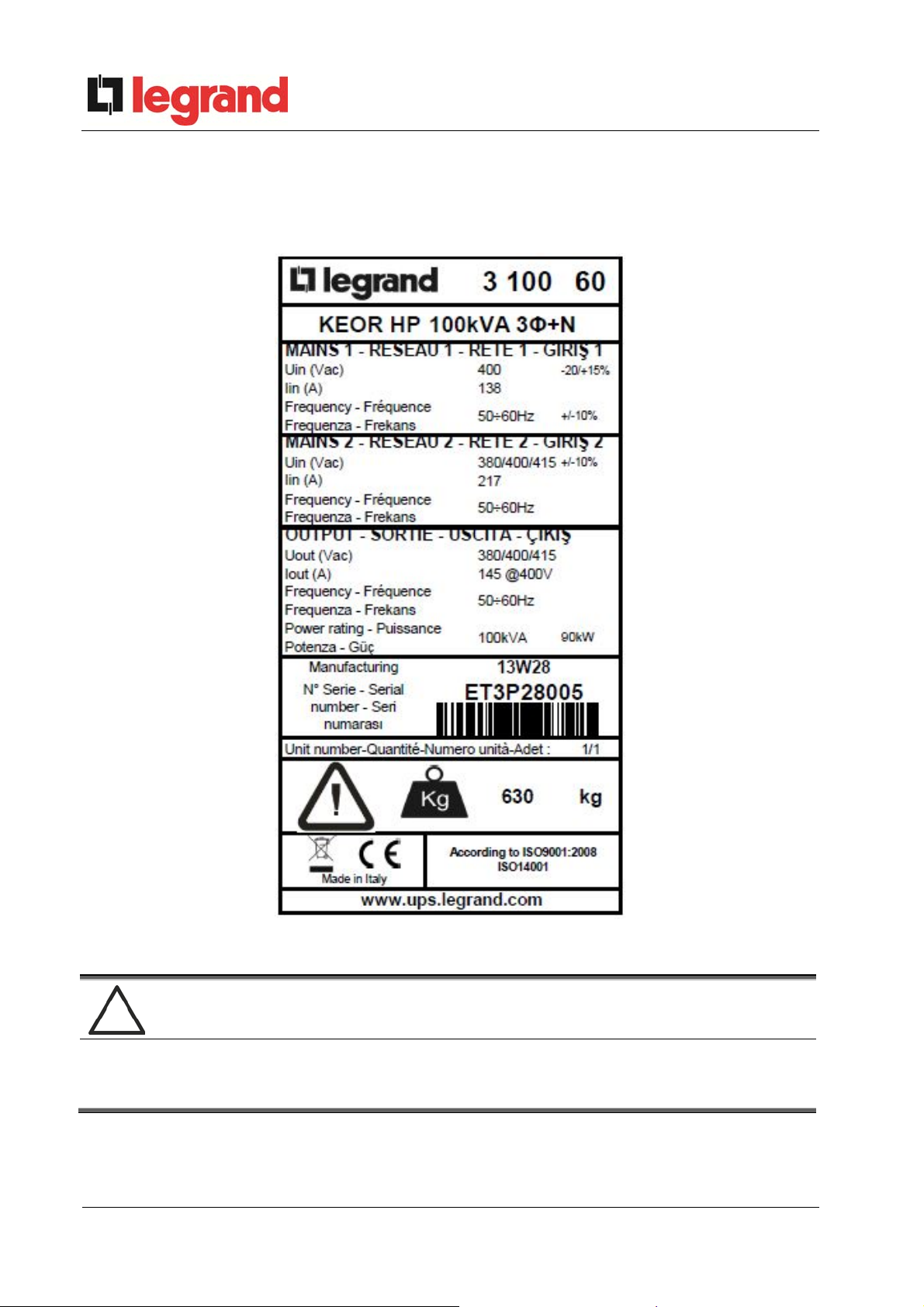
2.2 KEOR HP RATING
UPS KEOR HP is provided with an identification plate containing the operation ratings. The
plate is fixed on the inside of the door.
Picture 1 – Rating plate of KEOR HP
Check the technical characteristics
Before carrying out any installation or start-up operation on the UPS, make sure its
technical characteristics are compatible with the AC supply line and with the output
loads.
10 OMD10073 REV. D
Installation and start-up of UPS Keor Hp 60-160kVA
Installation et démarrage de l'UPS Keor Hp 60-160 kVA
Installazione e avviamento UPS Keor Hp 60-160kVA
2.3 SPECIAL SAFETY WARNINGS
2.3.1 General warnings
UPS KEOR HP is provided with various stickers with indications regarding specific dangers.
These stickers must be always well visible and replaced in case they are damaged.
The present documentation must be always available in proximity to the device. In case of
loss we recommend to request a copy to the manufacturer, whose details are available in the
“Contacts” section.
2.3.2 Personnel
Any operation on UPS KEOR HP must be carried out by qualified personnel.
By qualified and trained person we mean someone skilled in assembling, installing, starting
up and checking the correct operation of the product, who is qualified to perform his/her job and
has entirely read and understood this manual, especially the part regarding safety. Such training
and qualification shall be considered as such, only when certified by the manufacturer.
2.3.3 Transport and handling
Avoid bending or deforming the components and altering the insulation distances while
transporting and handling the product.
Undistributed weight
The weight of the UPS is not uniformly distributed. Pay attention when lifting.
Please inspect the device before installing it. In case any damage is noticed from the
conditions of the package and/or from the outside appearance of the equipment, contact the
shipping company or your dealer immediately. The damage statement must be made within 6
days from receipt of the product and must be notified to the shipping carrier directly. Should the
product need to be returned to the manufacturer, please use the original package.
Injury hazard due to mechanical damage
Mechanical damage to the electrical components constitutes a serious danger to
persons and property. In case of doubt regarding the non-integrity of the package or
of the product contained therein, contact the manufacturer before carrying out the
installation and/or the start-up.
OMD10073 REV. D 11
Installation and start-up of UPS Keor Hp 60-160kVA
Installation et démarrage de l'UPS Keor Hp 60-160 kVA
Installazione e avviamento UPS Keor Hp 60-160kVA
2.3.4 Installation
The product must be installed in strict compliance with the instructions contained in the
technical back-up documentation, including the present safety instructions. In particular, the
following points must be taken into account:
The product must be placed on a base suitable to carry its weight and to ensure its
vertical position;
The UPS must be installed in a room with restricted access, according to standard
CEI EN62040-1;
Never install the equipment near liquids or in an excessively damp environment;
Never let a liquid or foreign body penetrate inside the device;
Never block the ventilation grates;
Never expose the device to direct sunlight or place it near a source of heat.
Special environmental conditions
UPS KEOR HP is designed for normal climatic and environmental operating
conditions as defined in the technical specification: altitude, ambient operating
temperature, relative humidity and environmental transport and storage conditions. It
is necessary to implement specific protective measures in case of unusual
conditions:
harmful smoke, dust, abrasive dust;
humidity, vapour, salt air, bad weather or dripping;
explosive dust and gas mixture;
extreme temperature variations;
bad ventilation;
conductive or radiant heat from other sources;
strong electromagnetic fields;
radioactive levels higher than those of the natural environment;
fungus, insects, vermin.
Use authorized personnel only
All transport, installation and start-up operations must be carried out by qualified and
trained personnel.
The installation of UPS KEOR HP must be carried out by authorized personnel, in
compliance with national and local regulations.
12 OMD10073 REV. D
Installation and start-up of UPS Keor Hp 60-160kVA
Installation et démarrage de l'UPS Keor Hp 60-160 kVA
Installazione e avviamento UPS Keor Hp 60-160kVA
Do not modify the device
Do not modify the device in any way: this may result in damage to the equipment
itself as well as to objects and persons. Maintenance and repair must be carried out
by authorized personnel only. Contact the manufacturer for details of the nearest
service centre.
2.3.5 Electrical connection
The UPS connection to the AC power must be carried out in compliance with the current
regulations.
Make sure the indications specified on the identification plate correspond to the AC power
system and to the actual electrical consumption of all of the equipment connected.
Check the conformity of the documentation
The UPS must be installed according to the requirements of HD 384.4.42 S1/A2 and
in compliance with standard CEI 60346-4-42.
Before connecting the unit to the distribution network, make sure you have received
the approval of the electrical power distribution Authority, so as provided for by the
current national regulations.
IT system
The UPS is also designed to be connected to an IT power distribution system.
All the electrical connections must be carried out by authorized personnel. Before connecting
the device make sure that:
the connection cable to the AC line is properly protected;
the nominal voltages, the frequency and the phase rotation of the AC supply are
respected;
the polarities of the DC cables coming from the battery have been checked;
no leakage current to earth is present.
The device is connected to the following voltage supplies:
DC battery voltage;
AC mains voltage;
AC bypass voltage.
OMD10073 REV. D 13
Installation and start-up of UPS Keor Hp 60-160kVA
Installation et démarrage de l'UPS Keor Hp 60-160 kVA
Installazione e avviamento UPS Keor Hp 60-160kVA
Injury hazard due to electric shock!
The device is subject to high voltages, thus all safety instructions must be
scrupulously adhered to before performing any operation on UPS KEOR HP:
Isolate the battery via DC circuit breakers before connecting it to the UPS;
Connect the ground cable to the relevant bar before carrying out any other
connection inside the device.
Injury hazard due to electric shock!
If primary power isolators are installed in an area other than the UPS one, you must
stick the following warning label on the UPS. “ISOLATE THE UNINTERRUPTIBLE
POWER SUPPLY (UPS) BEFORE WORKING ON THIS CIRCUIT”
2.3.6 Operation
The installations to which the UPS systems belong must comply with all the current safety
standards (technical equipment and accident-prevention regulations). The device can be
started, operated and disconnected only by authorized personnel.
The settings can only be changed using the original interface software.
Injury hazard due to electric shock!
During operation, UPS KEOR HP converts power characterized by high voltages and
currents.
All the doors and the covers must remain closed.
Injury hazard due to contact with toxic substances
The battery supplied with the UPS contains small amounts of toxic materials. To
avoid accidents, the directives listed below must be observed:
Never operate the UPS if the ambient temperature and relative humidity are
higher than the levels specified in the technical documentation.
Never burn the battery (risk of explosion).
Do not attempt to open the battery (the electrolyte is dangerous for the eyes
and skin).
Comply with all applicable regulations for the disposal of the battery.
14 OMD10073 REV. D
Installation and start-up of UPS Keor Hp 60-160kVA
Installation et démarrage de l'UPS Keor Hp 60-160 kVA
Installazione e avviamento UPS Keor Hp 60-160kVA
2.3.7 Maintenance
Service and repairs must be carried out by skilled and authorized personnel. Before carrying
out any maintenance operation, UPS KEOR HP must be disconnected from AC and DC supply
sources.
The device is provided with internal isolators which allow to isolate the internal power circuits.
However the voltages of the supply sources are present on the terminals. To isolate the device
completely, provide external circuit breakers on the lines.
The device contains dangerous voltages even after shutdown and disconnection from the
supply sources, due to the internal capacitors which discharge slowly. Thus we recommend to
wait at least 5 minutes before opening the device doors.
Injury hazard due to electric shock!
Any operation must be carried out only when voltage is absent and in compliance
with safety directives.
Make sure the battery c ircuit breaker that may be placed near the battery has
been opened.
Isolate the device completely by operating the external circuit breakers.
Wait at least 5 minutes in order to allow the capacitors to discharge.
After switching off and disconnecting the device there still might be very hot components
(magnetic parts, heat sinks); therefore we recommend to use protective gloves.
High temperature of components
It is strongly recommended to use protective gloves due to the high temperatures that
may be reached during the operation.
Sectioning of the neutral conductor
The UPS KEOR HP is provided with a sectioning device of the neutral conductor.
The sectioning of the neutral conductor allows the electrical isolation of the UPS
internal parts in order to avoid, during a maintenance or repair, possible operations of
the protective devices on the UPS supply line.
The neutral sectioning device can be opened only when the UPS is in MANUAL
BYPASS operation.
It is mandatory to reconnect the neutral sectiong device before re-starting the UPS.
OMD10073 REV. D 15

Installation and start-up of UPS Keor Hp 60-160kVA
Installation et démarrage de l'UPS Keor Hp 60-160 kVA
Installazione e avviamento UPS Keor Hp 60-160kVA
2.3.8 Storage
If the product is stored prior to installation, it should remain stored in its original package in a
dry place with a temperature ranging from -10°C to +45°C.
Special environmental conditions
It is necessary to implement specific protective measures in case of unusual
environmental conditions:
harmful smoke, dust, abrasive dust;
humidity, vapour, salt air, bad weather or dripping;
explosive dust and gas mixture;
extreme temperature variations;
bad ventilation;
conductive or radiant heat from other sources;
fungus, insects, vermin.
2.4 ENVIRONMENTAL PROTECTION
2.4.1 ISO 14001 certification
Legrand is particularly sensitive to the environmental impact of its products. That is why UPS
KEOR HP has been manufactured with cutting-edge eco-design criteria (ISO 14001
certification).
Special care was taken in using fully recyclable materials and in reducing the amounts of raw
materials used.
2.4.2 Recycling of packing materials
Packing materials must be recycled or disposed of in compliance with applicable local and
national laws and regulations.
2.4.3 Device disposal
At the end of their product life, the materials composing the device must be recycled or
disposed of in compliance with the current local and national laws and regulations.
16 OMD10073 REV. D
Installation and start-up of UPS Keor Hp 60-160kVA
Installation et démarrage de l'UPS Keor Hp 60-160 kVA
Installazione e avviamento UPS Keor Hp 60-160kVA
3 INSTALLATION
3.1 RECEIPT OF THE UPS
Please inspect the device before installing it. In case any damage is noticed from the
conditions of the package and/or from the outside appearance of the equipment, contact the
shipping company or your dealer immediately. The damage statement must be made within 6
days from receipt of the product and must be notified to the shipping carrier directly. Should the
product need to be returned to the manufacturer, please use the original package.
Danger to persons due to transport damages
Mechanical damage to the electrical components constitutes a serious danger to
persons and property. In case of doubt regarding the non-integrity of the package or
of the product contained therein, contact the manufacturer before carrying out the
installation and/or the start-up.
3.1.1 Storage
The package normally ensures protection from humidity and possible damages during
transport. Do not store the UPS outdoor.
Risk of damage due to inappropriate storage
For the environmental storage conditions, refer to the indications given for the
installation of the device.
The device must only be stored in rooms protected from dust and humidity.
The device cannot be stored outdoor.
OMD10073 REV. D 17
Installation and start-up of UPS Keor Hp 60-160kVA
Installation et démarrage de l'UPS Keor Hp 60-160 kVA
Installazione e avviamento UPS Keor Hp 60-160kVA
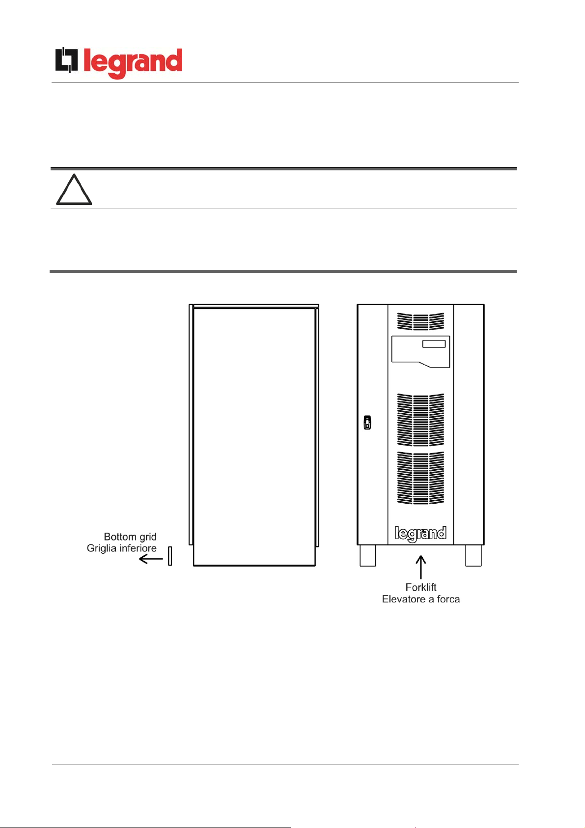
3.2 HANDLING OF THE UPS
The UPS is packed on a pallet. It is handled from the transport vehicle to the installation (or
storage) place via a fork lift.
The device has a heavy weight
To handle the UPS remove the lower front and rear panel and insert the forks of a fork lift.
Avoid turnover during the transport of the UPS.
Cabinets must always be handled in upright position.
During loading and unloading operations, always respect the indications
regarding the device barycentre marked on the package.
Picture 2 – Handling of UPS KEOR HP
18 OMD10073 REV. D

Installation and start-up of UPS Keor Hp 60-160kVA
Installation et démarrage de l'UPS Keor Hp 60-160 kVA
Installazione e avviamento UPS Keor Hp 60-160kVA
3.3 POSITIONING AND INSTALLATION
UPS KEOR HP must be installed indoor, in a clean and dry room, preferably without dust or
humidity infiltrations. For the environmental conditions in the place of installation, in compliance
with the current legislation, please refer to the “Ventilation” section.
Special environmental conditions
It is necessary to implement specific protective measures in case of unusual
environmental conditions:
harmful smoke, dust, abrasive dust;
humidity, vapour, salt air, bad weather or dripping;
explosive dust and gas mixture;
extreme temperature variations;
bad ventilation;
conductive or radiant heat from other sources;
fungus, insects, vermin.
OMD10073 REV. D 19
Installation and start-up of UPS Keor Hp 60-160kVA
Installation et démarrage de l'UPS Keor Hp 60-160 kVA
Installazione e avviamento UPS Keor Hp 60-160kVA
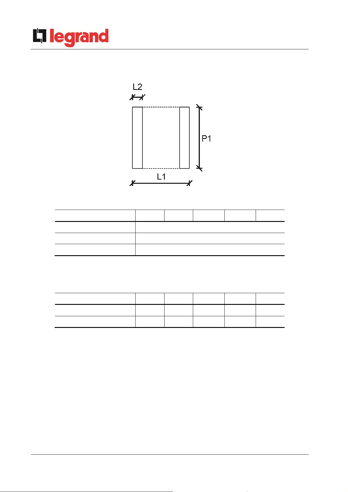
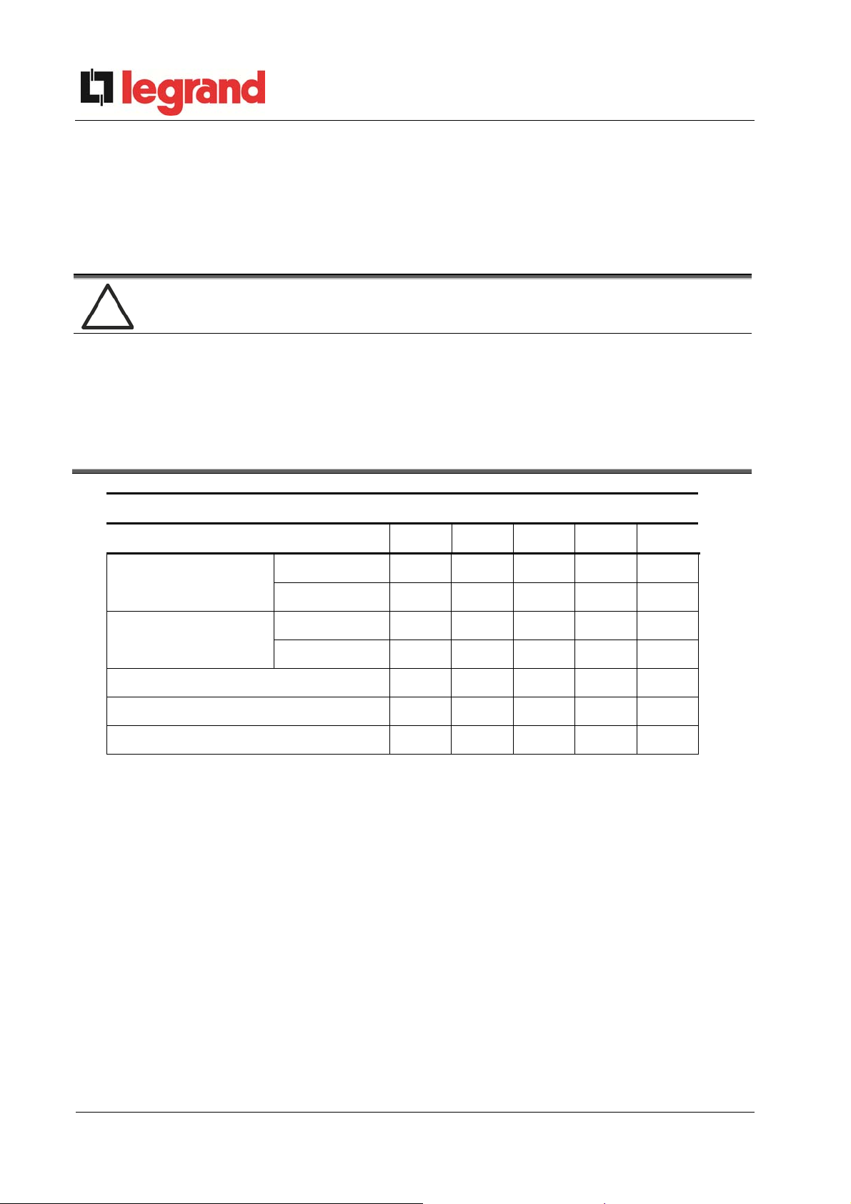
3.3.1 Base plan, static load and weights
Picture 3 – Base plan
Power (kVA) 60 80 100 125 160
L1 (mm) 815
P1 (mm) 825
L2 (mm) 70
The supporting base of the UPS must be designed to carry the UPS weight and to ensure its
steady and safe support.
Its carrying capacity must be adequate to the static loads indicated in the table below.
Power (kVA) 60 80 100 125 160
Weight (kg) 570 600 625 660 715
Static load (kg/m2) 948 998 1040 1098 1190
20 OMD10073 REV. D
Installation and start-up of UPS Keor Hp 60-160kVA
Installation et démarrage de l'UPS Keor Hp 60-160 kVA
Installazione e avviamento UPS Keor Hp 60-160kVA
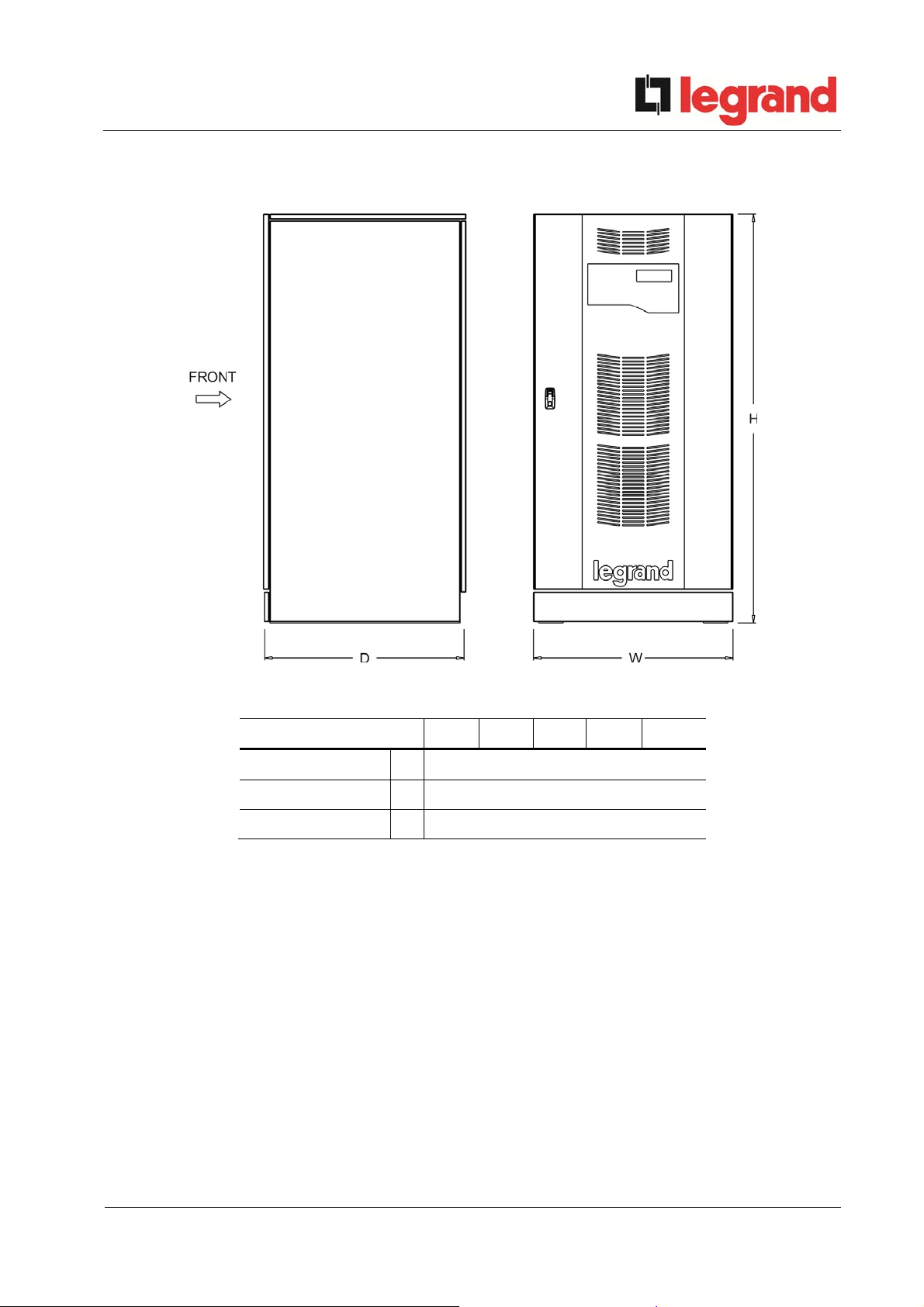
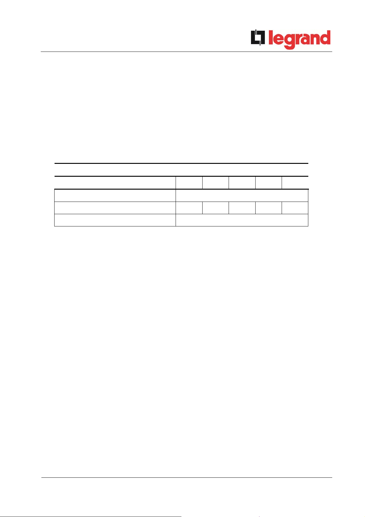
3.3.2 Overall dimensions
Picture 4 – Overall dimensions of UPS KEOR HP
Power (kVA) 60 80 100 125 160
Width (mm)
Depth (mm)
Height (mm)
W
D
H
815
825
1670
OMD10073 REV. D 21
Installation and start-up of UPS Keor Hp 60-160kVA
Installation et démarrage de l'UPS Keor Hp 60-160 kVA
Installazione e avviamento UPS Keor Hp 60-160kVA
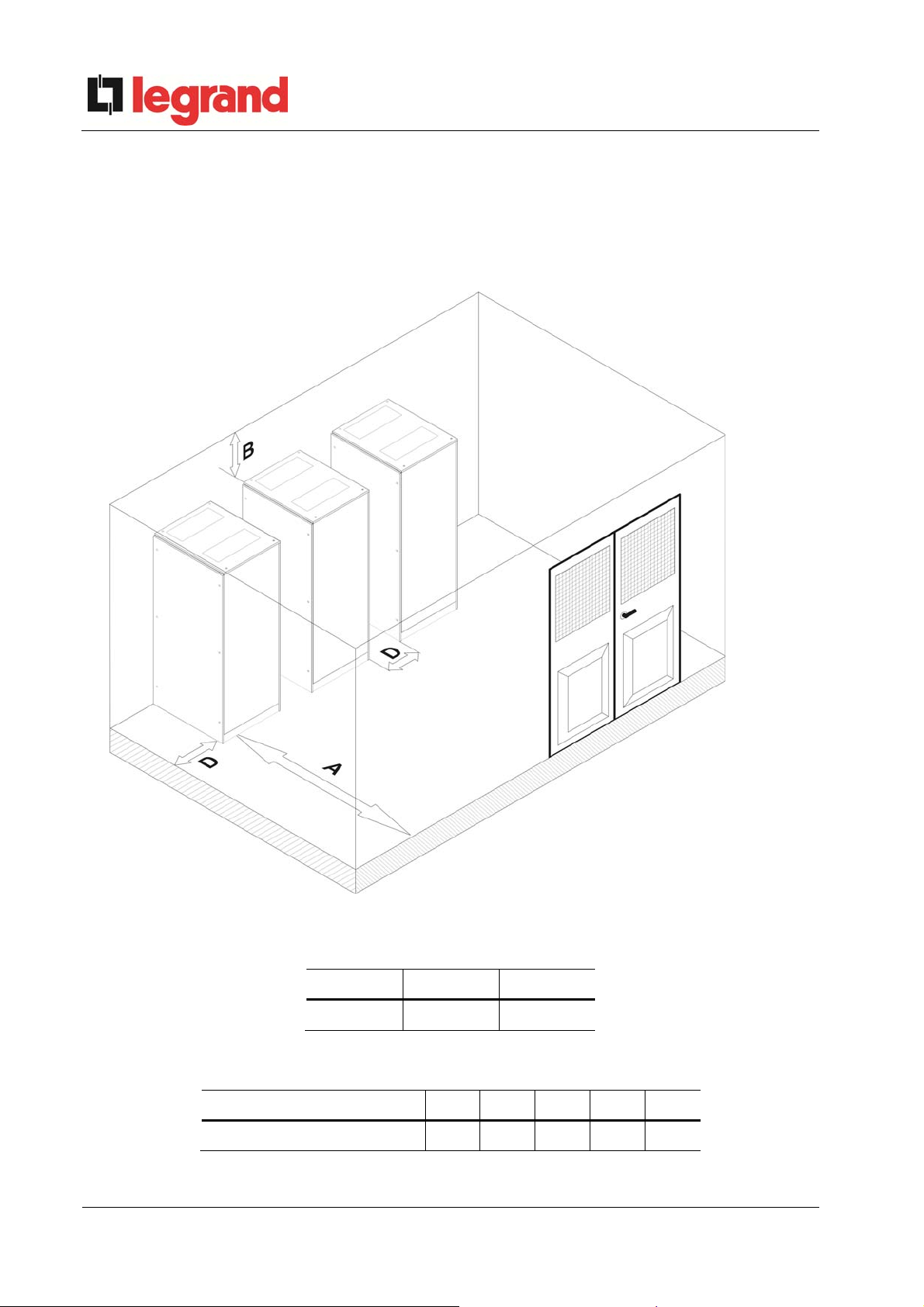
3.3.3 Minimum distances from the walls and ventilation
The UPS must be so installed as to ensure its serviceability and to allow a correct air flow as
much as possible.
With regard to the minimum distances from the walls, for all of the UPS sizes the same
installation conditions apply as indicated in the table below.
Picture 5 – Minimum distances from the walls
A (mm) B (mm) D (mm)
1000 700 50
The table below shows the air volume required for an optimal ventilation and cooling of the
UPS.
Power (kVA) 60 80 100 125 160
Air volume (m3/h) 1600 1800 2100 2300 2500
22 OMD10073 REV. D

Installation and start-up of UPS Keor Hp 60-160kVA
Installation et démarrage de l'UPS Keor Hp 60-160 kVA
Installazione e avviamento UPS Keor Hp 60-160kVA
3.3.4 Environmental installation conditions
The air is classified by the EN 60721-3-3 standard (Classification of environmental
parameters and their severities – Stationary use at weather-protected locations) based on
climatic and biological conditions as well as on mechanically and chemically active substances.
Therefore the place of installation must meet specific requirements to ensure compliance
with the conditions for which the UPS was designed.
Climatic conditions according to the technical specification of KEOR HP
Environmental parameter
Minimum operating temperature (°C) – 10
Maximum operating temperature (°C) + 40
Minimum relative humidity (%) 5
Maximum relative humidity (%) 95
Condensation NO
Rainfall with wind (rain, snow, hail, etc.) NO
Water with an origin other than rain NO
Ice formation NO
Classification of biological conditions (EN 60721-3-3)
Class
Presence of mildew, fungus,
etc.
Presence of rodents and
other animals that are
harmful to products,
including termites
Environmental
parameter
a) Flora
b) Fauna
3B1 3B2 3B3
NO
NO
Presence of mildew, fungus,
etc.
Presence of rodents and
other animals that are
harmful to products,
excluding termites
Classification of mechanically active substances (EN 60721-3-3)
Environmental parameter
Class
3S1 3S2 3S3 3S4
a) Sand [mg/m
b) Dust (suspe nsion) [mg/m
c) Dust (sedimentation) [mg/(m
Places where precautions have been taken to minimize the presence
of dust. Places away from dust sources
Places without any special precaution to minimize the presence of
sand or dust, however not in proximity to sand or dust sources
Places in proximity to sand or dust sources X
Places in proximity to working processes that generate sand or dust,
or in geographic areas having a high proportion of sand brought by
the wind or of dust suspended in the air
3
]
3
]
2
·h)
No 30 300 3000
0,01 0,2 0,4 4,0
0,4 1,5 15 40
X
X
X
OMD10073 REV. D 23

Installation and start-up of UPS Keor Hp 60-160kVA
Installation et démarrage de l'UPS Keor Hp 60-160 kVA
Installazione e avviamento UPS Keor Hp 60-160kVA
Classification of chemically active substances (EN 60721-3-3)
Environmental parameter
a) Sea salt
b) Sulphur dioxide [mg/m
c) Hydrogen sulphide [mg/m
d) Chlorine [mg/m
3
]
e) Hydrochloric acid [mg/m
f) Hydrofluoric acid [mg/m
g) Ammoni a [mg/m
h) Ozone [mg/m
3
3
]
i) Nitric oxide (expressed in equivalent valu es of
nitrogen dioxide) [mg/m
Places where atmosphere is strictly monitored and
regulated (“clean spaces” category)
Places where atmosphere is permanently
monitored
Places located in rural and urban regions where
industrial activities are few and where traffic
is moderate
3
]
3
]
3
]
3
]
]
3
]
Class
3C1R 3C1L 3C1 3C2 3C3 3C4
No No No
0,01 0,1 0,1 1,0 10 40
0,0015 0,01 0,01 0,5 10 70
0,001 0,01 0,1 0,3 1,0 3,0
0,001 0,01 0,1 0,5 5,0 5,0
0,001 0,003 0,003 0,03 2,0 2,0
0,03 0,3 0,3 3,0 35 175
0,004 0,01 0,01 0,1 0,3 2,0
0,01 0,1 0,1 1,0 9,0 20
X
X
X
Salt
fog
Salt
fog
Salt
fog
Places located in urban regions with industrial
activities and/or considerable traffic
Places in proximity to industrial sources with
chemical emissions
Places located in industrial installations.
Emissions of highly concentrated chemical
pollutants
X
X
X
UPS KEOR HP is designed to be installed in an environment that meets the following
classifications.
K Climatic conditions
B Biological conditions
C Chemically active substances
S Mechanically active substances
In accordance with the technical
specification
3B1 (EN 60721-3-3)
3C2 (EN 60721-3-3)
3S2 (EN 60721-3-3)
In the event that the environmental conditions of the installation room do not comply with the
specified requirements, additional precautions must be taken to reduce excessive values to the
specified limits.
24 OMD10073 REV. D
Installation and start-up of UPS Keor Hp 60-160kVA
Installation et démarrage de l'UPS Keor Hp 60-160 kVA
Installazione e avviamento UPS Keor Hp 60-160kVA
4 ELECTRICAL CONNECTION
The electrical connection is part of the work which is normally provided by the company that
carries out the product installation. For this reason, the UPS manufacturer shall not be held
responsible for any damages due to wrong connections.
Use qualified personnel only
All the operations related to the electric connection must be carried out by qualified
and trained personnel.
Work in compliance with the local standards
The installation of UPS KEOR HP must be carried out in compliance with national
and local regulations.
Connection of ground cable
The grounding of the UPS via the relevant terminal is mandatory. It is strongly
recommended to connect the ground terminal as first terminal.
Check the position of selector “SR”
Before using the UPS, make sure changeover switch “SR” (Service switch) is in
“NORMAL” position and keep it in the same position during operation. To use this
changeover switch, refer to the service manual.
The electrical connection is part of the work which is normally provided by the company that
carries out the electrical installation and not by the UPS manufacturer. For this reason, the
following recommendations are only an indication, as the UPS manufacturer is not responsible
for the electrical installation. In any case we recommend to carry out the installation and the
electrical input and output connections in compliance with the local standards.
Cables must be selected bearing in mind technical, financial and safety aspects. The
selection and the sizing of cables from a technical viewpoint depend on the voltage, on the
current absorbed by the UPS, on the bypass line and on the batteries, on the ambient
temperature and on the voltage drop. Finally, the kind of cable laying must be taken into
particular consideration.
For more explanations regarding the selection and the sizing of cables, please refer to the
relevant IEC standards, in particular to IEC 64-8 standard.
“Short-circuit currents” (very high currents with a short duration) and “overload currents”
(relatively high currents with a long duration) are among the main causes of cable damage. The
protection systems normally used to protect the cables are: thermal magnetic circuit breakers or
fuses. Protection circuit breakers must be selected according to the maximum short-circuit
current (max Isc) that is needed to determine the breaking power of automatic circuit breakers,
OMD10073 REV. D 25
Installation and start-up of UPS Keor Hp 60-160kVA
Installation et démarrage de l'UPS Keor Hp 60-160 kVA
Installazione e avviamento UPS Keor Hp 60-160kVA
and to the minimum current (min Isc) that is needed to determine the maximum length of the
line protected. The protection against short-circuit must operate on the line before any thermal
and electrothermal effects of the overcurrents may damage the cable and relevant connections.
During the electrical installation take particular care to respect the phase rotation. The
terminal boards for cables connection are positioned at the front of the UPS, under the
breakers. To access the terminals remove the front protection, extracting the fixing bolts.
Mains connection
The connection to the mains must be carried out with protection fuses between the
mains and the UPS.
The use of differential protection devices in the line supplying the UPS is
unadvisable. The leakage current to ground due to the RFI filters is rather high
and it can cause spurious tripping of the protection device.
According to CEI EN62040-1 standard, in order to take into account the UPS’
leakage current, residual current devices having adjustable threshold can be used.
Power (kVA) 60 80 100 125 160
Input Fuses (A)
Input cables
2
(mm
)
Ground cables (mm
Output cables (mm
Battery cables (mm
Electrical connection data
Rectifier 3x125 3x150 3x200 3x250 3x315
Bypass 3x150 3x200 3x315 3x315 3x400
Rectifier 3x35 3x50 3x70 4x95 3x120
Bypass 4x35 4x50 4x70 4x95 4x120
2
) 16 25 35 50 70
2
) 4x35 4x50 4x70 4x95 4x120
2
) 2x35 4x50 4x70 2x95 2x120
26 OMD10073 REV. D
Installation and start-up of UPS Keor Hp 60-160kVA
Installation et démarrage de l'UPS Keor Hp 60-160 kVA
Installazione e avviamento UPS Keor Hp 60-160kVA
4.1 BACKFEED PROTECTION DEVICE
The back-feed protection device, as indicated by the EN 62040-1 is provide inside the UPS.
The device is a contactor that automatically disconnects the bypass line in case of failure of
the static switch, in order to avoid voltage feed-back on the input terminals during the a mains
failure.
The use of a device installed inside the UPS allows a higher flexibility of use, as only the
bypass line is cut leaving the rectifier battery charger in operation.
The use of an external device forces the user to separate the UPS supply lines (rectifier and
bypass) if the flexibility and availability of the UPS are supposed to be kept unaltered.
The following table shows the main electrical characteristics of the external sectioning device
in case this solution is chosen.
Backfeed protection device
UPS power (kVA) 60 80 100 125 160
Maximum operating voltage (Vac) 690
Minimum rated current (A) 130 180 220 270 350
Category AC-1
OMD10073 REV. D 27
Installation and start-up of UPS Keor Hp 60-160kVA
Installation et démarrage de l'UPS Keor Hp 60-160 kVA
Installazione e avviamento UPS Keor Hp 60-160kVA
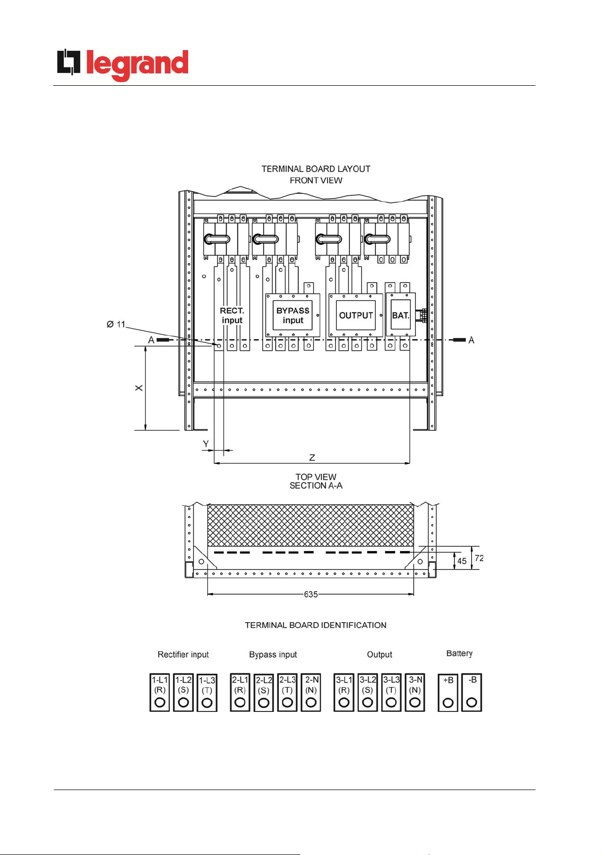
4.2 TERMINAL BOARDS
UPS KEOR HP is provided with terminal boards for the connection of power cables and of
auxiliary connections.
Picture 6 – Position of power terminals of KEOR HP
28 OMD10073 REV. D
Installation and start-up of UPS Keor Hp 60-160kVA
Installation et démarrage de l'UPS Keor Hp 60-160 kVA
Installazione e avviamento UPS Keor Hp 60-160kVA
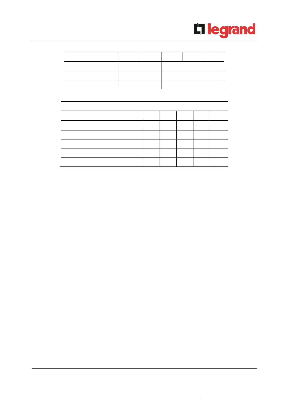
Power (kVA) 60 80 100 125 160
X (mm) 270 260
Y (mm) 18 30
Z (mm) 598 615
Connection data of terminal boards
Power (kVA) 60 80 100 125 160
Terminal board size (mm) 18x5 18x5 30x5 30x5 30x5
Battery terminal board size (mm) 20x5 20x5 30x5 30x5 30x5
Hole diameter (mm) 9 9 11 11 11
Max. cable section (mm2) 95 120 150 185
185
Tightening force (Nm) 15 15 20 25 25
OMD10073 REV. D 29
Installation and start-up of UPS Keor Hp 60-160kVA
Installation et démarrage de l'UPS Keor Hp 60-160 kVA
Installazione e avviamento UPS Keor Hp 60-160kVA
4.3 CONNECTION OF POWER CABLES
For the electric connection of UPS KEOR HP, connect the following cables:
DC supply from the battery;
AC supply from the rectifier and bypass supply mains;
AC output to the loads.
Injury hazard due to electric shock!
Very high voltages are present at the ends of the cables coming from the battery:
Isolate the battery via DC circuit breakers before connecting it to the UPS;
Connect the ground cable to the relevant bar before carrying out any other
connection inside the device.
Risk of damages to the device due to insufficient insulation
The cables must be protected from short-circuits and leakage currents to earth;
The connection points must be hermetically sealed to prevent the air from
being sucked through the cable passage.
Risk of damages to the device due to incorrect wiring
To connect the device, follow the electrical drawing scrupulously and respect the
polarity of cables.
30 OMD10073 REV. D
 Loading...