

Page 1
INSTRUCTION / INSTALLATION SHEET
Outdoor Color IR Camera
301Fulling Mill Road, Suite G
Middletown, PA 17057
Phone (800) 321-2343 / Fax (717) 702-2546
www.onqlegrand.com
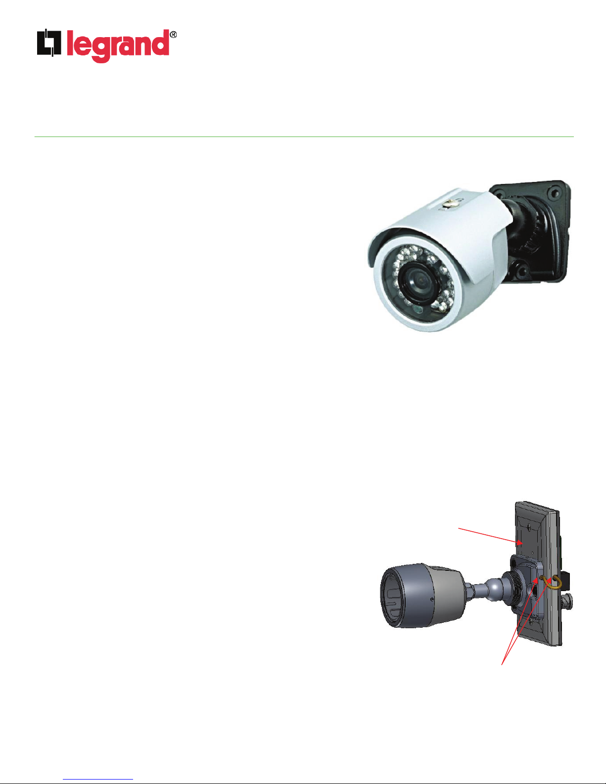
1. INTRODUCTION
The Outdoor Color IR Camera (see Figure 1 ) from Legrand
uses standard Cat 5 wire between the IR Camera and the
Camera Module in the enclosure to deliver crisp video images,
audio, and power. The camera image can be viewed at a
Legrand LCD Console in the home, over the Internet, from a
local TV, or from a smart phone.
2. DESCRIPTION
The Outdoor IR Camera features a 1/3” Color Sony Super HAD
II lens with a 24 piece IR LED. It supports a 510 x 492 resolution
with a minimum illumination of .01 lux with the IR off and 0 lux
with the IR on. The camera is available by itself as P/N CM1027,
or can be mounted onto a custom mounting plate (P/N CM1028),
or is available as a kit with the custom mounting plate as P/N
CM1029. It is even available as a super kit as P/N CM1030,
which also includes the Legrand Camera Module (P/N CM1011).
In order to use the optional microphone (P/N F7642 - not
included), the camera must be mounted onto the custom
mounting plate.
IS-0537 Rev. A
Figure 1
3. INSTALLATION
ROUGH-IN
The rough-in for this product consists of simply running a single Cat 5 cable to a mounted single gang box in the
location of your choice, and crimping an RJ45 modular connector to the ends of the Cat 5 cable.
TRIM-OUT
A. At the single gang box, pull the terminated Cat 5 cable out of
the box.
B. Screw the IR Camera mount assembly to the custom
mounting plate with the three black screws provided, being
careful to run the cable from the camera through the notch in
the mounting arm (see Figure 2).
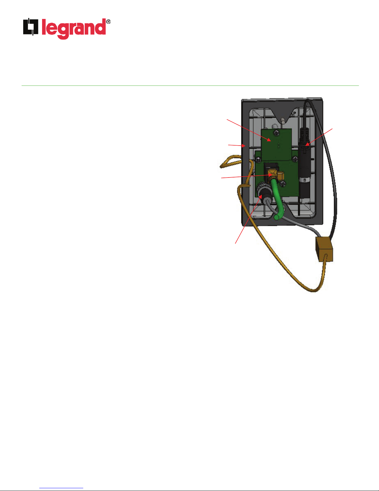
C. A circuit board (see Figure 3) is provided which should be
installed on the rear of the supplied custom mounting plate
with the three screws provided (connectors facing out).
D. The cable from the IR Camera is pre-terminated with two
ends, one is a BNC type connector and the other is a power
connector. Plug the BNC connector into the BNC jack on the
circuit board and the power connector into the power jack on
the circuit board (see Figure 3).
E. If an optional microphone circuit board (see Figure 3) was
ordered, install it by carefully pushing it onto the six pins
protruding from the previously mounted circuit board and
secure it with the provided screw.
Custom
Mounting
Plate
notches
Figure 2
©Copyright 2011 by Legrand All Rights Reserved. Page 1 of 2
Page 2
INSTRUCTION / INSTALLATION SHEET
Outdoor Color IR Camera
301Fulling Mill Road, Suite G
Middletown, PA 17057
Phone (800) 321-2343 / Fax (717) 702-2546
www.onqlegrand.com
F. Carefully route the cable from the camera
through the notch in the custom mounting plate
and bundle the remaining cable together for
storage in the single gang box.
G. Place the supplied gasket (see Figure 3) around
the perimeter of the mounting plate, and plug the
Cat 5 cable into the RJ45 jack on the circuit
board (see Figure 3).
H. Hold the camera assembly against the single
gang box, insuring the gasket is properly seated
around the edge, and secure the assembly to
the box with the two provided screws.
I. In the enclosure, simply plug the other end of
the Cat 5 cable into an available RJ45 jack on
the CM1011 Camera Module.
4. IMPORTANT NOTICE
Use of audio or video equipment for recording the image
or voice of a person without their knowledge and
consent is prohibited in certain states or jurisdictions.
Nothing herein represents a warranty or representation
that the product provided herein is suitable for the enduser's intended use under the applicable laws of his or
her state. Legrand disclaims any liability whatsoever for
any end-user’s use of this product, which fails to comply
with applicable state, local, or federal laws.
IS-0537 Rev. A
Microphone
board
(optional)
gasket
Cat 5
connector
BNC
connector
Figure 3
Power
connector
©Copyright 2011 by Legrand All Rights Reserved. Page 2 of 2
 Loading...