

Page 1
INSTRUCTION / INSTALLATION SHEET
Selective Call Intercom Patio Unit
301Fulling Mill Road, Suite G
Middletown, PA 17057
Phone (800) 321-2343 / Fax (717) 702-2546
www.onqlegrand.com
1. Introduction
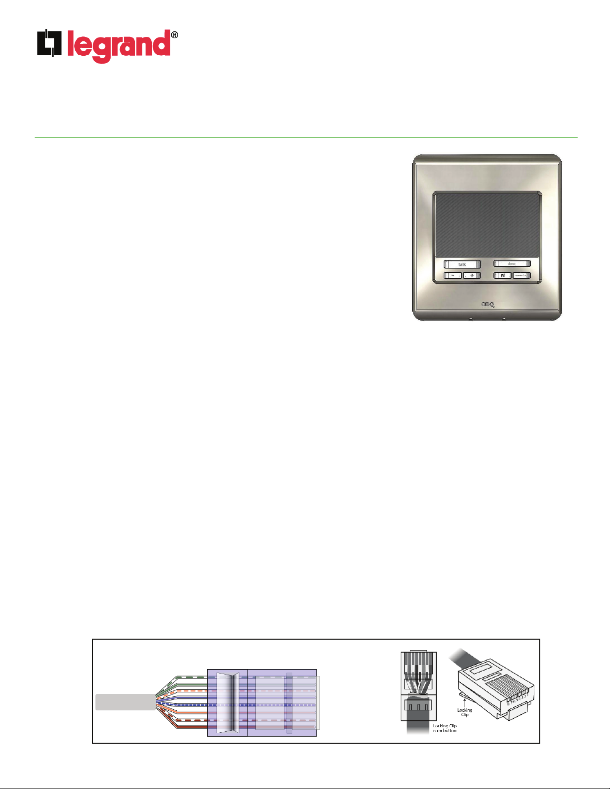
The Legrand Selective Call Intercom Patio Unit, PN IC5004-XX (see
Figure 1), is weather resistant for outdoor use, and supports responding
to a selective call, initiating a page within the house, local control of the
mute and monitor functions and the ability to talk to a Door Unit. A
separate high quality speaker and microphone provide superior sound
quality. It is available in white (-WH), shiny brass (-SB), antique brass (AB), brushed stainless (-BS) and oil-rubbed bronze (-OB).
2. Description
The Patio Unit is a 2-gang product that mounts within an outdoor
weatherproof box (56” from the floor to the bottom of the box). There is
also a two-gang surface-mount box available (P/N IC5006-BK) for unique
or retrofit installation requirements.
3. Installation
Installation of the Selective Call Patio Unit is best accomplished at multiple times during new construction, at
“Rough-in” before the drywall is installed, and at “Trim-out” after the drywall is installed and painted.
A. “Rough-in” steps:
1. Run a Cat 5 cable from the Enclosure where the Selective Call Intercom Module will be installed to the
2 gang box at the Selective Call Patio Unit location.
NOTE: The maximum Cat 5 cable run distance between the SCI Module and another unit (Module,
Door, Patio or Room Unit) is 330’ with the following exception. One Door or Patio Unit may be placed
up to 1000’ (up to 650’ for a Video Door Unit) from the SCI Module, but it needs to be locally powered
and Legrand needs to be informed of and pre-approve this type of installation. If the Cat 5 run is
buried in an underground conduit, it should maintain a 16” separation from any 110VAC wiring.
Additional SCI Modules are recommended to be placed in the same enclosure, powered from the
same power strip, and interconnected with the shortest Cat 5 connections possible.
NOTE: It is important to keep all in-wall Category 5e cable runs at least 12 inches away from AC
electrical cables. If it proves necessary to cross an existing AC cable, do so only at a 90 degree angle.
B. “Trim-out” steps:
NOTE: All terminations can be correctly completed by following the T568A pin assignments. It is
important that you accurately terminate using T568A at all locations. All terminations of the Selective Call
Intercom System are RJ45 jacks. Refer to Figure 2 for correct T568A termination of RJ45 plugs.
Figure 2
IS-0388 Rev. B
Figure 1
Pin
RJ-45
RJ-45
Pin
1 – White/Green
1 – White/Green
2 – Green
2 – Green
3 – White Orange
3 – White Orange
4 – Blue
4 – Blue
5 – White/Blue
5 – White/Blue
6 – Orange
6 – Orange
7 – White/Brown
7 – White/Brown
8 – Brown
8 – Brown
©Copyright 2011 by Legrand All Rights Reserved. Page 1 of 3
Page 2
INSTRUCTION / INSTALLATION SHEET
Selective Call Intercom Patio Unit
301Fulling Mill Road, Suite G
Middletown, PA 17057
Phone (800) 321-2343 / Fax (717) 702-2546
www.onqlegrand.com
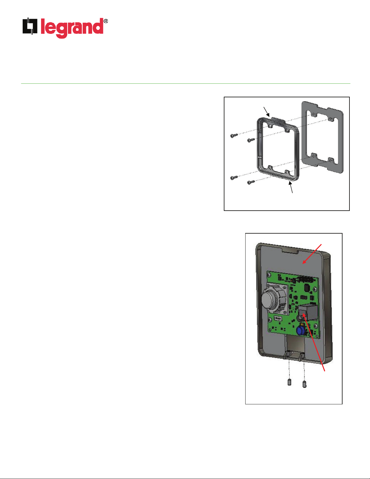
NOTE: Make sure that the included weather proofing gasket is placed as shown in Figure 3.
1. As shown in Figure 3, the first step to installing the
Selective Call Patio Unit is to place the included rear
gasket against the gang or back box, and secure the
gasket in place with the included mounting bracket.
NOTE: Insure that the mounting bracket is installed with
the center tab pointed up, as the Patio Unit will be
“hung” from this tab in a later step.
NOTE: There are slotted holes in the mounting bracket
to allow for leveling of the Patio Unit in case the gang or
back box was installed off level.
2. Use the four provided screws to attach the mounting
bracket to the gang or back box.
3. Pull the Cat 5 cable from the enclosure through the
mounting bracket and terminate the cable with an RJ45
plug and insert the plug into the RJ45 jack on the rear of
the Patio Unit (see Figure 4). Follow the T568A
standards described in Figure 2.
4. Hang the Patio Unit from the top tab on the mounting bracket
and use the provided 1/16” allen wrench to tighten the two set
screws at the bottom of the Patio Unit.
5. Terminate the other end of the Cat 5 cable, at the Selective Call
Intercom Module, with an RJ45 plug using the T568A wiring
standard.
6. Insert the RJ45 plug into any of the eight Room, Patio, or Door
Unit jacks on the Intercom Module, (labeled 1-8).
7. After all Units and Modules are connected, apply power to the
Selective Call Intercom Module and verify system functionality.
All Selective Call Room, Door and Patio Units will be discovered
and shown on each Room Unit LCD.
4. Operation
IS-0388 Rev. B
center tab
rear
gasket
mounting
bracket
Figure 3
front gasket
RJ45
jack
set screws
Figure 4
©Copyright 2011 by Legrand All Rights Reserved. Page 2 of 3
Page 3

INSTRUCTION / INSTALLATION SHEET
Selective Call Intercom Patio Unit
301Fulling Mill Road, Suite G
Middletown, PA 17057
Phone (800) 321-2343 / Fax (717) 702-2546
www.onqlegrand.com
Please refer to Figure 5 to familiarize yourself with the basic operation of the Selective Call Intercom Patio Unit.
Please refer to the Selective Call System Installation Manual (P/N 1308003) shipped with the SCI Module for
more detailed instructions on how to use any Selective Call Room Unit to configure and personalize the
Selective Call System.
By default, the Patio Unit will not respond to Page All commands or hear internally monitored rooms. These
settings can be changed to allow both actions by using any Room Unit to change the defaults.
talk: Depressing this button will allow you to
communicate with all other active units. Hold in the talk
button while speaking, and let it go when you are done.
Your voice will be heard on any active Room or other
enabled Patio Unit within the system. Patio Units cannot
initiate a selective call.
IS-0388 Rev. B
SPEAKER
MICROPHONE
door: Depressing this button will allow you to communicate
with the last Door Unit that rang its door tone. Hold in the
door button while speaking and let it go when you are done.
Figure 5
volume: There are two volume control buttons
labeled + and -. Pressing the volume + button will
increase the volume level. You can also hold in the
volume + or - button until you have reached the
desired volume level.
monitor: Press this button once to put the Unit in
MONITOR mode and the monitor button will change its
normal white backlit color to red. This means that all other
non-Muted and non-Monitored units (other than Doors) will
be able to monitor this unit. If someone wants to contact the
monitored Patio unit they must place a selective call to that
unit. If the Mute button is also pressed, the unit cannot be
contacted. Press the monitor button again to return the Unit
back to normal mode. While in MONITOR mode, the
microphone is constantly active, and any voice or noise
within the area will be heard by any monitoring station. Door
Units are excluded from being Monitoring Stations. Multiple
Units can be in MONITOR mode at the same time.
NOTE: When in MONITOR mode, a door bell button
push at a Door Unit will not result in a door chime ring
at the Patio Unit.
mute: Press this button once to put the Unit in MUTE mode
and the button will change its normal white backlit color to
red. Press the button again to return the Unit back to normal
mode. While in MUTE mode, both the speaker and
microphone of the unit will be inactive. MUTE mode is useful
for maintaining privacy in a particular living space.
©Copyright 2011 by Legrand All Rights Reserved. Page 3 of 3
 Loading...