

Page 1
INSTRUCTION / INSTALLATION SHEET
Selective Call Intercom Distribution
301Fulling Mill Road, Suite G
Middletown, PA 17057
Phone (800) 321-2343 / Fax (717) 702-2546
www.onqlegrand.com
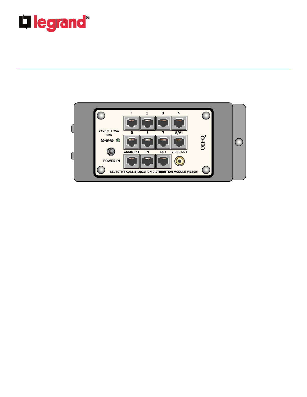
1. Introduction
The Legrand Selective Call Intercom Distribution Module (P/N IC5001) is a single bay module that supports
the audio, power and control requirements of up to 8 units in any combination of Room, Door and Patio (see
Figure 1).
Figure 1
2. Description
The Selective Call Intercom Distribution Module is located in the enclosure and connected to each Room,
Door and Patio Unit via a single Cat 5 cable. Up to eight units of any combination are supported by each
module and modules may be cascaded three times, for a total system support of up to 32 Units. The RJ45
jacks labeled “1-8” are used for the various Units, with jack 8/V1 supporting Video Door Units. The jacks
labeled “IN” and “OUT” are used for cascading modules. The jack labeled “AUDIO INT” is used to connect to
the lyriQ™ Audio Distribution System to automatically mute the whole house audio when the Intercom system
is utilized. The “VIDEO OUT” RCA jack is used to output images from a Video Door Unit. The Module comes
with a single bay bracket for mounting in an On-Q style enclosure.
NOTE: The maximum Cat 5 cable run distance between the SCI Module and another unit (Module,
Door, Patio or Room Unit) is 330’ with the following exception. One Door or Patio Unit may be placed
up to 1000’ (up to 650’ for a Video Door Unit) from the SCI Module, but it needs to be locally powered
and Legrand needs to be informed of and pre-approve this type of installation. If the Cat 5 run is
buried in an underground conduit, it should maintain a 16” separation from any 110VAC wiring.
Additional SCI Modules are recommended to be placed in the same enclosure, powered from the
same power strip, and interconnected with the shortest Cat 5 connections possible.
3. Installation
Installation of the Selective Call Intercom Distribution Module is best accomplished at multiple times during
new construction, at “Rough-in” before the drywall is installed, and at “Trim-out” after the drywall is installed
and painted.
A. “Rough-in” steps:
1. Run a single Cat 5e cable from the Enclosure where the Selective Call Intercom Distribution Module will
be installed to each of the 2 gang boxes at the eventual Room, Door and Patio Unit locations.
Module
IS-0385 Rev. B
©Copyright 2011 by Legrand All Rights Reserved. Page 1 of 4
Page 2
INSTRUCTION / INSTALLATION SHEET
Selective Call Intercom Distribution
301Fulling Mill Road, Suite G
Middletown, PA 17057
Phone (800) 321-2343 / Fax (717) 702-2546
www.onqlegrand.com
NOTE: It is important to keep all Category 5e cable runs, regardless of use, at least 12 inches away
from AC electrical cables. If it proves necessary to cross an existing AC cable, do so only at a 90
degree angle.
B. “Trim-out” steps:
NOTE: All components in the Selective Call Intercom System use RJ45 plugs terminated to the T568A
wiring standard. Refer to Figure 2 for correct T568A termination for RJ45 plugs.
Figure 2
Figure 2
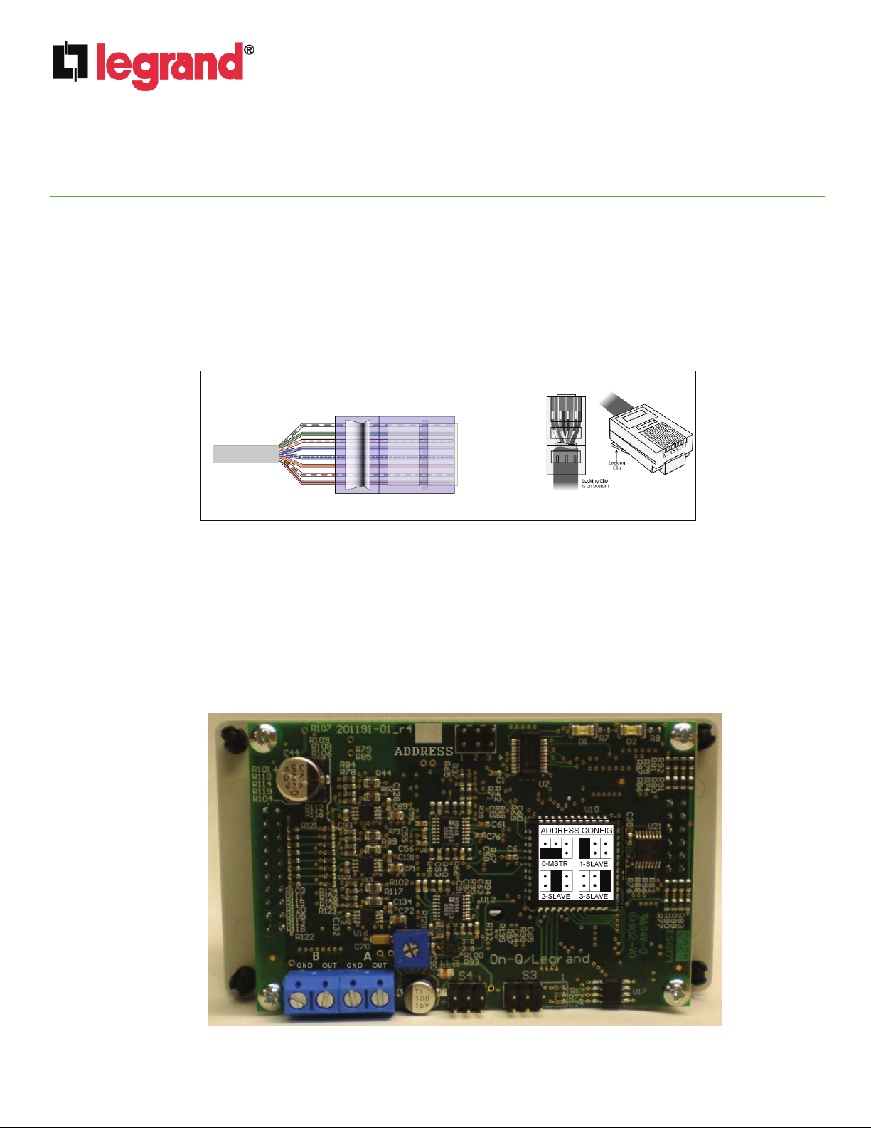
1. As shown in Figure 3, there is an “ADDRESS” jumper block located at the top of the rear of the Selective
Call Intercom Module. This jumper block is used to select the Master module, and up to three Slave
modules when cascading Modules. Each Selective Call Module is shipped with the jumper in the Master
position. Use the diagram to correctly position the jumper for multi-module systems.
2. As also shown in Figure 3, there is also a four position terminal block located on the lower left corner
of the rear of the Selective Call Intercom Module. These are Open Collector Outputs labeled “A” and
“B” (ground and output connectors for each). At any Room Unit, you can configure the “A” Door Strike
(“Release”) and/or “B” Alert (“Trigger”) outputs to be enabled or disabled. See Figure 4 and Figure 5
for an examples of the wiring associated with this terminal block.
Figure 3
Module
RJ-45
RJ-45
Pin
Pin
1 – White/Green
1 – White/Green
2 – Green
2 – Green
3 – White Orange
3 – White Orange
4 – Blue
4 – Blue
5 – White/Blue
5 – White/Blue
6 – Orange
6 – Orange
7 – White/Brown
7 – White/Brown
8 – Brown
8 – Brown
IS-0385 Rev. B
©Copyright 2011 by Legrand All Rights Reserved. Page 2 of 4
Page 3

INSTRUCTION / INSTALLATION SHEET
Selective Call Intercom Distribution
301Fulling Mill Road, Suite G
Middletown, PA 17057
Phone (800) 321-2343 / Fax (717) 702-2546
www.onqlegrand.com
Figure 4
Door
Strike
Wiring
To LCD Module
To LCD Module
to wake up LCD Display
to wake up LCD Display
and show front door
and show front door
camera when door bell
camera when door bell
is pushed
is pushed
Figure 5
Video
Door
Wiring
3. Terminate the other end of the labeled Cat 5e cables, at the Selective Call Intercom Distribution
Module, with RJ45 plugs using the T568A wiring standard and plug them into the appropriate RJ45
jack.
4. After all Units and Modules are connected, apply power to the Intercom Distribution Module and verify
system functionality.
Module
Power
Power
Supply
Supply
A
A
B
B
GND GNDOUT OUT
GND GNDOUT OUT
A
A
B
B
GND GNDOUT OUT
GND GNDOUT OUT
Wake ups LCD Display and
Wake ups LCD Display and
shows front door camera
shows front door camera
when door bell is pushed
when door bell is pushed
GND
GND
TRG
TRG
VID_1
VID_1
Door
Door
Strike
Strike
Relay
Relay
SCI
SCI
Module
Module
(rear view)
(rear view)
SCI
SCI
Module
Module
(rear view)
(rear view)
LCD
LCD
Module
Module
(rear view)
(rear view)
Door
Door
Strike
Strike
IS-0385 Rev. B
©Copyright 2011 by Legrand All Rights Reserved. Page 3 of 4
Page 4

INSTRUCTION / INSTALLATION SHEET
Selective Call Intercom Distribution
301Fulling Mill Road, Suite G
Middletown, PA 17057
Phone (800) 321-2343 / Fax (717) 702-2546
www.onqlegrand.com
4. Operation
Figures 6 and 7 illustrate the use of the Selective Call Module in a 6 location and a 12 location home system.
Note that Figure 7 demonstrates the cascading of modules to increase the number of locations supported.
Figure 8 shows the Video Door Unit used with our LCD Display to see who is at the front door. Please refer to
the Selective Call System User’s Guide (P/N 1308001) shipped with the Room Unit for more detailed
instructions on how to use any Selective Call Room Unit to configure and personalize the Selective Call
System. Refer to the Selective Call System Installation Guide (P/N 1308003) shipped with the Selective Call
Distribution Module to familiarize yourself with the installation of the Selective Call Intercom System.
Figure 6
Figure 8
Module
IS-0385 Rev. B
Figure 7
©Copyright 2011 by Legrand All Rights Reserved. Page 4 of 4
 Loading...