

Page 1

INSTRUCTION / INSTALLATION SHEET
Selective Call Intercom Room Unit
301Fulling Mill Road, Suite G
Middletown, PA 17057
Phone (800) 321-2343 / Fax (717) 702-2546
www.onqlegrand.com
1. Introduction
The Legrand Selective Call Intercom Room Unit, PN IC5000-XX
(see Figure 1), is a critical component of the On-Q Selective
Call Intercom System. Using the intuitive Graphical User
Interface (GUI) provided via the color Liquid Crystal Display
(LCD), it provides both basic intercom communications
functions such as talk, talk to door, monitor, mute, and
advanced functions such as dynamic sorting of users or
monitoring multiple rooms at the same time. The Room Unit
GUI provides the only means to custom configure, or
personalize, the On-Q SCI Intercom System. The Room Unit is
available in white (-WH), light almond (-LA), gloss black (-GB)
and titanium (-TI).
2. Description
The Selective Call Room Unit is a two-gang decorator-style
product that connects to the Selective Call Distribution Module in
the enclosure via a single Cat 5e cable, up to 330’ in length.
3. Installation
Installation of the Selective Call Room Unit is best accomplished
at multiple times during new construction, at “Rough-in” before
the drywall is installed, and at “Trim-out” after the drywall is
installed and painted.
A. “Rough-in” steps:
To provide optimal display quality of the LCD on the Room
Unit, the two gang box that it is mounted in should be
located for eye level operation (see Figure 2). The bottom
of the two gang box should be approximately 56” from the
floor.
1. Run a Cat 5 cable from the Enclosure where the
Selective Call Intercom Distribution Module will be
installed to the 2 gang deep electrical box at the Room
Unit location.
NOTE: It is important to keep all Category 5e cable
runs, regardless of use, at least 12 inches away from
AC electrical cables. If it proves necessary to cross an
existing AC cable, do so only at a 90 degree angle.
IS-0386 Rev. B
Figure 1
Figure 2
©Copyright 2011 by Legrand All Rights Reserved. Page 1 of 3
Page 2
INSTRUCTION / INSTALLATION SHEET
Selective Call Intercom Room Unit
301Fulling Mill Road, Suite G
Middletown, PA 17057
Phone (800) 321-2343 / Fax (717) 702-2546
www.onqlegrand.com
B. “Trim-out” steps:
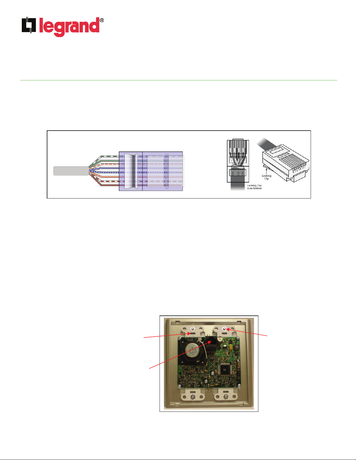
NOTE: All terminations can be correctly completed by following the T568A pin assignments. It is
important that you accurately terminate using T568A at all locations. The Selective Call Intercom
System uses RJ45 plugs for all terminations on the Modules, the Room Units, the Door Units and
Patio Units. Refer to Figure 3 for correct T568A termination for RJ45 plugs.
Figure 3
1. As shown in Figure 4, label and terminate an RJ45 plug on the Cat 5 cable from the Selective Call
Intercom Module and attach it to the RJ45 jack on the rear of the Room Unit. Follow the T568A standards
described in Figure 3.
2. Insert the Selective Call Room Unit in position and the Cat 5 cable into the 2 gang box and secure the
unit to the box using the 4 included panhead screws. If using the included screwless wallplate option,
install mounting plate to Room Unit using 4 flathead screws and snap on the wall plate cover.
3. Terminate the other end of the Cat 5 cable, at the Selective Call Intercom Module, with an RJ45 plug
using the T568A wiring standard.
4. Insert the RJ45 plug into any of the eight ROOM UNIT jacks on the Selective Call Intercom Module in
the enclosure.
IS-0386 Rev. B
Pin
RJ-45
RJ-45
Pin
1 – White/Green
1 – White/Green
2 – Green
2 – Green
3 – White Orange
3 – White Orange
4 – Blue
4 – Blue
5 – White/Blue
5 – White/Blue
6 – Orange
6 – Orange
7 – White/Brown
7 – White/Brown
8 – Brown
8 – Brown
5. After all Units and Modules are connected, apply power to the Selective Call Intercom Module and
verify system functionality. All Selective Call Room, Door and Patio Units will be discovered and
shown on each Room Unit LCD.
Mounting Box screw
location (4 places)
Wall Plate Mounting
Plate screw location
(4 places)
RJ45 jack
Figure 4
©Copyright 2011 by Legrand All Rights Reserved. Page 2 of 3
Page 3

INSTRUCTION / INSTALLATION SHEET
y
Selective Call Intercom Room Unit
301Fulling Mill Road, Suite G
Middletown, PA 17057
Phone (800) 321-2343 / Fax (717) 702-2546
www.onqlegrand.com
4. Operation
Please refer to the Selective Call System Installation Manual (P/N 1308003) shipped with the SCI Module for
more detailed instructions on how to use any Selective Call Room Unit to configure and personalize the
Selective Call System.
LCD: This is the Liquid Crystal Display that is used to
customize, personalize and operate the Selective Call
Intercom System. It identifies which unit is calling you, and
gives you status of all the individual units. It also provides
pop-up messages to inform you of specific operational
parameters.
Figure 5
IS-0386 Rev. B
SPEAKER
MICROPHONE
volume: There are two volume control buttons, labeled +
and -. When either button is pressed, the LCD display turns
into a horizontal volume bar graph. Pressing the volume up
button increases the volume (the bar graph moves to the
right). You can also hold in the volume up or down button
until you have reached the desired volume level. The LCD
changes back to its normal display after 2 seconds of
inactivit
monitor: Press this button once to put the Unit in
MONITOR mode. The LCD will display a message stating
that “MONITOR is On” and the monitor button will change
its normal white backlit color to red. This means that all
other non-Monitored units will be able to listen to this unit.
While in MONITOR mode, the microphone is constantly
active, and any voice or noise within the room will be heard
by any monitoring station. Multiple Units can be in
MONITOR mode at the same time. If someone wants to
contact the monitored unit they must place a selective call
to that unit. Press the monitor button again to return the
Unit back to normal mode. The LCD will tell you “MONITOR
is Off”. If the mute button is also pressed, the LCD will
indicate that you are in MONITOR and MUTE mode and the
unit cannot be contacted.
NOTE: When in MONITOR mode, a door bell button
push at a Door Unit will not result in a door chime ring
at the Room Unit.
mute: Press this button once to put the Unit in MUTE
mode. The LCD will display a message that you are in
talk/select: Depressing this button will allow you to
communicate with any active units selected on the LCD
Display. Hold in the talk/select button while speaking, and
let it go when you are done. Your voice will be heard on
the selected Unit, or any active Room or Patio Unit if All is
selected.
©Copyright 2011 by Legrand All Rights Reserved. Page 3 of 3
MUTE mode and the button will change its normal white
backlit color to red. Press the button again to return the Unit
back to normal mode. The LCD will display a message that
MUTE is Off. While in MUTE mode, both the speaker and
microphone of the unit will be inactive. MUTE mode is useful
for maintaining privacy in a particular room.
 Loading...