

Page 1
WIRING DIRECTIONS
C
ontrol Output 24VDC
C
ommon
+
24VDC
L
ighting
L
oad
W
hite / Neutral
R
ed (Load)
R
ed (Line)
W
hite
B
lackHot
Neutral
P
ower Pack
Red
Black
Blue
Switch
Blue
Red
Black
Blue (Control Output 24VDC)
Red (+24VDC)
White (Neutral)
Red (Load)
Red (Line)
White
BlackHot
N
POWER PACK
Red
Black
Blue
Switch
Black (Control Return)
Blue (Control Output 24VDC)
Red (+24VDC)
Lighting
Load
Lighting
Load
White (Neutral)
Red (Load)
R
ed (Line)
White
Black
H
ot
N
POWER PACK
Red
Black
Blue
Switch
Black (Control Return)
Lens-plane
10ft
0
8ft
8ft
16ft
16ft
0
10 15ft 55ft 85 90ft
33ft
0ft
7ft
10ft
3
15ft 25ft 50ft
0
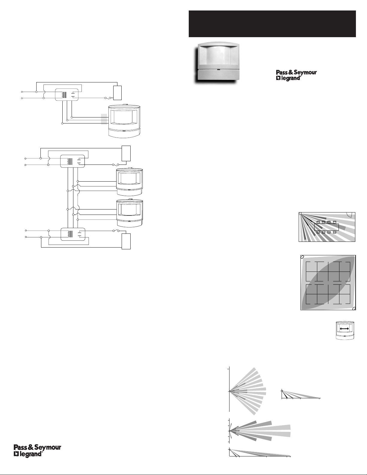
WARNING – Turn power off at the circuit breaker before installing power pack
or sensors.
Note: Each power pack can supply power for up to eight sensors. If using
more than eight sensors, multiple power packs are required.
For normal installation, connect:
BLUE wire from power pack to BLUE wire from sensor.
RED wire from power pack to RED wire from sensor.
and BLACK wire from power pack to BLACK wire from sensor.
ingle Sensor Wiring
S
Multiple Sensors Wiring
LIMITED FIVE YEAR WARRANTY
Pass & Seymour will remedy any defect in workmanship or material in Pass &
Seymour products which may develop under proper and normal use within
five (5) years from date of purchase by a consumer:
(1) by repair or replacement, or, at Pass & Seymour’s option, (2) by
return of an amount equal to consumer’s purchase price. Such remedy is
IN LIEU OF ANY AND ALL EXPRESSED OR IMPLIED WARRANTIES OF
MERCHANTABILITY OR FITNESS FOR A PARTICULAR PURPOSE. Such
remedy by Pass & Seymour does not include or cover cost of labor for
removal or reinstallation of the product. ALL OTHER FURTHER ELEMENTS
OF DAMAGE (INCIDENTAL OR CONSEQUENTIAL DAMAGES) FOR BREACH
OF ANY AND ALL EXPRESSED OR IMPLIED WARRANTIES INCLUDING
WARRANTIES OF MERCHANTABILITY OR FITNESS FOR A PARTICULAR
PURPOSE ARE EXCLUDED HEREBY. (Some states do not allow disclaimer or
exclusion or limitation of incidental or consequential damages, so the above
disclaimers and limitation or exclusion may not apply to you.) ANY IMPLIED
WARRANTIES INCLUDING WHERE REQUIRED WARRANTIES OF
MERCHANTABILITY OR FITNESS FOR A PARTICULAR PURPOSE SHALL BE
LIMITED TO THE FIVE YEAR PERIOD SET FORTH ABOVE. (Some states do
not allow limitations on how long an implied warranty lasts, so the above
limitation may not apply to you.)
To insure safety, all repair to Pass & Seymour products must be made by
Pass & Seymour, or under its specific direction. Procedure to obtain
performance of any warranty obligation is as follows: (1) Contact Pass &
Seymour, Syracuse, New York 13221, for instructions concerning return or
repair, (2) return the product to Pass & Seymour, postage paid, with your
name and address and a written description of the installation or use of the
Pass & Seymour product, and the observed defects or failure to operate, or
other claimed basis for dissatisfaction.
This warranty gives you specific legal rights and you may also have other
rights which vary from state to state.
P.O. Box 4822
Syracuse, NY 13221
(800) 223-4185
Part No. 340400 Rev. D
Printed in U.S.A.
INSTALLATION & OPERATING INSTRUCTIONS
WA1001/HS1001
IR OCCUPANCY SENSOR
P
S Patent No.:
U
,787,722
4
UNIT DESCRIPTION
The WA1001/HS1001 are 24VDC passive infrared (PIR) occupancy sensors
which control lighting or HVAC systems based on occupancy.
PIR sensing systems are passive systems which react to changes in infrared
energy (moving body heat) within the coverage area. PIR sensors must
directly “see” motion of an occupant to detect them, so careful consideration
must be given to sensor placement.
SPECIFICATIONS
Voltage . . . . . . . . . . . . . . . . . . . . . . . . . . . . . . . . . . 24VDC
Power Supply . . . . . . . . . . . Pass & Seymour Power Pack
Current Consumption . . . . . . . . . . . . . . . . . . . 8mA Typical
Time Adjustment . . . . . . . . . . . . . 15 seconds–30 minutes
Sensitivity Adjustment . . . . . . . . . . . . Minimum–Maximum
APPLICATION
Coverage may be slightly less than the maximum sensing distance depending
upon obstacles such as furniture or partitions. This must be considered
when planning the number of sensors and their placement. Also, total
coverage area will be smaller for lower mounting heights.
Enclosed office applications
The best location to install the WA1001 is in a
corner which does not face a door. Avoid placing
the sensor so that it can see out an open door
where it may be able to sense people walking by.
Also, avoid placing the sensor where obstacles
will block its view—the sensor must “see” the
occupants in order to detect them.
Conference Rooms, Large
Office Areas, and Classrooms
For these applications, the WA1001 is best. Place
sensor in the corner facing into the room. To
obtain maximum coverage in a partitioned work
area, use the sensors to create coverage zones
that overlap each other. As a general rule, you
should be able to view the sensor clearly from
each desk in the coverage area.
Aisleways, Hallways and Shelving Areas
In these types of applications, the HS1001 is used.
The HS1001 lens has a narrow, long-range view and should be
installed on a wall or ceiling at the end of an aisleway. It works
best when mounted at 10 ft.
COVERAGE PATTERNS
Coverages shown are maximum and represent coverage for half-step,
walking motion.
TOP
TOP
SIDE
Dense Wide Angle Lens (WA1001)
up to 1200 sq ft
SIDE
Long Range Lens (HS1001)
up to 90 linear ft
Page 2
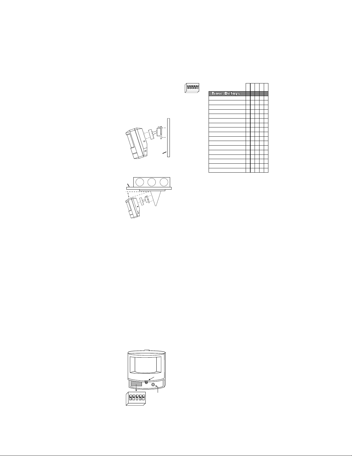
SELECTING SENSOR LOCATION
0°
9
1
8
2
7
J
unction Box
=18°
Sensitivity
Adjustment
Time-Delay
DIP Switch
on
25431
LED
DIP Switch #
15 seconds
4
minutes
6 minutes
8
minutes
1
0 minutes
12 minutes
1
4 minutes
2
minutes
16 minutes
20 minutes
22 minutes
2
4 minutes
2
6 minutes
28 minutes
30 minutes
O
verride
1
8 minutes
1
2345
X
=on O=off
X
X
X
X
X
X
X
X
X
X
XXX
X
X
X
X
X
X
O
O
O
O
XX
X
X
X
X
X
X
X
O
O
O
OOO
O
OOO
O
O
O
X
X
X
O
O
O
O
O
O
O
O
O
O
O
O
O
O
O
O
O
O
O
OOO
O
O
O
O
O
X
X
O
O
O
O
O
O
O
O
Time-Delay
DIP Switch
on
25431
2
7
9
1
8
°
0
Proper placement of the sensor is critical in achieving maximum performance
of the device. Passive infrared sensors respond to movement of heat
sources, such as humans, through their direct viewing area. Use the following
rules when selecting the location of the sensors:
• Do not place sensors where viewing area contains direct air currents, or
concentrated, direct reflected light.
• Sensor viewing is line-of-sight, therefore, do not place sensors where
desired coverage is obstructed by walls, columns or other objects.
• Do not place sensors directly above baseboard heaters or forced air
outlets.
• Use sensors only with lighting loads.
• Sensors should be used in dry, indoor locations.
INSTALLATION
The WA1001 and HS1001 can be mounted to a wall or ceiling. Brackets
are available that give flexibility for positioning the sensor.
Swivel Mount Bracket
The swivel mounting bracket gives the angle
Swivel Mount Bracket
adjustment flexibility needed in some
applications, especially for low or very high
mounting heights, or when mounting to a wall.
This is achieved by aligning the angle markings
on the sensor mount with the alignment mark on
the wall mount. The swivel mounting bracket can
be used with or without the ceiling mount bracket.
Ceiling Mount Bracket
The ceiling and swivel mounting brackets can be
used together when mounting the WA1001 or
C
eiling
HS1001 to the ceiling. This arrangement gives
angle adjustment flexibility.
Align the angle marks on the
swivel mount bracket to the angle desired. Note
that the ceiling mount bracket adds 18° to the
angle set with the swivel mount bracket.
The ceiling mount bracket is designed to
wivel
S
Mount
Bracket
connect to a standard 3-0 Mud/Plaster Ring.
1. Use provided screws to secure ceiling mount bracket plate
to mud ring.
2. Connect the swivel mount bracket to the sensor and to the
V-bracket of the ceiling mount bracket with Phillips head
screws.
3. Run wire through slots in V-bracket (two slots are provided
for flexibility) and snap bracket to the ceiling plate, taking
precautions to prevent wires from getting pinched. Connect
wire leads coming out of sensor as described in wiring diagram.
Sensor Angle Adjustment
When adjusting, have a person walk toward the sensor in a zig-zag pattern
from the far end of the desired coverage area. Increase or decrease mounting
angle as needed until the PIR sensor detects them (red LED flashes).
SENSOR ADJUSTMENT
After sensor is installed, it should be set so the lights will stay on whenever the
coverage area is occupied. Before starting the adjustment process, make
sure the office furniture is installed, lighting circuits are turned on, and the
HVAC systems are in the overridden/on position. VAV systems should be set
to their highest air flow.
Note: There is up to a one and a half minute
warm-up after power is restored to the sensor, before
the sensor works properly.
1. Set the time delay to minimum, 15 seconds.
2. Set the sensitivity to maximum, fully clockwise.
3. Move out of the coverage area. The lights should turn
4. Set the desired time delay with the DIP switches.
5. Readjust the angle of the sensor if necessary
See table under DIP Switch Settings for time
delay adjustments.
off after approximately 15 seconds. If not, see
Troubleshooting. If needed, decrease sensitivity to
reduce coverage in the area.
(see Installation).
✆Call (800) 223-4185 for Technical Support ✆
Wall
Ceiling
Mount
Bracket
DIP SWITCH SETTINGS
Recommended time delay settings:
Offices and conference rooms: . . . . . . . . . . . . . . .10-16 min.
Open office spaces: . . . . . . . . . . . . . . . . . . . . . . .10-16 min.
Classrooms: . . . . . . . . . . . . . . . . . . . . . . . . . . . . .10-16 min.
Warehouses: . . . . . . . . . . . . . . . . . . . . . . . . . . . . . .8-10 min.
Hallways: . . . . . . . . . . . . . . . . . . . . . . . . . . . . . . . .10-16 min.
Note: Frequent cycling of lights can reduce
lamp life; use caution when setting the time
delay below 8-10 min.
TROUBLESHOOTING
WARNING – Turn off power at the circuit breaker before working with
high voltage.
The lights do not turn on with occupancy:
LED does NOT flash:
1. Check the sensitivity settings. Increase (clockwise) as needed.
2. Check all sensor and power pack wire connections.
3. Check for 24VDC at sensor (red & black).
• If 24VDC is present, replace the sensor.
• If 24VDC is not present, check that high voltage (120 or 277VAC) is
present to power pack. If it is, replace power pack.
4. Call (800) 223-4185 for technical support.
LED does flash:
1. Check all sensor and power pack wire connections.
2. Check for 24VDC at the power pack’s blue wire connection to sensor while
someone moves in front of sensor to activate the LED. If there is no
voltage, replace the sensor. If there is voltage, replace the power pack.
3. Call (800) 223-4185 for technical support.
The lights do not turn off automatically:
1. Check the sensitivity settings. Decrease (counterclockwise) as needed.
2. Check all sensor and power pack wire connections.
3. Disconnect power pack’s blue wire:
If the lights do not turn off, replace power pack.
If the lights turn off, the problem may be in the sensor, to check:
• Turn sensitivity and time delay to minimum and allow the sensor to time
out. If the lights turn off, the sensor is working properly. The lights may
be staying on because the sensor is detecting motion or some type of
interference. Go through the sensor adjustment process again.
4. If sensor still does not operate properly, call (800) 223-4185 for
technical support.
Override Function:
In the event of unit failure or if it is necessary to leave the lights on, set DIP
switch #5 to ON. This will bypass the automatic function of the sensor to
allow manual on/off control of circuits.
 Loading...