

Page 1

Wattstopper
Ceiling
30 20 10 0102030
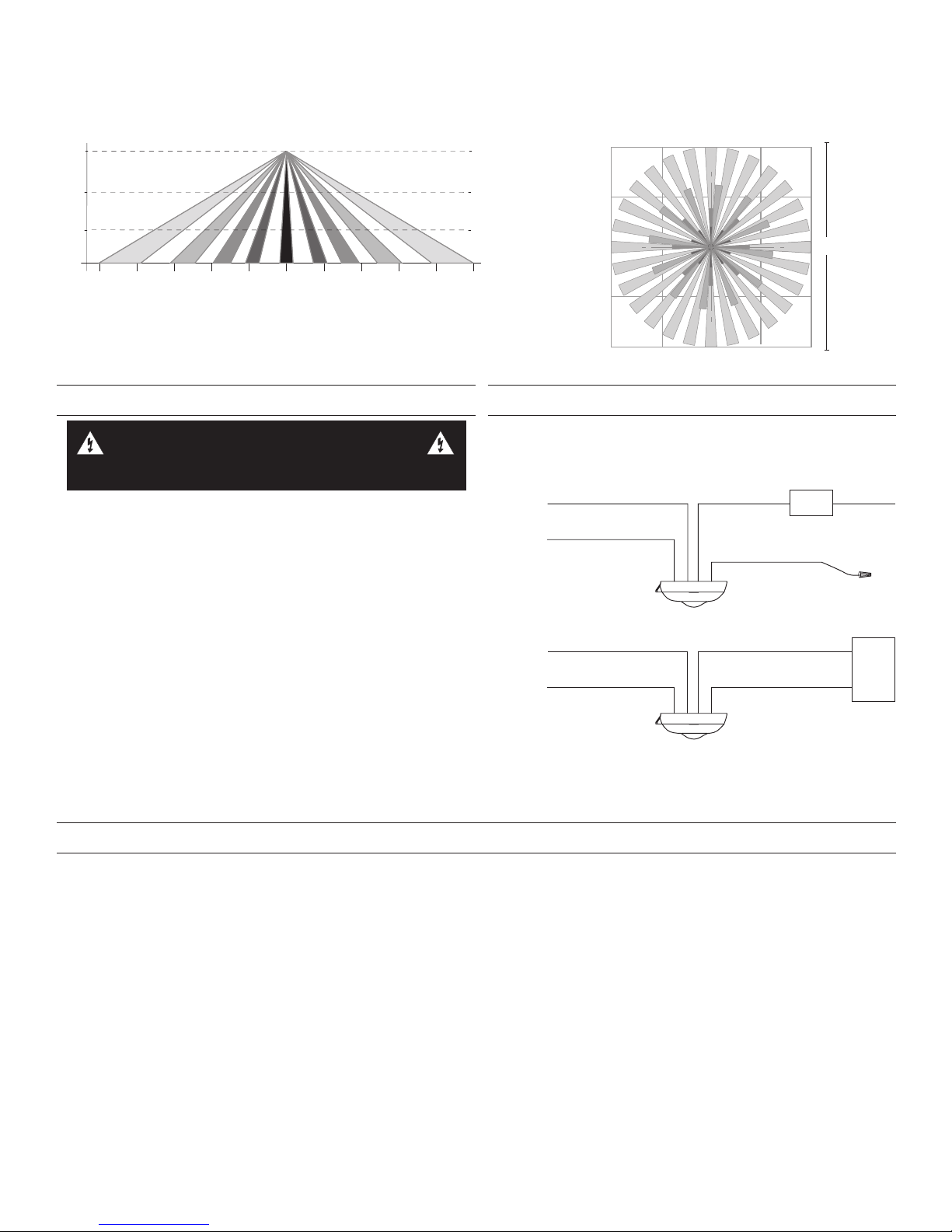
HBL1 Coverage Side View
40 30 20 10 010203040
20
10
10
20
20 ft
HBL1 Coverage Top View
&HLOLQJ
&RYHUDJH6LGH9LHZ
Coverage Top View
12 60612
®
High Bay • Line Voltage • Passive Infrared • Occupancy Sensor
No: 24162 – 2/17 rev. 1
Installation Instructions • Instructions d’Installation • Instrucciones de Instalación
Catalog Number • Numéro de Catalogue • Número de Catálogo: HB340B-L1, HB340B-L3, HB340B-L7
Country of Origin: Made in China • Pays d’origine: Fabriqué en Chine • País de origen: Hecho en China
SPECIFICATIONS
HB340B-Lx
Voltages ........................................................ 347/480VAC, 60Hz
Load requirementst
@347VAC, 60Hz ...............................................0-1200W ballast
@480VAC, 60Hz ................................................0-1200W ballas
HB340B-L1
HB340B-L3
HB340B-L7
@120VAC, 60Hz ...............................................................1/6 hp
Lens
L1 40 ft. mounting height, 60 ft. x 20 ft.
L3 20 ft. mounting height, 24 ft. diameter
L7 40 ft. mounting height, 100 ft. diameter
US Patent: ........................................... 5,640,113 and 5,804,991
DESCRIPTION AND OPERATION
The HB340B-Lx occupancy sensors are designed for automatic lighting control in warehouse high bay applications. All models contain a
passive infrared sensor (PIR). The HB340B-Lx series sensors are modular and are made up of a Power Module and a Lens. The coverage
area is determined by the lens module. There are three different lens available. See the Coverage section for more information.
All models in the HB340B-Lx series use a set of DIP switches to set the time delay and PIR sensitivity, as explained on page 3.
COVERAGE
Coverage patterns, density and range, are determined by the type of Lens attached to the HB340B-Lx.
HB340B-L1 and HB340B-L1M
The L1 Lens offers linear patterns best suited
for high bay aisleway applications. The
Fresnel lens is designed to detect walking
motion when mounted at or around 40’. In
optimal conditions, the lens has a 60’ linear
detection range.
Identical to the HBL1, the HBL1M comes
with opaque adhesive tape applied to the
interior of the lens, cutting off 1/2 of the
coverage pattern. This customized coverage
is ideal for the beginning of aisle ways where
cross traffic could be an issue.
HB340B-L3
The L3 Lens offers 360° coverage and is best suited
for open area and aisleway coverage in high bay
applications. The L3 is a multi-cell, multi-tier Fresnel
lens offering a high density coverage pattern that
spreads over a 24’ diameter area at a height of 20’.
0
10
20
30
40
0
Top View
12
6
6
0
24 ft
12
Page 2
e
HB340
HB340B-L7
50' 25' 0' 25' 50'
50'
25'
25'
50'
0'
0'
50'
The HBL7 lens is designed for higher mounting than the HBL3. The HBL7 has a lens that covers a 100’ diameter area at a height of 40’.
Ceiling
15'
27'
40'
50'
10' 10'20' 20'30' 30'40' 40'
Side View
INSTALLATION
WARNING
TURN THE POWER OFF AT THE CIRCUIT
BREAKER BEFORE INSTALLING THE SENSOR.
1. Determine the mounting location appropriate to the features
of the power module and the coverage area. Careful
consideration must be given to sensor placement. Avoid
placing the sensor where the edge of the fixture, shelving or
other obstructions may block the sensor’s line of sight. Mount
the sensor below the edge of the fixture and away from the
fluorescent lamps so that the heat from the lamps does not
affect the sensor.
2. Make sure that you have the appropriate accessories for the
sensor mounting configuration. (See Mounting Options.)
3. Assemble any necessary mounting accessories and attach
them to the power module, making sure that the flying leads
from the power module are accessible.
4. Connect the line voltage and load wires to the sensor leads as
shown in the Wiring Diagram for the unit’s application.
• Do not allow bare wire to show.
• Make sure all connections are secure.
5. Restore power from the circuit breaker.
347VAC Wiring
Line
Neutral
Black with White Stripes
480VAC Wiring
Phase A
Phase B
Black with White Stripes
Top View
0'
100'
WIRING
Black
Black
Red (Load A)
Red with White Stripes (Load B)
Red (Load A)
Red w/White Stripes (Load B)
Load
Cap the wir
Neutral
Load
The HB340B-Lx can be attached to the fixture or junction box using the back box and chase nipple or directly to the fixture surface via
the two screw holes provided in the Power Module (see Surface mounting below). The Extender Module (HBEM3) allows attaching the
sensor to the side of the fixture in a number of configurations using provided chase nipples.
Back box mounting requires a standard 1/2” knockout for the chase nipple. The Power Module mounts to the back box with a bayonet
type fitting requiring a slight twist of the units to separate them or lock them into place. The box comes ready for side mounting. It can
be modified for rear mounting as follows:
1. Pop out the cap in the rear knockout.
2. Un-snap the chase nipple from the side mount and snap into the rear mounting hole.
3. Use the cap to close the side mount hole.
4. The chase nipple provided can be pushed into a standard 1/2” knockout in a metal fixture [max of 1 mm (0.04”) thick metal] without
the need for the included internal nut. The nut can be used for added security if necessary.
The HBEM3 extender module allows threading the wires through its chase nipples and into the fixture for connection. The two sides of
the HBEM3 are then snapped together to protect the wires. The short chase nipple is designed to snap into the HBNB3 connection box
while the longer chase nipple snaps into any metal fixture or connection box with a standard knockout. The caps on the HBEM3 can be
removed in various configurations to allow moving the chase nipples and adjusting the height of the sensor on the fixture
Surface mounting requires holes in the fixture to pass wires and attach two #6-32 screws through the surface mounting screw holes on
the component side of the Power Module as shown.
MOUNTING OPTIONS
2
Page 3

HB340
HBLx
Lens
(do not touch)
Sensor
Module
Back
Box
HBEM3
Extender
Module
or
E
S
O
L
C
O
P
E
N
DIP Switches
Alignment Guides
Light Level
Adjustment
Trimpot
Using the back box and HBEM3 Extender Module
ADJUSTMENTS
Sensor factory pre-sets are as follows (default settings are bold):
Factory Switch Settings (N/A = not applicable, no effect)
1 2 3 4 5 6 7 8 9 10
ON OFF OFF OFF OFF ON ON OFF N/A N/A
PIR Sensitivity (switches 1&2) ........... Medium 85%
Time Delay (switches 3-7) ....................15 minutes
Override (switch 8) ........ Controlled by occupancy
PIR Sensitivity (Switches 1-2)
The factory setting (Normal) is suitable for most
applications, but it may be necessary to adjust the PIR
sensitivity if there is any environmental interference
causing false triggers or if sensitivity needs to be
increased for your particular application. Use DIP
switches 1 & 2 to adjust sensitivity.
Surface
Mounting
Screw Hole
Surface
Mounting
Screw Hole
PIR Sensor
Detection
Indicator LED
Time Delay (Switches 3-7)
Use DIP switches 3 to 7 to adjust the time delay.
Switch 3 4 5 6 7 TIME DELAY
ON ON ON ON ON 15 seconds
OFF ON ON ON ON 5 minutes
OFF OFF ON ON ON 10 minutes
OFF OFF OFF ON ON 15 minutes
OFF OFF OFF OFF ON 20 minutes
OFF OFF OFF OFF OFF 30 minutes
PIR Override (Switch 8)
A value of OFF enables occupancu control. A value of ON sets
the load ON all the time (used for testing load).
NOTE: Switches 9 and 10 are not used in this model.
Switch 1 2 PIR SENSITIVITY
OFF OFF 100% High
ON OFF 85% (MEDIUM)
OFF ON 75% (LOW)
ON ON 60% (LOW)
3
Page 4

IMPORTANT START-UP INFORMATION
A 60-second start-up period occurs during initial installation and after a power failure of 5 minutes or more. After applying power to the
sensor wait at least 60 seconds for the sensor to begin detecting occupancy and the load to turn ON. It may turn ON during the start-up
period, depending on the state of the relay when power was off.
• If the sensor detects occupancy during the start-up, when the load turns ON it stays ON as long as the sensor continues to detect
motion, plus the Time Delay.
• If no occupancy is detected during the 60-second start-up, the load may come on anyway during the start-up. If no occupancy is
detected by the time the start-up is complete, the relay opens and the load turns OFF.
TROUBLESHOOTING
If you suspect improper operation, review the Start-Up information. After start-up, the sensor will open or close the relay to correspond to
the occupancy status of the area. When power to the sensor is lost, the relay(s) close, turning on the load if the load still has power.
To quickly test the unit, set the time delay to minimum. Wait for the start-up period to end. Move out of the sensor’s view. Lights should
turn OFF after 15 seconds. Move into the sensor’s view. The sensor’s Red LED should blink and the lights should turn ON.
Red LED on power module does not blink:
Check sensor wire connections. Verify the neutral wire is tightly secured.
Red LED blinks but lights do not turn ON:
1. Make sure that power to the sensor has been ON continuously for at least one minute, then
a. Turn OFF power to the sensor. The relay will close.
b. Turn ON power to the sensor. The load should come ON. If not, continue with step 2.
2. Check power connections to the light fixture.
3. Check all sensor wire connections. Verify the load wire is tightly secured.
4. Make sure the sensor is not continuously triggered (LED Flashing) during the time delay duration.
Lights will not turn OFF:
1. If there is no motion from people or equipment in the sensor’s view but the red LED blinks, look for any nearby source of infrared
energy (heat) in motion, such as turbulent air from a heating or cooling supply, or other sources such as heat from the fluorescent
lamps in the fixture.
• Mount the sensor so that it’s lens is below the edge of the fixture and does not directly view the lamps.
• Divert the air supply away from the sensor, or move the sensor.
2. Verify time delay set in switches 3-7. The time delay can be set from 15 seconds to 30 minutes. Ensure that the time delay is set to
the desired delay and that there is no movement within the sensor’s view for that time period.
3. Check PIR and Light Level Override DIP switch settings. If all control functions are overridden the load stays ON.
4. Check sensor wire connections. Verify load and neutral wires are secure.
ORDERING INFORMATION
Catalog # Description
HB340B-L1 High Bay Sensor 347/480 VAC with coverage @ 40’ mounting height, 60’ x 20’.
HB340B-L3 High Bay Sensor 347/480 VAC with coverage @ 20’ mounting height, 24’ diameter.
HB340B-L7 High Bay Sensor 347/480 VAC with coverage @ 40’ mounting height, 100’ diameter.
HB3EM3 Extender module with 2 chase nipples and nuts 1 short (0.88”) for connection to plastic, 1 long (1.24”) for
connection to metal
All units are White.
WARRANTY INFORMATION INFORMATIONS RELATIVES À LA GARANTIE INFORMACIÓN DE LA GARANTÍA
Wattstopper warranties its products to be free
of defects in materials and workmanship for a
period of five (5) years. There are no obligations
or liabilities on the part of Wattstopper for
consequential damages arising out of, or in
connection with, the use or performance of this
product or other indirect damages with respect
to loss of property, revenue or profit, or cost of
removal, installation or reinstallation.
No. 24162 – 2/17 rev. 1
© Copyright 2017 Legrand All Rights Reserved.
© Copyright 2017 Tous droits réservés Legrand.
© Copyright 2017 Legrand Todos los derechos reservados.
Wattstopper garantit que ses produits sont
exempts de défauts de matériaux et de fabrication
pour une période de cinq (5) ans. Wattstopper
ne peut être tenu responsable de tout dommage
consécutif causé par ou lié à l’utilisation ou
à la performance de ce produit ou tout autre
dommage indirect lié à la perte de propriété, de
revenus, ou de profits, ou aux coûts d’enlèvement,
d’installation ou de réinstallation.
Wattstopper garantiza que sus productos
están libres de defectos en materiales y mano
de obra por un período de cinco (5) años. No
existen obligaciones ni responsabilidades por
parte de Wattstopper por daños consecuentes
que se deriven o estén relacionados con el
uso o el rendimiento de este producto u otros
daños indirectos con respecto a la pérdida
de propiedad, renta o ganancias, o al costo
de extracción, instalación o reinstalación.
800.879.8585
www.legrand.us/wattstopper
 Loading...