

Page 1

FSIR-100
Wireless IR Configuration Tool
User Guide
CONTENTS
Using The FSIR-100 Configuration Tool ........................... 1
Batteries .......................................................................... 1
Navigation ....................................................................... 2
FSP-211 .......................................................................... 2
IR Communication ........................................................... 2
FSP-211 Screens ............................................................. 3
Home Menu ...................................................................3
New Settings .................................................................3
Current Settings ............................................................5
Test Mode ......................................................................5
Recall Profiles ...............................................................6
HBP-111 .......................................................................... 7
HBP-111 Screens ............................................................. 8
Home Menu ...................................................................8
New Settings .................................................................8
Current Settings ............................................................9
Test Mode ....................................................................10
Load Toggle .................................................................10
Recall Profile ...............................................................10
Troubleshooting..............................................................10
USING THE FSIR100 CONFIGURATION TOOL
The FSIR-100 Wireless IR Configuration Tool is a handheld
tool for changing defaults and testing of WattStopper
devices.It provides wireless access to the devices for
parameter changes and testing.
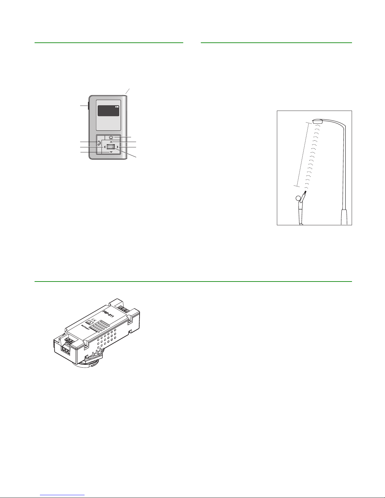
The FSIR-100 display shows menus and prompts to lead
you through each process. The navigation pad provides a
simple way to navigate through the customization fields.
Within a certain mounting height of the sensor, the FSIR100 allows modification of the system without requiring
ladders or tools; simply with a touch of a few buttons.
The FSIR-100 IR transceiver allows bi-directional
communication between the device and the FSIR-100
configuration tool . Simple menu screens let you see
the current status of the sensor and make changes. It
can change device parameters such as high/low mode,
sensitivity, time delay, cut off and more. With the FSIR-100
you can also establish and store device parameter profiles.
BATTERIES
The FSIR-100 operates on three
standard 1.5V AAA Alkaline batteries
or three rechargeable AAA NiMH
batteries. The battery status displays
in the upper right corner of the
display. Three bars next to BAT=
indicates a full battery charge. A
warning appears on the display when the battery level falls
below a minimum acceptable level. To conserve battery
power, the FSIR-100 automatically shuts off 10 minutes
after the last key press.
• If communication is not successful, (if possible) move
closer to the sensor.
• If still not successful, there may be too much IR
interference from other sources. Programming the
unit at night when there is no daylight available may
be the only way to communicate with the sensor.
Page 2
NAVIGATION
IR COMMUNICATION
Navigate from one field to another using (up) or (down)
arrow keys. The active field is indicated by flashing
(alternates) between yellow text on black background and
black text on yellow background.
IR tx/rx
Power
On/Off
Back
Left
Down
FSP-211
HBP-111
BAT=
Home/Main
Menu
Up
Right/Next
Select
Once active, use the Select button to move to a menu or
function within the active field. Value fields are used to
adjust parameter settings. They are shown in “less-than/
greater-than” symbols: <value>. Once active, change them
using(left) and(right) arrow keys. The right key increments
and the left key decrements a value. Selections wraparound if you continue to press the key beyond maximum
or minimum values. Moving away from the value field
overwrites the original value. The Home button takes you
to the main menu. The Back button can be thought of as an
undo function. It takes you back one screen. Changes that
were in process prior to pressing the key are lost.
IR communication can be affected by the mounting height of
the sensor and high ambient lighting such as direct daylight
or electric light such as floodlights, and some halogen,
fluorescent lamps, LED’s.
When trying to communicate with the device, be sure to be
positioned under the sensor without any obstructions. Every
time the commissionng tool establishes communication with
the device, the controlled load will cycle.
15'-30'
* Distance may vary depending on the
lighting environment
FSP211
14-18 AWG Soli
LOAD
FSP-211
High/Low PIR
LINE
Occupancy Sensor
230 VAC, 50 Hz
d CU Wire Only
1200W max ballast
5E4
800.879.8585
www.wattstopper.com
Class 2 Wiring Only
18-20 AWG Solid CU Wire Only
GRND
15195r1
DIM-
(grey)
DIM+
(violet)
The FSP-211 is a motion sensor that dims lighting from high to low based on movement. This slim, low-profile sensor is
designed for installation inside the bottom of a light fixture body. The PIR lens module connects to the FSP-211 through a 1.30”
diameter hole in the bottom of the fixture.
The sensors use passive infrared (PIR) sensing technology that reacts to changes in infrared energy (moving body heat) within
the coverage area. Once the sensor stops detecting movement and the time delay elapses lights will go from high to low mode
and eventually to an OFF position if it is desired. Sensors must directly “see” motion of a person or moving object to detect
them, so careful consideration must be given to sensor luminaire placement and lens selection. Avoid placing the sensor where
obstructions may block the sensor’s line of sight.
NEUT
Call 800-879-8585 for Technical Support
Page 3
Select
FSP-211
Select
r
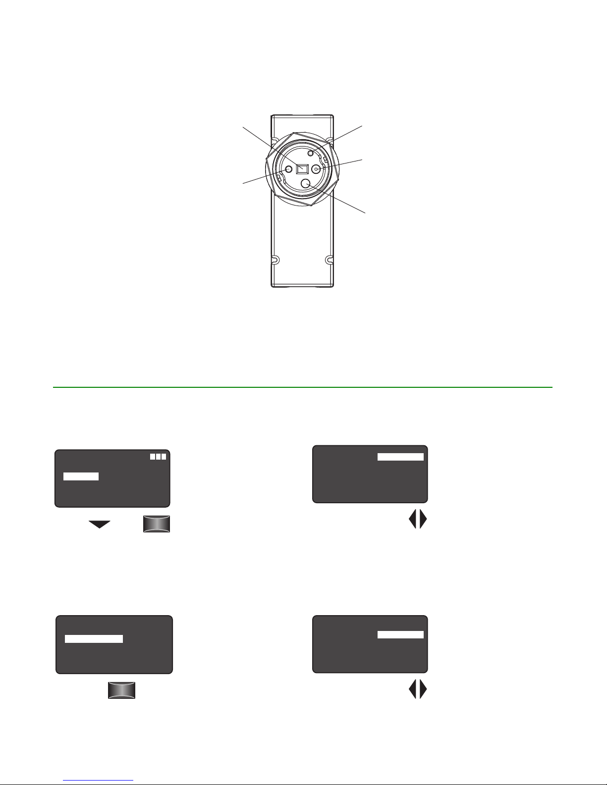
Motion Indicator
Red LED
COMPONENTS
FSP211 SCREENS
PIR Sensor
Light Sensor
IR Transmitte
IR Receiver
Home Menu
Choose
New Settings
BAT
FSP-211
HBP-111
Press
Sensor Configuration
New Settings
Current Settings
Test Mode
Recall Profiles
FSP-211
NEXT
Press
High Mode
=
The Home (or Main) menu
displays after the powerup process completes. It
contains information on the
battery status and sensor
menu choices. Press the up
or down buttons to highlight
the desired sensor then
FSP-211 Settings
High Mode:
Low Mode:
Time Delay:
Cut Off:
Sensitivity:
Setpoint:
NEXT SEND
Press the Left/Right Arrow
to Increase or Decrease Volts
<10 Volts>
<1 Volts>
<5 Min>
<1 hour>
<Max>
< Dis>
press Select.
To program the FSP-211 with the selected parameters go
to SEND and press the Select button. The controlled load
should cycle once the sensor is updated.
When the sensor detects
motion the dimming control
output ramps up to the
selected HIGH light level
(default is 10V).
Range: 0 V to 10 V
Increments: 0.2 V
Low Mode
New Settings allow you to
select the different sensor
parameters such as: High/
Low Mode, Time Delay, Cut
Off, Sensitivity, Setpoint and
Ramp/Fade rates.
FSP-211 Settings
High Mode:
Low Mode:
Time Delay:
Cut Off:
Sensitivity:
Setpoint:
NEXT SEND
Press the Left/Right Arrow
to Increase or Decrease Volts
<10 Volts>
<1 Volts>
<5 Min>
<1 hour>
<Max>
< Dis>
After the sensor stops
detecting motion and the
time delay expires the
dimming control output
fades down to the selected
LOW light level (default is
1V).
Range: OFF, 0 V to 9.8 V
Increments: 0.2 V
Visit our web site for FAQs: www.wattstopper.com
Page 4

More Settings
Time Delay
Pr
to Choose PRIOR
FSP-211 Settings
High Mode:
Low Mode:
Time Delay:
Cut Off:
Sensitivity:
Setpoint:
NEXT SEND
Press the Left/Right Arrow
to Raise or Lower Time Delay
<10 Volts>
<1 Volts>
<5 Min>
<1 hour>
<Max>
< Dis>
The time period that must
elapse after the last time
the sensor detects motion
for the lights to fade to LOW
mode (default is 5 min).
Range: 30 sec, 1 min to 30 min
Increments: 1 min
Next
FSP-211 Settings
High Mode:
Low Mode:
Time Delay:
Cut Off:
Sensitivity:
Setpoint:
NEXT SEND
Choose NEXT to View
<10 Volts>
<1 Volts>
<30 Sec>
<1 hour>
<Max>
< Dis>
To view more settings go to
NEXT and press the Select
button
Cut Off
FSP-211 Settings
High Mode:
Low Mode:
Time Delay:
Cut Off:
Sensitivity:
Setpoint:
NEXT SEND
ess the Left/Right Arrow to
Increase or Decrease Cut Off
<10 Volts>
<1 Volts>
<5 Min>
<1 hour>
<Max>
< Dis>
Increments: 1 min or 1 hr
The time period that must
elapse after the lights fade
to Low Mode and the sensor
detects no motion for the
lights to turn OFF (default is
1 hour).
Range: Disable (No cut off,
lights will stay in low mode)
1 min to 59 min, 1 hr to 5 hr
(press and hold should cause
to move faster through the
increments)
Sensitivity
FSP-211 Settings
High Mode:
Low Mode:
Time Delay:
Cut Off:
Sensitivity:
Setpoint:
NEXT SEND
Press the Left/Right Arrow
to Increase or Decrease
Sensitivity
<10 Volts>
<1 Volts>
<5 Min>
<1 hour>
<Max>
< Dis>
The response of the PIR
detector to motion within
the sensor’s coverage area
(default is max).
Range and Sequence: On-Fix,
Off-Fix, Low, Med, Max
(On-Fix: relay closed,
occupancy detection
disabled; Off-Fix, relay open,
occupancy detection disabled.
Hold Off Setpoint
FSP-211 Settings
High Mode:
Low Mode:
Time Delay:
Cut Off:
Sensitivity:
Setpoint:
NEXT SEND
Press the Left/Right Arrow
to Increase or Decrease
Setpoint
<10 Volts>
<1 Volts>
<5 Min>
<1 hour>
<Max>
< Dis>
The Auto option invokes an automatic calibration procedure
to establish an appropriate setpoint based upon the
contribution of the electric light. As part of this procedure,
the controlled load is turned on to warm up the lamp, and
then it is switched off and on eight times, terminating in
an off state. After this process, a new setpoint value is
automatically calculated. During this time, communication to
the FSP-211 is disabled.
The selectable ambient light
level threshold that will hold
the lights off or at LOW level
when the sensor detects
motion (default is Disable).
Range: Auto, Disable, 1 fc to
250 fc
Increments: 1 fc (press and
hold should cause to move
faster thru the increments)
Sequence: Disable, 1 fc to
250 fc
Ramp Up
FSP-211 Settings
Ramp Up:
Fade Down:
Photocell:
PRIOR SAVE SEND
Press the Left/Right Arrow to
Increase or Decrease Sec
< Dis>
< Dis>
< Dis>
Time period for light level to
increase from LOW to HIGH
(default is Disable; light/load
switches instantly).
Range: Disable, 1 sec to 60 sec
Increments: 1 sec
Fade Down
FSP-211 Settings
Ramp Up:
Fade Down:
Photocell:
PRIOR SAVE SEND
Press the Left/Right Arrow to
Increase or Decrease Sec
< Dis>
< Dis>
< Dis>
Time period for light level to
decrease from HIGH to LOW
(default is Disable; light/load
switches instantly).
Range: Disable, 1 sec to 60 sec
Increments: 1 sec
Photocell On/Off
FSP-211 Settings
Ramp Up:
Fade Down:
Photocell:
PRIOR SAVE SEND
< Dis>
< Dis>
< Dis>
in order to confirm the light level increase is not temporary
before forcing the lights to go off. When light level goes
below the settings, the light will turn on even without motion
detection. This feature is disabled by default. If using this
setting in combination with the Hold Off setpoint, there must
be at least 10fc of dead band between the two settings. The
Photocell setpoint is automatically set to maintain at least
10fc of dead band above the Hold Off setpoint to help avoid
load cycling.
When the light level exceeds
this setting, the lights will
turn off even when the space
is occupied. Once the light
level exceeds this setting, the
sensor will wait and monitor
for a short period of time
Prior
FSP-211 Settings
Ramp Up:
Fade Down:
Photocell:
PRIOR SAVE SEND
Press the
Down Arrow
< Dis>
< Dis>
< Dis>
Press
Select
To go back to previous
settings go to PRIOR and
press the Select button.
Call 800-879-8585 for Technical Support
Page 5

Send
Pr
to Choose Profile
to Choose PRIOR
to Choose SEND
to Choose DONE
Select
Test Mode
FSP-211 Settings
Ramp Up:
Fade Down:
Photocell:
PRIOR SAVE SEND
Press the Down Arrow
< Dis>
< Dis>
< Dis>
To program the
FSP-211 with the selected
parameters go to SEND and
press the Select button.
The controlled load should
cycle once the sensor is
updated.
Light Level
FSP-211 Settings
Ramp Up:
Fade Down:
Light Level:
Photocell:
PRIOR SAVE
< Dis>
< Dis>
<15>
< Dis>
DONE
Displays the light level
at the FSP-211. The light
level reading can be used
as a reference for setpoint
adjustments.
Save
FSP-211 Settings
Ramp Up:
Fade Down:
Photocell:
PRIOR SAVE DONE
Press the
Down Arrow
to Choose SAVE
Save FSP-211 Parms
Save FSP-211 Parms
Up/Down Arrow
Press the
Profile 1
Profile 2
Profile 3
Profile 4
Profile 5
Profile 6
Cancel
Press
Select
Press
Select
< Dis>
< Dis>
< Dis>
To Save these New
Settings parameters
as one of the profiles
go to SAVE and press
the Select button.
Current Settings
Sensor Configuration
FSP-211
New Settings
Current Settings
Test Mode
R ecall Profiles
Choose
Current
Settings
Press
Select
Point to desired
Occupancy Sensor
Press ‘Select’
Point and
Press Select
Current Settings allow you to recall the parameters for a
specific sensor. These are read only parameters.
View Current Settings
FSP-211 Settings
High Mode:
Low Mode:
Time Delay:
Cut Off:
Sensitivity:
Setpoint:
NEXT DONE
Press Select to
View More Settings
FSP-211 Settings
Ramp Up:
Fade Down:
Light Level:
Photocell:
PRIOR SAVE
<10 Volts>
<1 Volts>
<5 Min>
<1 hour>
<Max>
< Dis>
DONE
Highlight and press
Select to view the Current
Settings.
To go back to previous
Dis
settings go to PRIOR and
Dis
press the Select button.
15
Dis
Done
FSP-211 Settings
Ramp Up:
Fade Down:
Light Level:
Photocell:
PRIOR SAVE DONE
Press the Down Arrow
Test Mode
Sensor Configuration
Choose
FSP-211
NEXT
Press
New Settings
Current Settings
Test Mode
Recall Profiles
Enable/Disable
FSP-211 Test Mode
Enable Disable
ess the Left/Right
Arrow to Enable or
Disable Test Mode
< Dis>
< Dis>
<15>
< Dis>
Press
Select
To go to the FSP-211
Home screen go to DONE
and press the Select
button.
Test Mode shortens
timeouts for High/Low
and Cut Off, to allow quick
verification of settings.
Test Mode disables
automatically after 5
minutes.
Test Mode has been
enabled.
Press the Down Arrow
Visit our web site for FAQs: www.wattstopper.com
Page 6

Recall Profiles
Select
Select
Recall Profiles
Select
NEXT SEND
Sensor Configuration
Choose
Press the
FSP-211
NEXT
Profile 1
Profile 2
Profile 3
Profile 4
Profile 5
Profile 6
Cancel
Press
<10 Volts>
<1 Volts>
<30 Sec>
<1 hour>
New Settings
Current Settings
Test Mode
Recall Profiles
Recall FSP-211 Parms
Up/Down Arrow
to Choose a
Specific Profile
FSP-211 Settings
High Mode:
Low Mode:
Time Delay:
Cut Off:
Sensitivity:
Setpoint:
Press
Select
<Max>
< Dis>
Recall Profiles allow
the user to select
the saved parameter
profiles. This feature
is used when
programming multiple
FSP-211’s with the
same parameters.
Selecting a specific
profile allow the user
to also change the
parameters such
as: High/Low Mode,
Time Delay, Cut Off,
Sensitivity, Setpoint
and Ramp/Fade rates.
Lock Settings
IR communication locks to prevent unauthorized changes of
FSP-211 parameters.
Sensor Configuration
FSP-211
New Settings
Current Settings
Test Mode
R ecall Profiles
NEXT
Press
Sensor Configuration
FSP-211
Lock Settings
PRIOR
Press
Lock Settings
FSP-211
Lock Delay <Disable>
To view more sensor
configuration settings go to
NEXT and press the Select
button.
FSP-211 default settings
communicate with the
FSIR-100; however, this
security feature limits
communication only for
authorized installers who
have access to main power
supply to the FSP-211
sensor. Press Select to set
Lock Delay or press PRIOR
to go back.
PRIOR
Press the Left/Right Arrow
to Disable or set Lock
Delay time
SEND
Factory default Lock Delay setting is disabled and FSP-211
parameter can change with any FSIR-100 at anytime. To
enable Lock Delay with time, select lock delay time and press
SEND to set delay time in the FSP-211. Its parameter changes
with the FSIR-100 will be locked after the specified timer
expires from the last message. At the end of the specified time
the FSP-211 will be locked unless there is a power cycle. Any
locked sensor needs power cycling to initiate any configuration
through the FSIR-100. To permanently disable Lock Delay after
power cycling, select Disable and press SEND.
Range: 10 min - 240 min
Increments: 1 min
Lock Settings
FSP-211
Lock Delay <10 min>
PRIOR
Press
Select
SEND
Highlight SEND and
press Select to enable
lock settings.
FSP-211
SENSOR IS LOCKED
Call 800-879-8585 for Technical Support
This screen will appear
if the FSP-211 is locked.
If it is locked, cycle the
power.
Page 7

HBP111
PIR Sensor
Push Button
The HBP High Bay Passive Infrared (PIR) Occupancy Sensor consists of two components. These components were developed
to work as a convenient system and include both sensor and lens modules. HBP-111 sensor is designed for automatic lighting
control in warehouses and other indoor high bay spaces. The lens is specifically engineered to provide reliable coverage
from a wide range of mounting heights. Time Delay and Light Level settings for the HBP sensor can be adjusted via trimpots
designated for each. The HBP-111 can also be commisioned remotely using a wireless configuration tool.
The HBP occupancy sensor is designed to mount directly to a light fixture and control the load in the fixture. It can be wired to
control all ballasts in the fixture. When motion is detected within the sensor’s coverage area, the relay in the sensor closes, and
lighting loads are automatically turned on. When motion is no longer detected for the duration of the time delay setting, the
relay opens and the lighting load is turned off. The sensor’s light level hold-off and time delay settings are factory preset at 300
foot candles and 15 minutes, respectively, which are suitable for most high bay applications.
COMPONENTS
IR
Transmitter
IR
Receiver
Detection
Indicator LED
(do not touch)
Light Level
Adjustment
Trimpot
Time Delay
Adjustment
Trimpot
Visit our web site for FAQs: www.wattstopper.com
Page 8

Select
HBP-111
Sensitivity
Set point
Burn-In
Walk-through
Visual Alert
HBP111 SCREENS
Home Menu
The Home (or Main) menu
BAT
=
displays after the powerup process completes. It
FSP-211
HBP-111
contains information on the
battery status and sensor
menu choices. Press
the up or down buttons
Choose
Press
to highlight the desired
sensor then press Select.
New Settings
HBP-111 Configuration
New Settings
Current Settings
Test Mode
Load Toggle
Recall Profile
Press
Select
New Settings allow you to
select the different sensor
parameters such as: Time
Delay, Sensitivity, On Set
point and Burn-In Mode.
Time Delay
HBP-111 Settings
Time Delay:
Sensitivity:
On Set point:
Burn-In Mode:
Walk-through:
Visual Alert:
NEXT SEND
Press the Left/Right Arrow
to Raise or Lower Time Delay
<15 Mins>
<Max>
< Dis>
< Dis>
< Dis>
< Dis>
To program the HBP-111 with the selected parameters go
to SEND and press the Select button. The controlled load
should cycle once the sensor is updated.
The time period that must
elapse after the last time
the sensor detects motion
for the lights (default is 15
min).
Range: 1 min to 30 min
Increments: 1 min
Sensitivity
HBP-111 Settings
Time Delay:
Sensitivity:
On Set point:
Burn-In Mode:
Walk-through:
Visual Alert:
NEXT SEND
Press the Left/Right Arrow
to Increase or Decrease
<15 Mins>
<Max>
< Dis>
< Dis>
< Dis>
< Dis>
The response of the PIR
detector to motion within
the sensor’s coverage area
(default is max).
Range and Sequence:
Low, Med, Max
On Set point
HBP-111 Settings
Time Delay:
Sensitivity:
On Set point:
Burn-In Mode:
Walk-through:
Visual Alert:
NEXT SEND
Press the Left/Right Arrow
to Increase or Decrease
<15 Mins>
<Max>
< Dis>
< Dis>
< Dis>
< Dis>
Burn-In Mode
HBP-111 Settings
Time Delay:
Sensitivity:
On Set point:
Burn-In Mode:
Walk-through:
Visual Alert:
NEXT SEND
Press the Left/Right Arrow
to Enable or Disable
<15 Mins>
<Max>
< Dis>
< Dis>
< Dis>
< Dis>
Walk-through Mode
HBP-111 Settings
Time Delay:
Sensitivity:
On Set point:
Burn-In Mode:
Walk-through:
Visual Alert:
NEXT SEND
Press the Left/Right Arrow
to Enable or Disable
<15 Mins>
<Max>
< Dis>
< Dis>
< Dis>
< Dis>
Visual Alert
HBP-111 Settings
Time Delay:
Sensitivity:
On Set point:
Burn-In Mode:
Walk-through:
Visual Alert:
NEXT SEND
Press the Left/Right Arrow
to Enable or Disable
<15 Mins>
<Max>
< Dis>
< Dis>
< Dis>
< Dis>
The selectable ambient light
level threshold that will hold
the lights off when the sensor
detects motion (default is 300
fc).
Range: Disabled, 1 fc to 300 fc
Increments: 1 fc (press and
hold should cause to move
faster thru the increments)
Default: Disabled
When burn-in is enabled,
the light load will turn On
for 100 hours and remain on
regardless of occupancy. The
push button on the HBP-111
can be used to toggle the
load and exit burn-in mode.
The FSIR-100 can also be
used to exit burn-in mode.
Default: Disabled
Walk-through mode provides
a 3 min time delay for
applications where occupancy
is brief, such as a copy room,
closet, etc. When enabled,
if no activitity is detected
after the first 30 sec from
initial trigger, the sensor
will turn the load off 3 min
after the initial detection. If
there is activity after the first
30 sec, the sensor will use
the set time delay. Once the
time delay has expired, the
sensor will revert to using the
standard walk-through mode
time delay Default is Off.
The sensor will toggle the load
for 1 sec alerting the occupant
that the set time delay will be
reached within 1 min and turn
the lighting off. This provides
a visual indication so that
the occupant can keep the
lights on by moving within the
coverage area if the space will
still remain occupied. Default
is Off.
Call 800-879-8585 for Technical Support
Page 9

Next
Occupancy Mode
to Choose PRIOR
to Choose Profile
Settings
Current Settings
HBP-111 Settings
Time Delay:
Sensitivity:
On Set point:
Burn-In Mode:
Walk-through:
Visual Alert:
NEXT
SEND
Press the Left/Right Arrow
to go to more settings
<15 Mins>
Service Mode
HBP-111 Settings
Service Mode:
PRIOR SAVE
Press the Left/Right Arrow
to Enable or Disable
SEND
Prior
HBP-111 Settings
Service Mode:
PRIOR SAVE
Press the
Down Arrow
SEND
Send
HBP-111 Settings
Service Mode:
PRIOR SAVE
Press the Down Arrow
to Choose SEND
SEND
Save
HBP-111 Settings
Service Mode: <Dis>
PRIOR SAVE SEND
<Max>
< Dis>
< Dis>
< Dis>
< Dis>
<Dis>
<Dis>
Press
Select
<Dis>
To view more settings go to
NEXT and press the Select
button
In Service Mode, motion
detection is disabled. If
you enable Service Mode,
loads must be turned ON
and OFF manually. When
disabled (the default), the
sensor functions normally.
To go back to previous
settings go to PRIOR and
press the Select button.
To program the HBP-111
with the selected parameters
go to SEND and press the
Select button. The controlled
load should cycle once the
sensor is updated.
To Save these New
Settings parameters as
one of the profiles go
to SAVE and press the
Select button.
HBP-111 Configuration
New Settings
Current Settings
Test Mode
Load Toggle
Recall Profile
Choose
Current
Press
Select
Point to desired
Occupancy Sensor
Press ‘Select’
Point and
Press Select
Current Settings allow you to recall the parameters for a
specific sensor. These are read only parameters.
View Current Settings
HBP-111 Settings
Time Delay:
Sensitivity:
On Set point:
Burn-In Mode:
Walk-through:
Visual Alert:
NEXT
SEND
Press the Left/Right Arrow
to go to more settings
<15 Mins>
<Max>
< Dis>
< Dis>
< Dis>
< Dis>
Highlight and press
Select to view the current
settings.
Light Level
HBP-111 Settings
Service Mode: <Dis>
Light Level: <200>
PRIOR SAVE DONE
Presents light level to the
HBP-111. The light level
reading can be used as
a reference for setpoint
adjustments.
To be able to Save
these Current Settings
parameters as one of the
profiles go to SAVE and
press the Select button.
Done
HBP-111 Settings
Service Mode: <Ena>
Light Level: <200>
PRIOR SAVE DONE
Press the Down Arrow
to Choose DONE
To be able to go to the
HBP-111 Home screen
go to DONE and press the
Select button.
Press the
Down Arrow
to Choose SAVE
Save FSP-211 Parms
Save HBP-111 Parms
Profile 1
Profile 2
Profile 3
Profile 4
Profile 5
Profile 6
Cancel
Press the
Up/Down Arrow
Press
Select
Press
Select
Visit our web site for FAQs: www.wattstopper.com
Page 10

Test Mode
Select
Test Mode
Pr
Select
Select
Recall Profile
Specific Profile
TROUBLESHOOTING
HBP-111 Configuration
New Settings
Current Settings
Test Mode
Load Toggle
Recall Profile
Choose
Enable/Disable
HBP-111 Test Mode
ENABLEENABLE DISABLE
ess the Left/Right
Arrow to Enable or
Disable Test Mode
Load Toggle
HBP-111 Configuration
New Settings
Current Settings
Test Mode
L oad Toggle
Recall Profile
Press
Point to desired
Occupancy Sensor
Press ‘Select’
Press
Press
Select
Test Mode shortens
the time delay to allow
quick verification of HBP
coverage for motion
detection. Test Mode
disables automatically
after 10 minutes.
Test Mode has been
enabled.
Used to turn the load
ON and OFF from the
FSIR-100.
When occupancy mode
is disabled, the light
will remain ON or OFF
depending on the last
state.
Options: ON, OFF
Default: ON
Problem: Display does not come on when I press the Power
On Button.
• Make sure the batteries are installed correctly.
• Make sure batteries are good.
Problem: No Response Screen appears:
No response
from device
Press ‘Select’
• Make sure that the device is not obstructed and try
again.
• Move closer to the device.
• The angle may be too high, move closer so that you are
directly underneath the sensor.
• If still not successful, there may be too much IR
interference from other sources. Programming the unit
at night when there is no daylight available may be the
only way to communicate with the sensor.
• Make sure you are using the FSIR-100 and not the
LMCT-100.
• Make sure the device is within range.
• Make sure the device you are pointing at is powered.
For other issues not related to communication, consult the
appropriate installation instructions or contact Technical
Support at 800.879.8585.
Point and
Press Select
Recall Profile
HBP-111 Configuration
New Settings
Current Settings
Test Mode
L oad Toggle
R ecall Profile
Choose
Recall HBP-111 Parms
Up/Down Arrow
to Choose a
Press the
Profile 1
Profile 2
Profile 3
Profile 4
Profile 5
Profile 6
Cancel
Press
Press
Select
Recall Profiles allow the
user to select the saved
parameter profiles. This
feature is used when
programming multiple
HBP-111’s with the same
parameters.
FSP-211 Settings
High Mode:
Low Mode:
Time Delay:
Cut Off:
Sensitivity:
Setpoint:
NEXT SEND
Call 800-879-8585 for Technical Support
Page 11

WARRANTY INFORMATION
WattStopper warranties its products to be free of defects in materials and workmanship for a period of five (5) years. There are
no obligations or liabilities on the part of WattStopper for consequential damages arising out of, or in connection with, the use
or performance of this product or other indirect damages with respect to loss of property, revenue or profit, or cost of removal,
installation or reinstallation.
2800 De La Cruz Boulevard,
Santa Clara, CA 95050
800.879.8585
www.wattstopper.com
19071r3
6/2015
Please
Recycle
 Loading...