

Page 1
Wiremold®electrical systems conform to and should be properly
grounded in compliance with requirements of the current National
Electrical Code or codes administered by local authorities.
All electrical products may present a possible shock or fire
hazard if improperly installed or used. Wiremold®electrical products
may bear the mark of a Nationally Recognized Testing Laboratory
(NRTL) and should be installed in conformance with current local
and/or the National Electrical Code.
FloorPort™Series
Activation Covers & Barrier Kits
I N S T A L L A T I O N I N S T R U C T I O N S
Installation Instruction No.: 1 008 150 R2 – Updated April 2011
Products: FP Series Covers with PKKIT, RFBKIT, RFBCIKIT, NRGKIT Barriers, & Abandonments S3AXPB, PKCAP and NRGCAP.
IMPORTANT: Please read all instructions
before beginning.
CAUTION: Do not operate floor scrubbers, tile strippers, or resurfacing equipment over the top of the cover. This may result in damage
CAUTION: Wash covers with a mild soap solution. Avoid any cleaning solutions with ingredients that may react with the aluminum
to the surface of the product.
construction of the products.
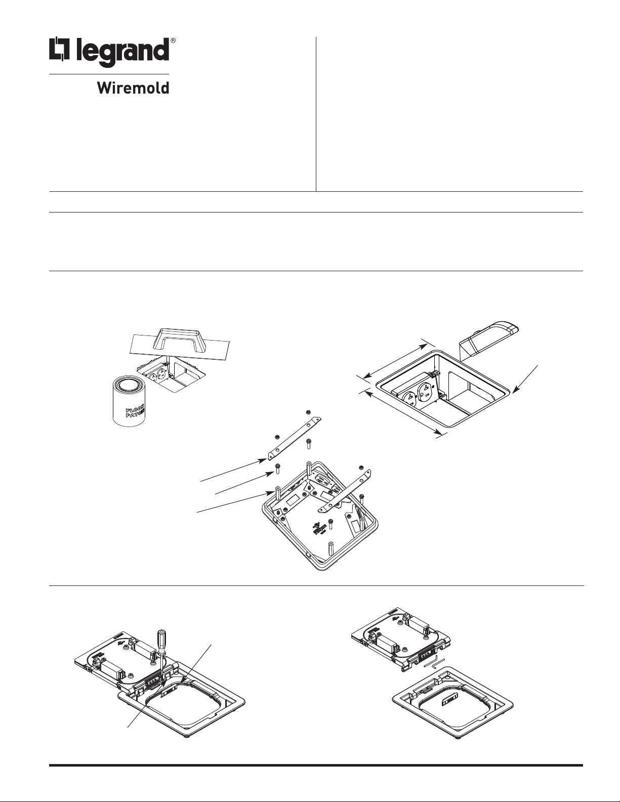
TRIM FLANGE INSTALLATION:
1. PREPARATION: Before installing Cover, repair any
cracks or chips around the Preset or Floor Box
opening using a suitable grout or repair compound.
3. RFB6 Installation Only – Install standoffs,
adjusting screws, and link straps as shown.
Link Strap
Adjusting Screw
Standoff
2. FPCTC, FPBTC & FPFFTC Series – Flanged Carpet
Installation Cut opening in Carpet as indicated in illustration.
6 1/4"
[158mm]
7 7/16"
[188mm]
Radius
1/2" [12.7mm]
1. REMOVING THE LID (FPC & FPB Series): Pry off
Cap from Hinge Clip with small blade screwdriver to
expose “L” Pins. Roll “L” Pin down and slide inward.
Cap
“L” Pin
1a. Remove both “L” Pins and detach Lid.
Page 2
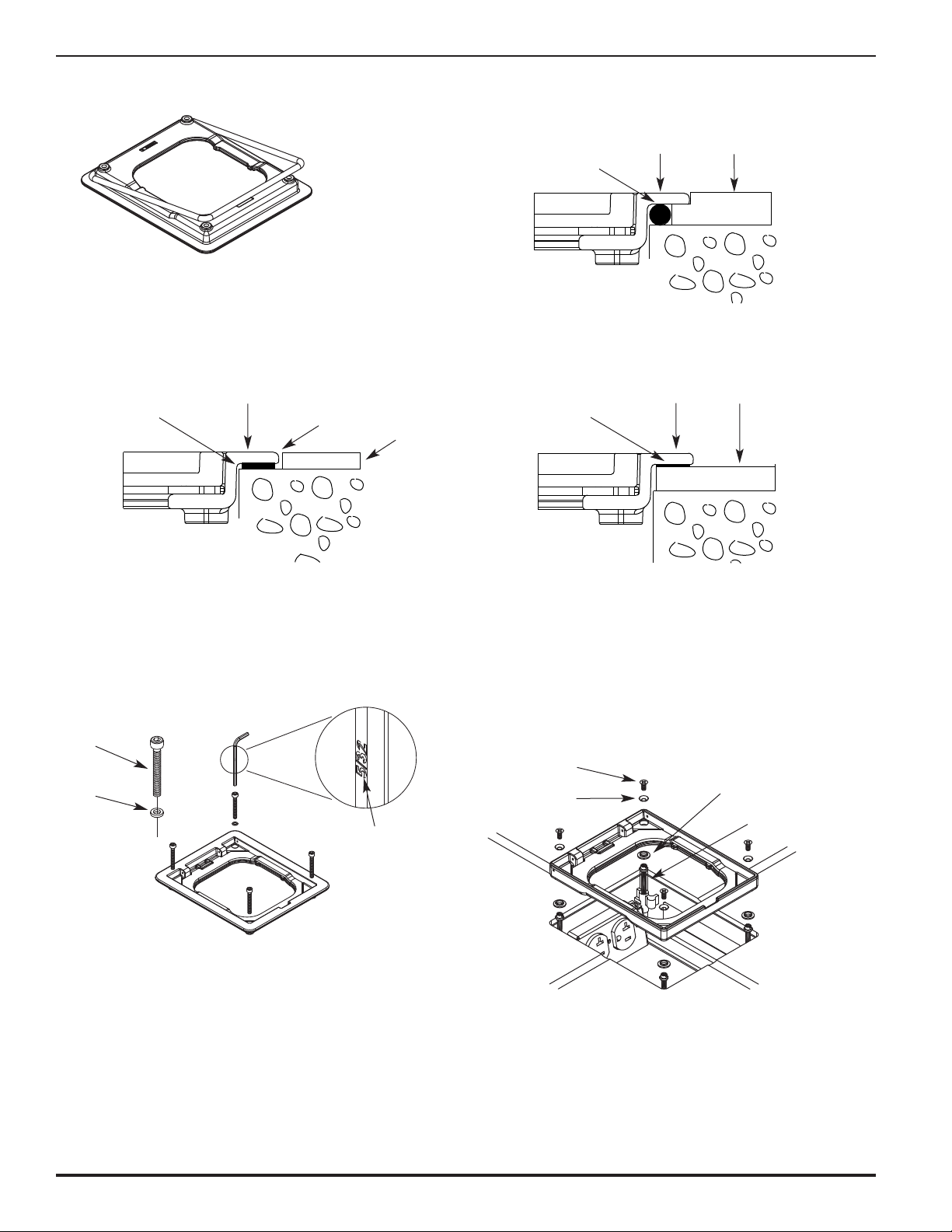
2. INSTALLING GASKET (All Flanged): Place
asket onto the underside of the Trim Ring.
G
2a. Flanged Carpet Installation: Installation view of
ound Gasket and Carpet.
r
2b.Flanged Tile Installation – FLUSH: Place flat Gasket
under Trim Ring prior to positioning on Concrete.
G
lat
F
asket
Flange
Apply Grout or
Silicone Compound
at Joint
ile (1/8"
T
3.2mm])
[
Round
Gasket
Flange
C
arpet
2c. Flanged Tile Installation – SURFACE: Place flat Gasket
under Trim Ring prior to positioning over Tile.
lange
Flat
Gasket
F
Tile
3. ATTACHING THE COVER (Flanged): Slide sealing
Washer over Attachment Screw and mount Flange
to Fitting.
Attachment
Screw (4X)
Sealing
Washer
5/32
4a. ATTACHING THE COVER (Flangeless): Thread adjusting
screws into preset or floor box and place nylon shoulder
washers on screws. Position flange on top and use a slotted
screwdriver to adjust flange elevation flush with floor surface.
#8 Hold-Down
Screw
Beveled
Washer
Nylon Shoulder
Washer
Slotted Adjusting
Screw
2
Page 3
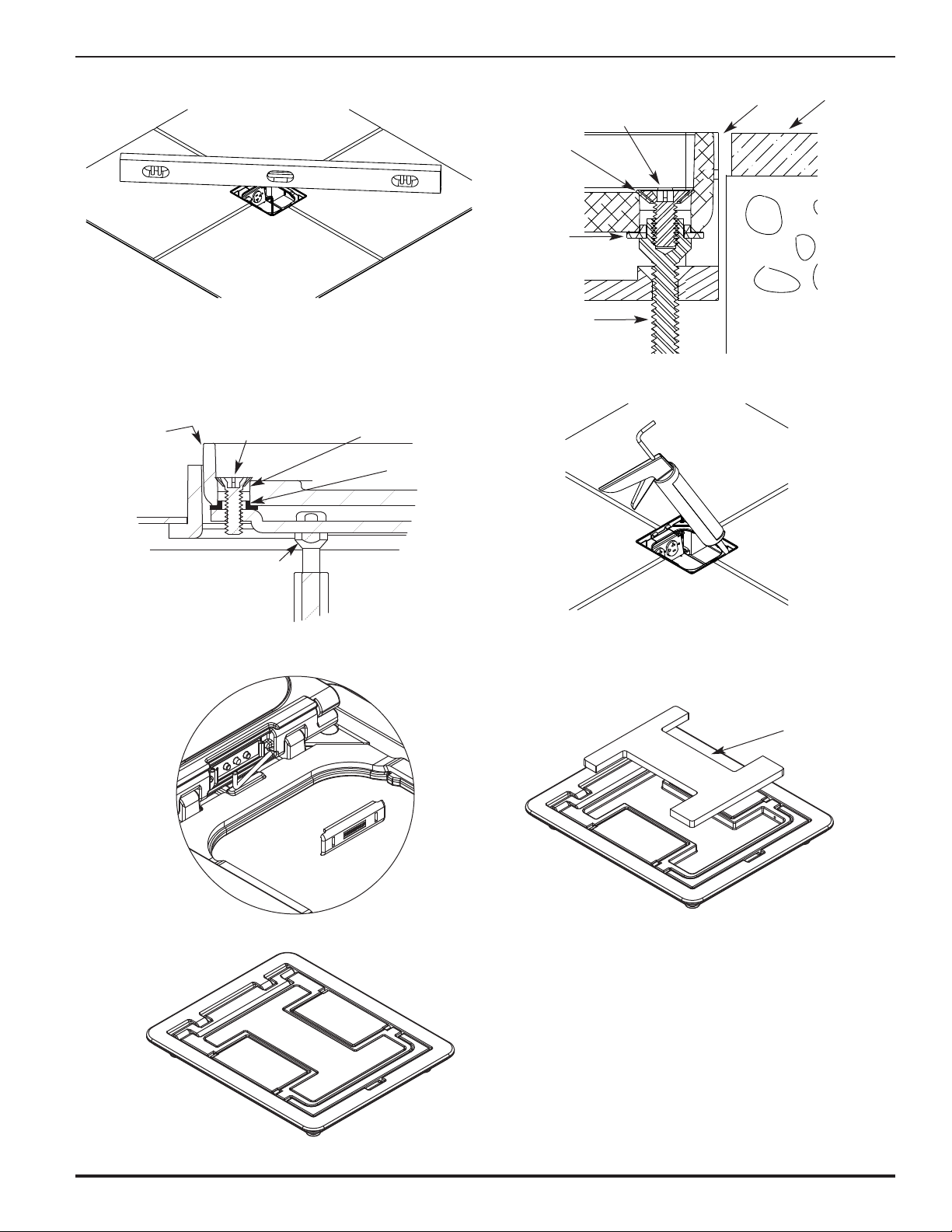
ith Level or Straight Edge.
w
4c. Top of Flange adjusted flush with Floor Covering. 4b.Confirm top edge of Flange is level with Floor Covering
Tile
ylon
N
houlder
S
asher
W
eveled
B
asher
W
A
djusting
crew
S
Hold-Down
Screw
Trim Ring
4d.RFB6 Installation Only – Top of Flange adjusted
flush with Floor Covering.
NON-FLANGED
STYLE FLOOR PORT
TRIM RING
ATTACHMENT
CREW
S
ADJUSTING
SCREW
BEVELED
WASHER
NYLON
SHOULDER
WASHER
5. Re-attach Lid in Trim Ring and re-insert “L” Pins and
Hinge Clip Cap.
4e. Seal edge of Flange with Grout or Silicone.
6. FINISHING (Carpet Installation – FPC Series): Cut
Carpet Insert (see Template on last page) and mount
to Lid with Carpet Tape or Glue.
Carpet
Insert
7. Installation complete.
3
Page 4

FURNITURE FEED BARRIER KIT – Cat. No. PKKIT
For use on Walkercell & Walkerdeck PK Presets
1. Install power and communication Bend Radius
Grommets as shown. Walkerdeck Presets must
2. Install Barrier Base to Preset Receptacle Mounts as shown
using #10-24 Screws.
have Insulation Blanket inserted on deck surface
o maintain Fire Classification.
t
Communication Bend
Radius Grommet
Power
Grommet
PK Preset
Interior
nsulation
I
lanket
B
FURNITURE FEED BARRIER KIT – Cat. No. RFBKIT
For use on RFB4, RFB4-SS, RFB2, RFB2-SS & RFB2-OG Floor Boxes
1. Install Barrier Base to RFB4 Floor Box Receptacle
Mounts as shown using #10-24 Screws.
2. Install Barrier Base to RFB4-SS or RFB2 Series Floor Box
as shown using Screws provided in Base Plate. Follow
directions on next page to complete installation.
ount Barrier Ears to
M
eceptacle Mounts
R
Mount Barrier Ears to
Receptacle Mounts
RFB4
Interior
FURNITURE FEED BARRIER KIT – Cat. No. RFBCIKIT
For use on RFB4-CI Floor Boxes
1. Install Barrier Base to RFB4-CI Floor Box as shown
using Screws provided in Base Plate.
Mount Barrier Ears at
bottom of Floor Box
RFB4-SS &
RFB2 Series
Interior
Mount Barrier Ears at
bottom of Floor Box
RFB4-CI
Interior
4
Page 5

URNITURE FEED BARRIER KIT – Cat. No. NRGKIT
F
For use with UL Listed KAM Industries LTD, dba Cordeck Cellular Metal Raceway Fittings, catalog number
B or N-R-G Bloc
N
1. Insert lower lip of Grommet into the
communication opening of the Cell.
Push the top of the Grommet inward
until it snaps into the Cell opening.
ommunication Bend
C
adius Grommet
R
-R-G Bloc
N
nterior
I
®
V Series Presets
I
2. Install Barrier Base to N-R-G Deck
as shown using #10-32 Screws.
Follow directions below to
omplete installation.
c
ount Barrier
M
ar at bottom
E
3. Install Cell Closure Plate to N-R-G
Deck as shown using #10-32 Screws.
#10-32 x 5/16" Self
Tap (Phillips Drive)
ell Closure
C
late
P
FURNITURE FEED ACTIVATIONS – FPFF SERIES
1. Select suitable Upper Partition height for concrete
pour depth and position over Lower Partition. Attach
Trim Ring. Mount Upper Partition to Trim Ring with
#8-32 x 1/4 FHMS. Fasten Upper and Lower Partitions
with #8-32 x 3/8 PHMS.
#8-32 x 1/4 FHMS
Trim Ring
2. Place Gasket on Flange and remove necessary
Screw Plugs for intended Conduit Fitting.
#8-32 x 7/8"
FHMS (6X)
Power Plate with
1" Trade Size
NPT Opening
NPT Screw Plug
1 1/4" Trade Size
NPT Screw Plug
1 1/4" x 2" Trade Size
1" Trade Size
NPT Reducer
Upper Partition
Bracket
#8-32 x 1/4 PHMS
Lower Partition
Bracket
FLOORPORT BRACKET COMPATIBILITY
These fittings are for indoor installation on carpet or tile
covered concrete floors that contain a cellular raceway
system that has a minimum of 2-1/2" [64 mm] of concrete
topping over the top of the deck. A typical UL Filer
Classified floor activation will consist of the following
components:
PK Series Preset Inserts
“( )” Maximum Quantity of Units Allowed Inside of Preset Insert
COVER ACTIVATION BARRIER COMMUNICATION
ASSEMBLY ASSEMBLY ASSEMBLY BRACKET
FPBTC
FPCTC (1) WPACR — (2) DTB-2
FPBT
FPCT
FPFFTC — (1) PKKIT (1) DTB-2FP
FPFFT
Trim Ring
Communication Plate
with 2" Trade Size NPT
opening (not listed for
power applications)
Gasket
N-R-G-Bloc®Series Preset Inserts
“( )” Maximum Quantity of Units Allowed Inside of Preset Insert
COVER ACTIVATION BARRIER COMMUNICATION
ASSEMBLY ASSEMBLY ASSEMBLY BRACKET
(1) NPACR — (2) DTB-N3
(2) DTB-N3 or
(1) NPACR-SGL — (1) NRGRT8 or
(1) NRGACT12 or
FPBTC (1) NRGACT8 or
FPCTC (1) NPACR-DD — (1) NRGRT8 or
FPBT (1) NPACR-VDD — (1) NRGACT8 or
FPCT (1) NRGRT8 or
(2) NPACR-VDD — —
FPFFTC (1) NRGACT8 or
FPFFT (1) NRGRT8 or
— (1) NRGKIT (1) NRGACT12 or
(1) NRGACT8 or
(1) NRGRT12
(1) NRGACT12 or
(1) NRGRT12
(1) NRGACT12 or
(1) NRGRT12
(1) NRGRT12
5
Page 6

URNITURE FEED ACTIVATIONS – FPFF SERIES
F
(continued)
3. Attach Fitting and Conduit to Cover Plate. Pull wire &
ables and mount Cover Plate to Trim Ring.
c
Thread Conduit
Fitting into Plate
eep Screw Plug
K
or abandonment
f
lexible
F
onduit
C
CAUTION: Tighten Mounting Plate Screws securely
to maintain system ground continuity.
ABANDONMENT
1. Cat. No. S3AXBP
For abandonment, remove Cover Assembly and install
1/4" [6.4mm] Steel Plate using four Leveling Screws
provided. Top of Plate should be flush with finished Floor.
Apply a bead of silicone caulking around the Bottom
Plate to prevent any water or debris entry.
4. Installation complete.
2. Place 1/8" [3.2mm] aluminum Top Plate over the
Bottom Plate. Install the four Screws provided to
secure the two Plates.
PERMANENT ABANDONMENT
1. Cat. Nos. PKCAP & NRGCAP
For permanent abandonment, remove Cover Assembly
and replace with Mud Cap. Repair the Floor Opening
using a suitable Grout or Concrete fill.
6
Page 7

To maintain UL Classification on cellular deck applications, refer to the tables below for maximum quantity of conductors allowed
to exit activation covers. Refer to the UL Fire Resistance Directory for additional floor design information. Depth of concrete over
top of steel deck must be a minimum of 2 1/2" [64 mm]
CABLE CAPACITY FOR CAT. NO. SERIES PK PRESETS
MANUFACTURED BY WALKER SYSTEMS, INC.
COVER CAT. NO. PRESET USED WITH: POWER COMM
FPBTC 2 Duplex Receptacles 4 (a) 64 (c)
FPCTC 2 Duplex Receptacles 4 (a) 64 (c)
FPFFTC Conduit Feed - Power Only 14 (b) 0
FLANGED
FLANGELESS
FLANGED
FLANGELESS
FPFFTC Conduit Feed - Comm. Only 0 224 (d)(e)
FPFFTC Conduit Feed - Power & Comm. 14 (b) 224 (d)(e)
FPBT 2 Duplex Receptacles 4 (a) 64 (c)
FPCT 2 Duplex Receptacles 4 (a) 64 (c)
FPFFT Conduit Feed - Power Only 14 (b) 0
FPFFT Conduit Feed - Comm. Only 0 224 (d)(e)
FPFFT Conduit Feed - Power & Comm. 14 (b) 224 (d)(e)
CABLE CAPACITY FOR CAT. NO. SERIES NB OR NRG BLOC IV PRESETS
COVER CAT. NO. PRESET USED WITH: POWER COMM
FPBTC 2 Duplex Receptacles 4 (a) 96 (c)
FPBTC 4 Duplex Receptacles 8 (a) 64 (c)
FPCTC 2 Duplex Receptacles 4 (a) 96 (c)
FPCTC 4 Duplex Receptacles 8 (a) 64 (c)
FPFFTC Conduit Feed - Power Only 14 (b) 0
FPFFTC Conduit Feed - Comm. Only 0 224 (d)(e)
FPFFTC Conduit Feed - Power & Comm. 14 (b) 224 (d)(e)
FPBTC 2 Duplex Receptacles 4 (a) 96 (c)
FPBTC 4 Duplex Receptacles 8 (a) 64 (c)
FPCTC 2 Duplex Receptacles 4 (a) 96 (c)
FPCTC 4 Duplex Receptacles 8 (a) 64 (c)
FPFFT Conduit Feed - Power Only 14 (b) 0
FPFFT Conduit Feed - Comm. Only 0 224 (d)(e)
FPFFT Conduit Feed - Power & Comm. 14 (b) 224 (d)(e)
NOTES:
(a) Maximum quantity of three-conductor
power supply cords (3/8" [9.5mm]
maximum diameter).
(b) Maximum quantity of No. 12 AWG
conductors allowed when a 1/2" through
1" trade size liquid tight steel conduit with
cast steel 90º elbow is connected to
access cover. When conductors larger
than No. 12 AWG are used, the aggregate
cross-sectional area of the copper
conductors shall not exceed the aggregate
cross-sectional area of
No. 12 AWG conductors.
(c) Maximum quantity of No. 24 AWG
conductors (4-pair communication
cable has eight conductors; 25-pair
communication cable has 50 conductors).
When conductors larger than No. 24
AWG are used, the aggregate crosssectional area of the copper conductors
shall not exceed the aggregate crosssectional area of No. 24 AWG conductors.
Maximum size of any communication
cable is not to exceed 25-pair (3/8"
[9.5mm] maximum diameter).
(d) Maximum quantity of No. 24 AWG
conductors (4-pair communication
cable has eight conductors; 25-pair
communication cable has 50 conductors)
allowed when a 1/2" through 1- 1/4"
trade size liquid tight conduit with cast
steel 90º elbow is connected to access
cover. When conductors larger than
No. 24 AWG are used, the aggregate
cross-sectional area of the copper
conductors shall not exceed the aggregate
cross-sectional area of No. 24 AWG
conductors. Maximum size of any
communication cable is not to exceed
25-pair (3/8" [9.5mm] maximum diameter).
(e) Where local codes permit, conduit
may be omitted when used for
communication type cables. A steel
conduit fitting or a nipple that extends
a minimum distance of 1" [25.4 mm]
beyond surface of cover assembly must
be utilized. Protect wires from damage by
installing a bushing suitable for use with
the type of fitting used. The diameter of
the conduit fitting opening for the passage
of cables shall be no more than 1/8 in.
larger than the diameter of the cable.
Use a suitable fire-resistive caulking such
as 3M Part No. CP 25WB to seal openings
around cables larger than 1/8 in.
7
Page 8

ARPET INSERT TEMPLATE
C
31/32"
[24.8mm]
7/8"
4
124mm]
[
5/16"
3
[84mm]
9/32"
1
33mm]
[
4 1/8"
[105mm]
19/32"
1
40mm]
[
9/32"
1
33mm]
[
19/32"
[14.7mm]
Radius 3/32"
[2.5mm]
© Copyright 2011 Legrand/Wiremold All Rights Reserved
CAUTION: When printing copies of this template,
please be sure template is scaled correctly
and is the correct size once it is printed.
Wiremold
U.S. and International:
60 Woodlawn Street • West Hartford, CT 06110
1-800-621-0049 • FAX 860-232-2062 • Outside U.S.: 860-233-6251
Canada:
570 Applewood Crescent • Vaughan, Ontario L4K 4B4
1-800-723-5175 • FAX 905-738-9721
1 008 150 R2 0411
 Loading...