

Page 1
CS Series
360° PIR Occupancy Sensor
Specifications
Voltages . . . . . . . . . . . . . . . . . . . . .20–30VDC (24VDC Typical)
Current Consumption . . . . . . . . . . .@24VDC, 11mA Maximum
Time Adjustment . . . . . . . . . . . . . . . . .15 seconds–30 minutes
Sensitivity Adjustment . . . . . . . . . . . . . . .Minimum/Maximum
Installation Instructions
U.S. Patents:
4,757,204 • 4,787,722
Des360,842
Syracuse, NY 13221
800.223.4185
Page 2
DESCRIPTION
8 ft
12 ft 12 ft 3 ft 3 ft5 ft 5 ft7 ft 7 ft9 ft 9 ft
0
Typical
desk-top
level
24 ft
44 ft
8 ft
22 ft 13 ft 7 ft 3 ft 0 3 ft 7 ft 13 ft 22 ft
Typical
desk-top
level
The CS Series sensor is a 24VDC Passive Infrared (PIR) occupancy sensor
which controls lighting or HVAC systems based on occupancy in a given area.
PIR sensing systems are passive systems which react to changes in infrared
energy (moving body heat) within the coverage area. PIR sensors must
directly “see” motion of an occupant to detect them, so careful consideration
must be given to sensor placement.
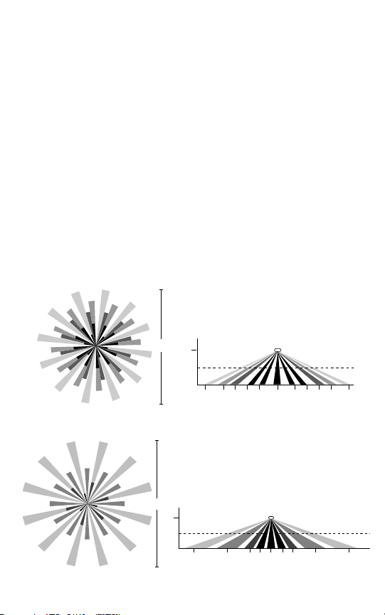
COVERAGE PATTERNS
The CS sensor has a multi-cell, multi-tier Fresnel lens with a field of view
of 360°. The sensor has two lens pattern options. The Extended Range Lens
will cover up to 1200 sq ft and 22 feet from the sensor when mounted at
8 feet. The High Density/Reduced Range Lens will cover up to 500 sq ft and
12 feet from the sensor when mounted at 8 feet.
Coverage shown in the diagrams below is maximum and represents
coverage for half-step, walking motion, with no barriers or obstacles.
DRAWING NOT TO SCALE
High Density/Reduced Range Lens
CS500
Visit our website at www.passandseymour.com
Extended Range Lens (Standard)
CS1200
Page 3
PLACEMENT
CS Sensor
36'
36'
12'
18'
CS Sensor
The effective coverage distances may be slightly less than the maximum
sensing distance (see Coverage Patterns), depending upon obstacles such as
furniture or partitions, and this must be considered when planning the
number of sensors and their positioning. See the list below for approximate
coverage distances for different types of motion.
Approximate coverage, for a mounting height of 8 feet:
Lens option Walking motion Workstation (hand motion)
High Density up to 12 ft radius (500 sq ft) 9 ft radius (300 sq ft)
Extended Range up to 22 ft radius (1200 sq ft) 12 ft radius (500 sq ft)
The CS sensor can be mounted at various heights. When mounting at
heights other than 8 feet, be aware that as you decrease the mounting
height, you will decrease the range and increase the sensitivity to smaller
motions. Conversely, when you increase the height, you will increase the
range and decrease the sensitivity to smaller motions. At heights of more
than 12-14 feet, you may start to significantly reduce sensitivity.
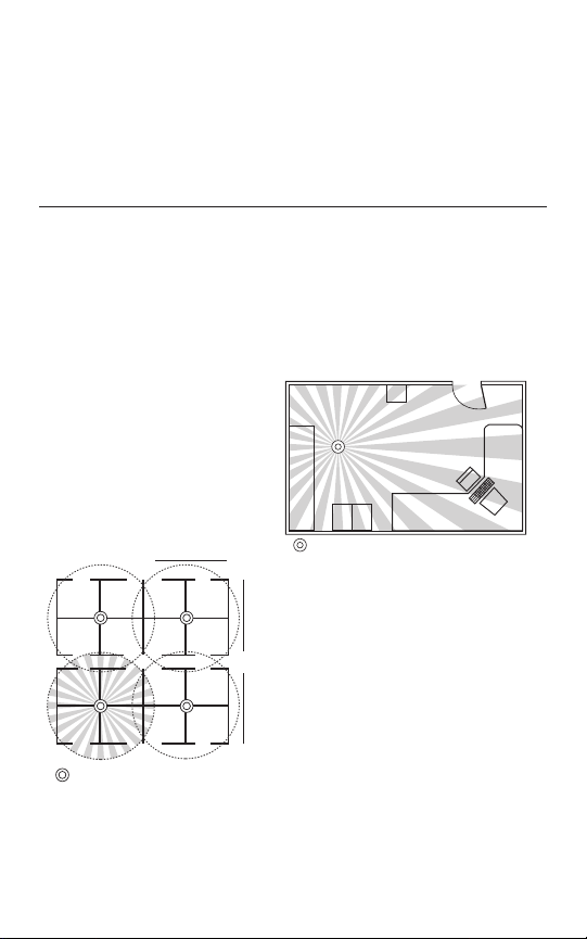
Often the best location to install
a CS sensor in a closed office is
off-center (see fig.1). Avoid placing
a sensor directly in line with an
open door in which it has a clear
view out, as the sensor may detect
people walking by. For open office
areas with partitions it is best to
place sensors over intersections
of four workstations (see fig. 2).
fig.1
Also avoid placing the sensors close to
air ducts, as rapid air currents or the
differences in temperatures may cause
false activations. For large areas of
coverage use multiple sensors.
fig. 2
Call 800.223.4185 for Technical Support
Page 4

INSTALLATION
CAUTION
TURN POWER OFF AT CIRCUIT BREAKER BEFORE INSTALLING SENSOR
A 4-S junction box can be used with a 3" mud-ring when local building codes
mandate that low voltage connections be contained in a junction box.
Otherwise a 3" mud-ring or the provided ceiling attachment ring can be used.
IMPORTANT: If the lens will be masked, the junction box or mud-ring may
need to be positioned so that the mask is oriented properly when the sensor
is installed (see Masking).
Cut a hole in the ceiling tile—if using a:
• Ceiling attachment ring (provided)—cut about 2-3/4" to 3" in diameter.
• 3" mud-ring—cut the hole to accommodate.
To assemble the sensor:
1. If using the ceiling attachment ring, bend the securing straps up so the
sensor housing can be inserted, and attach it to the sensor with the
provided screws.
2. Attach the mask, if using, into the lens recess and onto the securing pins
of the cover.
3. Attach the cover to the rear housing—align tabs on inside of cover to
notches on outside perimeter of rear housing, place cover on sensor, and
twist clockwise to lock.
4. Insert the assembled sensor into the ceiling hole, and if using the mask,
turn the sensor so that the unmasked part of the lens is toward and
centered on the area to be covered.
5. Bend the ceiling attachment ring straps behind the hole to secure (or
attach sensor to mud-ring with screws).
Visit our website at www.passandseymour.com
Page 5

MASKING
White (Neutral)
Red (Load)
Red (Line)White
Black
Hot
N
POWER PACK
Red
Black
Blue
Switch
Control Output 24VDC BLUE
Wires
+24VDC RED
Common BLACK
CS Series
Sensor
Lighting
Load
An insert (mask) is supplied to allow elimination of coverage in unwanted
areas.
The mask is cut as needed and mounted onto anchor pins in the sensor’s
cover.
IMPORTANT: Do not use the mask if full coverage is desired.
IMPORTANT: Before securing the sensor in the mounting location, the
assembled sensor must be turned so the unmasked portion of the lens
faces the coverage area (the blue masked area is visible through the lens).
IMPORTANT: For an already installed sensor—If the sensor can NOT be
turned, then the mask must be cut so that when installed it will be oriented
correctly (note the location of the securing pins in the cover and note that
the cover turns as it locks into position).
Note: At the edges of the masking, there is a small area of reduced
sensitivity, illustrated as the lighter area in the examples below.
Mask
Cut mask into sections
for desired coverage,
shown right.
Reduced sensitivityCoverage area
WIRING DIRECTIONS
CAUTION
TURN POWER OFF AT CIRCUIT BREAKER BEFORE WIRING SENSOR
Pass & Seymour PWP2 series power packs supply power for up to 10
CS Sensors.
When using more sensors than this, multiple power packs are required.
To connect the low voltage wires from the power pack to the sensor:
• RED wire on sensor to RED wire (+24VDC) on power pack.
• BLACK wire (Common) on sensor to BLACK wire on power pack.
• BLUE wire (Control Output) on sensor to BLUE wire on power pack.
Call 800.223.4185 for Technical Support
Page 6

SENSOR ADJUSTMENT
LED
D
IP Switch Control
f
or Time Delay and
S
ensitivity
DIP Switch #
15 seconds
4 minutes
6 minutes
8 minutes
10 minutes
12 minutes
14 minutes
16 minutes
18 minutes
20 minutes
22 minutes
24 minutes
26 minutes
28 minutes
2 minutes
Minimum
Medium Low
Medium High
Maximum
1234 78
SensitivitySensitivity
56
30 minutes
= ON
– = OFF
= Factory Presets
The sensor comes factory preset and ready for operation.
If testing of operation is desired:
• Remove the sensor’s cover (twist).
• Refer to the DIP switch settings chart below for switch configurations.
• Make sure that office furniture and fixtures are in place.
1. Restore power to the lighting circuits and turn the lights on.
• There is a one minute warm-up when power is initially restored to the
sensor before the sensor works properly.
2. Set Time Delay to minimum: DIP switches #1 through 6 set to ON
(15 secs.).
3. Set Sensitivity to maximum: DIP switches
#7 and #8 to ON.
4. Replace the sensor’s cover.
5. Move away from sensor and be still.
The lights should go off after 15 seconds.
Note: If lights remain on, move farther away or out of sight of the sensor.
If lights still remain on, set the Sensitivity to medium high by setting DIP
switches #7 to ON and #8 to OFF, or see Unwanted Sensor Activations
under Troubleshooting.
6. Set the appropriate Time Delay (DIP switches #1 through 6).
The factory preset Time Delay is 18 minutes; other suggestions are:
Offices and conference rooms: 10 minutes.
Classrooms: 10 minutes.
Warehouses: 6 minutes.
Hallways: 4 minutes.
DIP SWITCH SETTINGS
Page 7

TROUBLESHOOTING
CAUTION
USE PROPER SAFETY PRECAUTIONS WHEN
Lights will not turn on:
1. Verify the lens is not masked in the direction being tested (see Masking).
2. Adjust Sensitivity settings up if needed (DIP switches #7 & 8).
3. Verify power pack and sensor connections are correct and secure.
4. Check for +24VDC at RED wire from the power pack to sensor.
• If present, the problem may be with the sensor. Try another sensor (if
available).
• If there is no voltage, see Power Pack High Voltage Checklist, below.
Lights will not turn off:
1. Check that Time Delay settings are correct (DIP switches #1 – 6).
2. Decrease Sensitivity settings if needed (DIP switches #7 & 8).
3. Verify power pack and sensor connections are correct and secure.
4. Disconnect BLUE wire on power pack from sensor.
• If the lights turn off, the problem may be in the sensor. Turn Sensitivity
and Time Delay to minimum and allow the sensor to time-out.
- If the lights turn off, the sensor is working correctly. See Unwanted
• If the lights stay on, the problem may be in the power pack. See Power
Pack High Voltage Checklist, below.
Power Pack High Voltage Checklist:
CAUTION: Use proper high voltage precautions.
1. Check that power pack high voltage wire connections are correct and
secure.
2. Check that the power pack is rated at the correct voltage.
3. Check that there is high voltage going into the power pack.
4. Try another power pack (if available).
Unwanted sensor activations (LED flashes):
Possible causes
1. People moving or walking outside of the desired coverage area, but in
view of the sensor and within it’s range (see Coverage Patterns and
Placement).
2. HVAC vents with heavy air flow.
Possible solutions
1. Masking (see Masking).
2. Setting the Sensitivity lower.
3. Relocating the sensor.
Sensor Override:
If the sensor fails, set DIP switch #6 to OFF. This overrides the sensor and
sets the circuits to “on”.
WORKING WITH OR NEAR HIGH VOLTAGE
Sensor Activations, below. Go through the Sensor Adjustment
process again.
Call 800.223.4185 for Technical Support
Page 8

ORDERING INFORMATION
Catalog# Description
CS500 20–30VDC Occupancy Sensor
CS1200 20–30VDC Occupancy Sensor
PWP2120 Power Pack: 120VAC, 60Hz, 150mA
PWP2277 Power Pack: 277VAC, 60Hz, 150mA, 20A ballast
AR120/277 Slave Pack: 120/277VAC, 60Hz, 20A ballast
Limited FIVE YEAR Warranty
Pass & Seymour/Legrand willremedy any defect in workmanshipor material in Pass &
Seymour/Legrand products whichmay develop underproper and normaluse within five yearsfrom
the date of purchase by a consumer:
(1) by repair or replacement, or, at Pass & Seymour/Legrand’s option, (2)by return of an amount
equal to the consumer’s purchase price. Such remedy is IN LIEU OF ANY AND ALL EXPRESSED
OR IMPLIEDWARRANTIES OF MERCHANTABILITY OR FITNESS FOR A PARTICULAR PURPOSE.
Such remedy by Pass & Seymour/Legrand doesnot include or cover cost of labor forremovalor
reinstallation of the product. ALL OTHER FURTHER ELEMENTSOF DAMAGE (INCIDENTAL OR
CONSEQUENTIALDAMAGES) FOR BREACH OF ANYANDALL EXPRESSED OR IMPLIED
WARRANTIES INCLUDING WARRANTIES OF MERCHANTABILITY OR FITNESS FOR A PARTICULAR
PURPOSE ARE EXCLUDED HEREBY. (Some states do not allow disclaimer or exclusionor limitation
of incidental or consequential damages, so the above disclaimers and limitation or exclusion may
not applyto you.) ANY IMPLIED WARRANTIES INCLUDING WHERE REQUIRED WARRANTIES OF
MERCHANTABILITY OR FITNESS FOR A PARTICULAR PURPOSE SHALL BE LIMITEDTOTHE FIVE
YEAR PERIOD SET FORTH ABOVE. (Some states do not allow limitation on how longan implied
warranty lasts,so theabove limitation may not applyto you.)
Toensure safety, allrepairs toPass & Seymour/Legrand products must be made by Pass &
Seymour/Legrandor under its specific direction. Procedure to obtain performance of any warranty
obligationis as follows:(1) ContactPass & Seymour/Legrand, P.O. Box4822, Syracuse, NY 13221 for
instructions concerning return or repair; (2)return the product to Pass & Seymour/Legrand, postage
paid,with your name and address and a written description of the installationor use of the Pass &
Seymour/Legrandproduct,and the observed defects or failureto operate,or other claimed basis for
dissatisfaction.
This warranty gives you specific legal rights and you may also have other rights which vary from
state to state.
with High Density/Reduced Range Lens
with Extended Range Lens (Standard)
20A ballast/13A incandescent
Technical Support: 800.223.4185 • www.passandseymour.com
P.O. Box 4822, Syracuse, NY 13221-4822
340788 Rev. B 07935
 Loading...