

Page 1

Wiremold electrical systems conform to and should be properly
grounded in compliance with requirements of the current National
Electrical Code or codes administered by local authorities.
All electrical products may present a possible shock or fire
hazard if improperly installed or used. Wiremold electrical products
may bear the mark as UL Listed and/or Classified and
should be installed in conformance with current local and/or the
National Electrical Code.
Convia®Enabled
Walkerflex®System
I N S T A L L A T I O N I N S T R U C T I O N S
Installation Instruction No.: 1 008 478 – August 2009
roducts Covered: NVHUB, LVHUB, NRD1, NRD2, LRD1, LRD2, NPM12, NPM22, NPM24, NPM44, NPM24PF,
P
NPM44PF, CNDU, CLDU, CNWC, CLWC, CNPA, CLPA, CNCS, CLCS, CNCBS, CLCBS, CNCW,
CLCW, CAP3456 & CAP810
NOTE: Label on product indicates which products are suitable for use in air handing spaces
GENERAL INFORMATION
1. Each Convia®Enabled Walkerflex®System connector
2. Disconnect power from source prior to wiring any Walkerflex
3. Installer to determine the maximum power cable length
4. Installer to ensure adequate overload protection based on
5. Refer to appropriate Wiring Diagram and System Key
in accordance with Sec. 300-22(C) of the National Electric Code.
contains a color coded key that indicates rating, conductor
location and orientation. Only like colored keys can be
mated. See Key Configuration and Color Chart on page 11
for available options. Each key is comprised of one or more
configurations.
component into the building’s electrical power system.
based on wire gauge and circuit load.
the system key, rating and circuit load.
Configuration Conductor Location Chart for field connections
of Cat. Nos. CNWC/CLWC (Wire Connector) and
CNCW/CLCW (Cable Whips). Refer to wiring diagram
supplied with CNDU/CLDU (Distribution Unit) for field
termination.
IMPORTANT: Please read all instructions
before beginning.
6. Securing and Supporting of Cables and Components: Refer
to NEC Article 604, Manufacturing Wiring Systems and any
local codes.
7. Cap all unused connector openings with Cat. No. CAP3456
(for 3 through 6 wire system) or Cat. No. CAP810 (for 8 and
10 wire system).
8. All Convia Enabled accessories are available in a 3-6 wire
and 8-10 wire system and are rated 20A, 120V.
9. 277V Convia Enabled Walkerflex components are only
available in 3-6 wire configurations.
10.The Convia Enabled Walkerflex system is compatible with
the standard Walkerflex system of the same configuration
and key.
Page 2
ONVIA ENABLE WALKERFLEX SYSTEM INSTALLATION
C
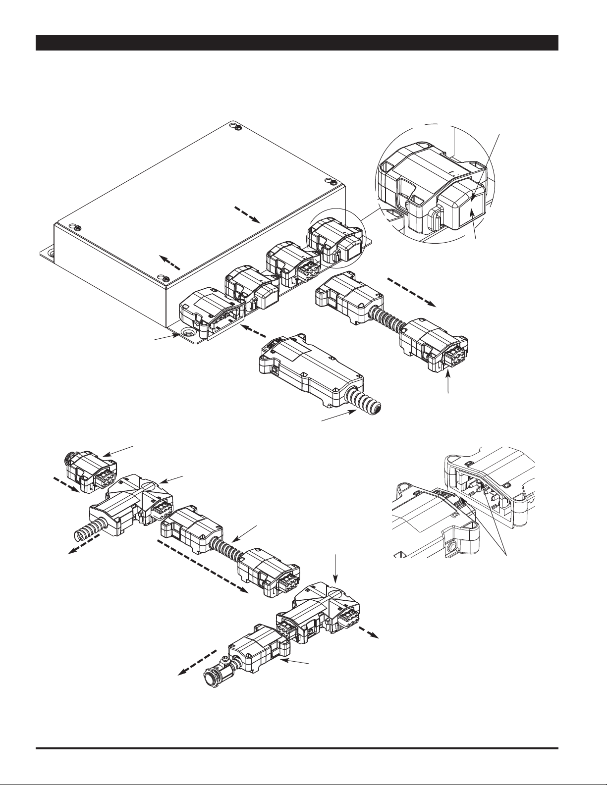
CNDU and CLDU Module & Flex Cables:
The CNDU and CLDU (CLDU is available for 3-6 wire configurations only) module is the main power source and interface to
the Convia Enabled Walkerflex System. It is to be fed from a distribution panel outfitted with appropriate circuit breakers to
rotect wiring.
p
NOTE: Cap Unused Connectors
NDU & CLDU Distribution Unit:
C
P
ow
e
r
O
ut
On All Power Out Modules.
Current Flow
Direction
Pow
e
r
In
Secure Box
in Place
Cat. No. CNWC & CLWC
(Wire Connector)
Cat. No. CNPA & CLPA
(Power Adapter)
Cat. No. CNCS & CLCS
(Cable Set)
F
eed
Pow
Ou
er
t
Connected to
Protected Circuit(s)
Cat. No. CAP3456 End Cap
(for 3-6 wire configurations)
P
ow
e
r
I
n
Cat. No. CAP810 End Cap
(for 8-10 wire configurations)
Pow
er
Ou
t
Cat. No. CNCS &CLCS
(Cable Set)
Current Flow
Direction
Current Flow
Direction
CAUTION: Do not make or break
connections while
circuits are energized.
Current Flow
Direction
Cat. No. CNCBS & CLCBS
(Splitter)
Mate only identical Keys
and Configurations.
Cat. No. CNCW & CLCW
(Cable Whip)
2
Page 3
ONVIA ENABLE WALKERFLEX SYSTEM INSTALLATION
C
(continued)
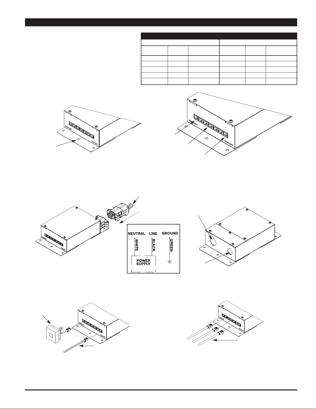
Network Hubs
The Network Hub module makes up the
backbone or Main Bus of the network. Multiple
Network Hubs can be configured to increase the
size of the network or to increase the number of
available ports in an installation location. Up to 50
etwork Hubs can be connected on a single
N
network with a patch cable length of up to 2000
feet. Refer to the ConviaNet Design Guide for
more information.
Step 1: Mount Network Hub securely using
Mounting Holes
Step 2: Connect Power to Network Hub.
appropriate screws and anchors.
For Modular Connection: Connect Convia
Enable Walkerflex Modular Cable
to modular input.
Prewired 5-Port Network Hub
Table A – NETWORK HUB POWER CONFIGURATIONS
120V SYSTEM
Part Walkerflex
umber Phase Configurations
N
VHUBA A 111, 211, 311
N
NVHUBB B 211, 311
VHUBC C 311
N
VHUBD 222
N
NVHUBF Field Wired
J11 Jack for Main
R
us Connections
B
J45 Jacks for Node
R
us Connections
B
RJ11 Jack for Main
Bus Connections
For Field Wired Units: Connect conduit to appropriate
conduit opening and wire per the National Electric
Code. (See Wiring Schematic below or on product
Power input coming
from Distribution Box
or main panel
Current Flow
Direction
label for connections.
3/4" Trade Size
Knockout
277V SYSTEM
art Walkerflex
P
Number Phase Configurations
VHUBA A 111, 211, 311
L
VHUBB B 211, 311
L
LVHUBC C 311
VHUBF Field Wired
L
VHUBF Field Wired
L
Field Wired 5-Port Network Hub
Hub Wiring Schematic
Step 3: Connect Wiremold Convia Enabled pre-terminated
RJ11 cables between the Network Hubs. Install
Communication Loop Closures into RJ11 ports at the
beginning and end of the network run (Main Bus).
Communications Loop
Closure – 2 required
for each network
Wiremold Convia
Enabled Pre-terminated
RJ11 Cable to next
Network Hub in network
NOTE: To ensure proper network functioning, Communication
Loop Closures need to be installed into the beginning
and end of the Main Bus of the network. If there is
only one Network Hub in the installation, then
Communication Loop Closures must be installed in
both RJ11 ports on the Network Hub.
1/2" Trade Size
Knockout
Step 4: Install Wiremold Convia Enabled pre-terminated
RJ45 cables between the Network Hubs and the
Relay Dimmers, Power Modules, Sims, Switches,
and Scene Controllers.
Wiremold Convia Enabled Preterminated RJ45 Cables going
to Relay Dimmers, Power
Modules, Sims, Switches and
Scene Controllers
Step 5: Move on to the installation of Relay Dimmers
and Power Modules.
3
Page 4
CONVIA ENABLE WALKERFLEX SYSTEM INSTALLATION
(continued)
Relay Dimmer
he Relay Dimmer Modules are used to
T
control lighting and other devices, (maximum
20A load) via the Convia Enabled Walkerflex
System. They connect to the Network Hub
to create the Node Bus of the network. Up
to 25 nodes can be connected on a single
Node Bus with a maximum patch cable
length of 1000 feet. Refer to the ConviaNet
Design Guide for more information.
RD1A, NRD2A A 111, 211, 311
N
RD1B, NRD2B B 211, 311
N
NRD1C, NRD2C C 311
NRD1F, NRD2F Field Wired
RD1/LRD1 has one (1) controlled Walkerflex 111 output.
N
NRD2/LRD2 has two (2) controlled Walkerflex 111 outputs.
Table B –RELAY DIMMER POWER CONFIGURATIONS
120V SYSTEM
art Walkerflex
P
Number Phase Configurations
NOTE: For proper dimming function, use only approved dimming ballasts.
Additional ballasts are being added as they become available. For
updated ballast information, visit www.wiremold.com. If a qualified
0-10 VDC dimming ballast is not on the list, please contact your
sales representative for verification.
Step 1: Mount Relay Dimmer securely using
appropriate screws and anchors.
Convia Net
(RJ45) Jack for
Accessory Bus
Connections
Convia Net
(RJ45) for
Mounting Holes
Node Bus
Connections
277V SYSTEM
Part Walkerflex
umber Phase Configurations
N
LRD1A, LRD2A A 111, 211, 311
LRD1B, LRD2B B 211, 311
RD1C, LRD2C C 311
L
RD1F, LRD2F Field Wired
L
APPROVED DIMMING BALLASTS
Manufacturer Name
Advanced Transformer Mark
sram Sylvania Quiktronic
O
niversal Technologies SuperDim
U
General Electric UltraMax
onviaIR (RJ11)
C
ack for IR
J
Connections
Step 2: Connect Power to Relay Dimmers.
For Modular Connection: Connect Convia
Enabled Walkerflex Modular Cable
to modular input and output.
Power input coming
from Distribution Box
or main panel
Current Flow
Direction
Power Output going to
light fixture ballasts
Current Flow
Direction
NRD1 Wiring Schematic
For Field Wired Units: Connect conduit to appropriate
conduit opening and wire per the National
Electric Code. (See Wiring Schematic below
or on product label for connections.
1/2" Trade Size
Knockout
3/4" Trade Size
Knockout
NRD2 Wiring Schematic
4
Page 5

ONVIA ENABLE WALKERFLEX SYSTEM INSTALLATION
C
(continued)
Step 3: Connect Wiremold Convia Enabled Pre-terminated
J45 cables between the Network Hub and the
R
Relay Dimmers to create the Node Bus. The top
ConviaNet RJ45 jack is IN, the bottom ConviaNet
RJ45 jack is OUT.
n from Network
I
ub or upstream
H
elay Dimmer or
R
ower Module
P
Out to downstream
Relay Dimmer or
Power Module
Step 5: Install End Terminators in all ConviaNet RJ45
Node Bus Terminals not being used.
Step 4: Connect Wiremold Convia Enabled Pre-terminated
J45 cables between the Relay Dimmers and the
R
Sims, Sensors, Switches, and Scene Controllers
to create the Accessory Bus. An Accessory Bus
can contain up to 50 devices with a maximum
patch cable length of 500 feet.
Out to Sim, Switch
or Scene Controller
Step 6: Install IR Sensors into ConviaIR RJ11 Port.
R Sensor
I
NOTE: To ensure proper network functioning, End
Terminators need to be installed in all unused
Node ports, and Inline Terminators need to be
installed at the end of all Accessory Bus Runs.
Step 7: Connect Class 2 cable to Dimming Terminal Block.
See Product Label for dimming connections.
0-10VDC Dimmer
Terminal Block
NOTE: Connect appropriate Class 2 cable (Plenum rated
if installed in an Air Handling Space) to terminals
on the Relay Dimmer Modules in accordance with
Article 725 of the National Electric Code.
NOTE: IR Sensor can be installed using a RJ11 In-Line
Connector (PNRJ11LC) and a Wiremold Convia
Enabled pre-terminated RJ11 Cable when
necessary. IR Sensors are needed in all boxes for
commissioning and are recommended to aid in
reconfiguring or troubleshooting network setups.
Step 8: Connect system to light fixtures per the National
Electric Code.
5
Page 6

ONVIA ENABLE WALKERFLEX SYSTEM INSTALLATION
C
(continued)
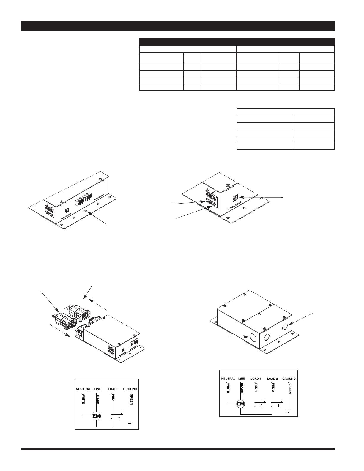
Power Modules
The Power Modules are used to control
general purpose loads, (maximum 20A load)
via the Convia Enabled Walkerflex System.
They connect to the Network Hub to create
the Node Bus of the network. Up to 25
odes can be connected on a single Node
n
Bus with a maximum patch cable length of
1000 feet. Refer to the ConviaNet Design
Guide for more information.
Step 1: Mount Power Modules securely using
appropriate screws and anchors.
Mounting Holes
Table C – POWER MODULE CONFIGURATIONS
art Number of Number of Walkerflex Walkerflex
P
Number Controlled Circuits Total Circuits Input(s) Output(s)
NPM12 12222 222
PM22 22222 222
N
PM12F 12 Field Wired
N
NPM22F 22 Field Wired
NPM24 24422 (2) 222
PM44 44422 (2) 222
N
PM24F 24 Field Wired
N
NPM44F 44 Field Wired
NPM24PF 24422 422
NPM44PF 44422 422
ConviaNet
(RJ45) Jack for
ccessory Bus
A
onnections
C
onviaNet (RJ45)
C
ack for Node
J
us Connections
B
onviaIR (RJ11)
C
ack for IR
J
Connections
Step 2: Connect Power to Power Modules.
For Modular Connection: Connect Convia Enabled Walkerflex Modular
Cable to modular input and output(s).
Two Circuit Power Modules
Pow
er
Out
put
goi
ng t
Pow
f
r
om
or
m
er
i
nput
com
Di
st
r
i
but
ai
n panel
Current Flow
Dire
c
tion
i
ng
i
on Box
Fl
oor
Boxes,
Dev
i
ces,
Cur
Di
r
ect
Pow
from Distribu
or ma
et
c.
r
ent
Fl
i
on
e
r in
in
pa
Poke-
ow
pu
t c
n
e
omin
tion
l
Thr
o
u
Four Circuit Partition Feed Modules
g
Box
Pow
er
i
nput
f
r
om
Di
st
or
m
ai
n panel
Current Flow
Direction
Four Circuit Power Modules
com
i
ng
r
i
but
i
on Box
Cur
r
ent
Fl
Di
Power Output going to
Floor Boxes, Poke-Thru
Devices, etc.
Current Flow
Direction
ow
r
ect
i
on
Pow
Fl
oor
Dev
er
Out
Boxes,
i
ces,
et
put
Poke-
c.
goi
ng t
Thr
o
u
Current Flow
Direction
6
Page 7

ONVIA ENABLE WALKERFLEX SYSTEM INSTALLATION
C
(continued)
Step 2 (continued):
For Field Wired Units: Connect conduit to appropriate conduit opening and wire per the National
Electric Code. (See Wiring Schematic below or on product label for connections).
Four Circuit Power Modules – Field Wired
3
/
4
"
Tr
ade
Si
z
Kn
ockou
e
t
3
Kn
Two Circuit Power Modules – Field Wired
/
4
"
Tr
ade
Si
z
ockou
e
t
NPM12 Wiring Schematic NPM24 Wiring Schematic
NPM22 Wiring Schematic NPM44 Wiring Schematic
1
Kn
/
2
"
ockou
Tr
ade
Si
z
e
t
1
Kn
/
2
"
ockou
Tr
ade
Si
z
e
t
Step 3: Connect Wiremold Convia Enabled pre-terminated
RJ45 cables between the Network Hubs and the
Power Modules to create the Node Bus. The top
ConviaNet RJ45 jack is IN, the bottom ConviaNet
RJ45 jack is OUT.
I
n f
r
om
Net
w
or
upst
m
M
m
odul
r
eam
er
k
or
e
Ou
t to dow
n
s
Dimme
tream
r or
le
Relay
Power Modu
Hub or
Rel
ay
Pow
Di
er
Step 5: Install End Terminators in all ConviaNet RJ45
Node Bus terminals not being used.
NOTE: To ensure proper network functioning, End Terminators
need to be installed in all unused Node ports, and End
Terminators or Inline Terminators need to be installed
at the end of all Accessory Bus Runs.
Step 4: Connect Wiremold Convia Enabled pre-terminated
RJ45 cables between the Power Modules and the
Sims, Switches, and Scene Controllers to create
the Accessory Bus. An Accessory Bus can contain
up to 50 devices with a maximum patch cable
length of 500 feet.
Out
t
o Si
m
,
Sw
i
t
or
Scene Cont
ch
r
ol
l
er
Step 6: Install IR Sensors into ConviaIR RJ11 Port.
IR Sensor
NOTE: IR Sensor can be installed using a RJ11 In-Line
Connector (PNRJ11LC) and a Wiremold Convia Enabled
pre-terminated RJ11 Cable when necessary. IR Sensors
are needed in all boxes for commissioning and are
recommended to aid in reconfiguring or troubleshooting
network setups.
7
Page 8

ALKERFLEX SYSTEM ACCESSORIES
W
TYPICAL PREWIRED ACCESS FLOOR BOX INSTALLATIONS
Access
Floor Box
Cat. No. CNCS
(Cable Set)
Cat. No. CNPA
(Power Adapter)
Cat. No. CNCS
(Cable Set)
CE6STCP222PA
Cat. No. CNCW
(Cable Whip)
CE3ATCAL111PA
CE4ATCAL222PA
CE4FFATCAL422CW
8
Page 9

ALKERFLEX SYSTEM WIRING DIAGRAMS
L1 Black
W
120V 20A SYSTEM FOR 1, 2, 3 OR 4 LINE CONDUCTORS
ONNECTED TO A GROUNDED THREE-PHASE WYE
C
120V 20A SYSTEM FOR 1 OR 2 LINE CONDUCTORS
CONNECTED TO A DUAL NEUTRAL GROUNDED
THREE-PHASE WYE
120V 20A SYSTEM FOR 1 OR 2 LINE CONDUCTORS
ONNECTED TO A DUAL NEUTRAL GROUNDED
C
THREE-PHASE WYE AND ISOLATED GROUND
120V 20A SYSTEM FOR 1 OR 2 LINE CONDUCTORS
CONNECTED TO A GROUNDED THREE-PHASE WYE
AND ISOLATED GROUND
277V 20A SYSTEM FOR 1, 2, OR 3 LINE CONDUCTORS
CONNECTED TO A GROUNDED THREE-PHASE WYE
277V 20A SYSTEM FOR 1 OR 2 LINE CONDUCTORS
CONNECTED TO A DUAL NEUTRAL GROUNDED
THREE-PHASE WYE
277V 20A SYSTEM FOR 1 OR 2 LINE CONDUCTORS
CONNECTED TO A DUAL NEUTRAL GROUNDED
THREE-PHASE WYE AND ISOLATED GROUND
277V 20A SYSTEM FOR 1 OR 2 LINE CONDUCTORS
CONNECTED TO A GROUNDED THREE-PHASE WYE
AND ISOLATED GROUND
9
Page 10

ALKERFLEX SYSTEM WIRING DIAGRAMS
W
(continued)
120V 20A SYSTEM FOR 4 LINE CONDUCTORS & 2
EUTRALS CONNECTED TO AN ISOLATED GROUND
N
THREE-PHASE WYE
120V 20A SYSTEM FOR 3 LINE CONDUCTORS & 3
NEUTRALS CONNECTED TO AN ISOLATED GROUND
THREE-PHASE WYE
120V 20A SYSTEM FOR 6 LINE CONDUCTORS & 2
EUTRALS CONNECTED TO AN ISOLATED GROUND
N
THREE-PHASE WYE
120V 20A SYSTEM FOR 4 LINE CONDUCTORS & 4
NEUTRALS CONNECTED TO AN ISOLATED GROUND
THREE-PHASE WYE
120V 20A SYSTEM FOR 6 LINE CONDUCTORS & 3
NEUTRALS CONNECTED TO A THREE-PHASE WYE
10
Page 11

6
7
8
5
4
3
9
10
2
G
6
7
8
5
4
3
9
10
2
G
6
7
8
5
4
3
9
10
2
G
6
7
8
5
4
3
9
10
2
G
6
7
8
5
4
3
9
10
2
G
6
7
8
5
4
3
9
10
2
G
6
7
8
5
4
3
9
10
2
G
6
7
8
5
4
3
9
10
2
G
6
7
8
5
4
3
9
10
2
G
6
7
8
5
4
3
9
10
2
G
G
5
6
1
2
3
G
5
6
1
2
3
G
5
6
1
2
3
G
5
6
1
2
3
G
5
6
1
2
3
G
5
6
1
2
3
ALKERFLEX SYSTEM WIRING CONFIGURATIONS
W
WALKERFLEX 3-6 KEY CONFIGURATIONS
ERMINAL
T
LOCK
YSTEM COLOR KEY POWER OUT POWER IN
S
20A, 120V Black A
20A, 120V, Orange B
IG
20A, 120V, Clear C
2N
20A, 277V Yellow D
20A, 277V, Green E
IG
20A, 277V, Blue F
2N
B
WALKERFLEX 8-10 KEY CONFIGURATIONS
ERMINAL
T
LOCK
YSTEM COLOR KEY POWER OUT POWER IN
S
20A, Black 422
120V,
4H/2N/IG
20A, Orange 442
120V,
4H/4N/IG
20A, Natural 332
120V,
3H/3N/IG
20A, Blue 631
120V,
6H/3N/G
20A, Ivory 622
120V,
6H/2N/IG
B
8-10 SYSTEM KEYING CONFIGURATIONS & COLORS
TERMINAL
SYSTEM COLOR KEY CONFIG COLOR COLOR COLOR
BLOCK WIRE WIRE WIRE
CONDUCTOR
120V Black 422 422 7 Line 1: Black 2 Neutral 1: White 1 Equip Gnd: Green
4H/2N/IG 8 Line 2: Red 3 Neutral 2: Wht/Red 6 ISO Gnd: Grn/Yel
9 Line 3: Blue
10 Line 4: Blk/Wht
120V Orange 442 442 7 Line 1: Black 2 Neutral 1: White 1 Equip Gnd: Green
4H/4N/IG 8 Line 2: Red 3 Neutral 2: Wht/Red 6 ISO Gnd: Grn/Yel
9 Line 3: Blue 4 Neutral 3: Wht/Blu
10 Line 4: Blk/Wht 5 Neutral 4: Wht/Blk
120V Natural 332 332 7 Line 1: Black 2 Neutral 1: White 1 Equip Gnd: Green
3H/3N/IG 8 Line 2: Red 3 Neutral 2: Wht/Red 6 ISO Gnd: Grn/Yel
9 Line 3: Blue 4 Neutral 3: Wht/Blu
120V Blue 631 631 5 Line 1: Black 2 Neutral 1: White 1 Equip Gnd: Green
6H/3N/G 6 Line 2: Red 3 Neutral 2: Wht/Red
7 Line 3: Blue 4 Neutral 3: Wht/Blu
8 Line 4: Blk/Wht
9 Line 5: Red/Wht
10 Line 6: Blu/Wht
120V Ivory 622 622 4 Line 1: Black 2 Neutral 1: White 1 Equip Gnd: Green
6H/2N/IG 5 Line 2: Red 3 Neutral 2: Wht/Red 6 ISO Gnd: Grn/Yel
7 Line 3: Blue
8 Line 4: Blk/Wht
9 Line 5: Red/Wht
10 Line 6: Blu/Wht
HN G
LOCATION
LOCATION
CONDUCTOR
LOCATION
CONDUCTOR
11
Page 12

ALKERFLEX SYSTEM WIRING CONFIGURATIONS
W
(continued)
3-6 SYSTEM KEYING CONFIGURATIONS & COLORS
TERMINAL
BLOCK WIRE WIRE WIRE
COLOR KEY CONFIG COLOR COLOR COLOR
Black A 111 1 Line 1: Black 6 Neutral 1: White 4 Equip Gnd: Green
211 1 Line 1: Black 6 Neutral 1: White 4 Equip Gnd: Green
311 1 Line 1: Black 6 Neutral 1: White 4 Equip Gnd: Green
411 1 Line 1: Black 6 Neutral 1: White 4 Equip Gnd: Green
Orange B 112 1 Line 1: Black 6 Neutral 1: White 4 Equip Gnd: Green
212 1 Line 1: Black 6 Neutral 1: White 4 Equip Gnd: Green
222 1 Line 1: Black 6 Neutral 1: White 4 Equip Gnd: Green
Clear C 221 1 Line 1: Black 6 Neutral 1: White 4 Equip Gnd: Green
Yellow D 111 1 Line 1: Black 6 Neutral 1: White 4 Equip Gnd: Green
211 1 Line 1: Black 6 Neutral 1: White 4 Equip Gnd: Green
311 1 Line 1: Black 6 Neutral 1: White 4 Equip Gnd: Green
411 1 Line 1: Black 6 Neutral 1: White 4 Equip Gnd: Green
Green E 112 1 Line 1: Black 6 Neutral 1: White 4 Equip Gnd: Green
212 1 Line 1: Black 6 Neutral 1: White 4 Equip Gnd: Green
222 1 Line 1: Black 6 Neutral 1: White 4 Equip Gnd: Green
Blue F 221 1 Line 1: Black 6 Neutral 1: White 4 Equip Gnd: Green
HN G
LOCATION
CONDUCTOR
LOCATION
CONDUCTOR
LOCATION
CONDUCTOR
2 Line 2: Red
2 Line 2: Red
3 Line 3: Blue
2 Line 2: Red
3 Line 3: Blue
5 Line 4: Blk/Wh
5 ISO Gnd: Grn/Yel
2 Line 2: Red 5 ISO Gnd: Grn/Yel
2 Line 2: Red 3 Neutral 2: Wht/Red 5 ISO Gnd: Grn/Yel
2 Line 2: Red 5 Neutral 2: Wht/Red
2 Line 2: Red
2 Line 2: Red
3 Line 3: Blue
2 Line 2: Red
3 Line 3: Blue
5 Line 4: Blk/Wh
5 ISO Gnd: Grn/Yel
2 Line 2: Red 5 ISO Gnd: Grn/Yel
2 Line 2: Red 3 Neutral 2: Wht/Red 5 ISO Gnd: Grn/Yel
2 Line 2: Red 3 Neutral 2: Wht/Red 5
© Copyright 2009 Legrand All Rights Reserved
WIREMOLD
U.S. and International:
60 Woodlawn Street • West Hartford, CT 06110
1-800-621-0049 • FAX 860-232-2062 • Outside U.S.: 860-233-6251
Canada:
570 Applewood Crescent • Vaughan, Ontario L4K 4B4
1-800-723-5175 • FAX 905-738-9721
1 008 478 0809
 Loading...