

Page 1
4 Channel Power over Ethernet
Network Video Recorder
USER MANUAL
1308247 Rev. A
Page 2

301 Fulling Mill Road, Suite G
Middletown, PA 17057
(800) 223-4162
©Copyright 2016 by Legrand,
Inc All Rights Reserved.
www.legrand.us
Page 2
INSTRUCTION MANUAL
To obtain the best performance and ensure device function correctly, please read this instruction manual
carefully and completely.
FCC Compliance
USER-INSTALLER CAUTION:
YOUR AUTHORITY TO OPERATE THIS FCC VERIFIED EQUIPMENT COULD BE VOIDED IF YOU MAKE
CHANGES OR MODIFICATIONS NOT EXPRESSLY APPROVED BY THE PARTY RESPONSIBLE FOR
COMPLIANCE TO PART 15 OF THE FCC RULES.
NOTE:
THIS EQUIPMENT HAS BEEN TESTED AND FOUND TO COMPLY WITH THE LIMITS FOR A CLASS B
DIGITAL DEVICE, PURSUANT TO PART 15 OF THE FCC RULES. THESE LIMITS ARE DESIGNED TO
PROVIDE REASONABLE PROTECTION AGAINST HARMFUL INTERFERENCE WHEN THE EQUIPMENT
IS OPERATED IN A COMMERCIAL ENVIRONMENT. THIS EQUIPMENT GENERATES, USES, AND CAN
RADIATE RADIO FREQUENCY ENERGY AND IF NOT INSTALLED AND USED IN ACCORDANCE WITH
THE INSTRUCTION MANUAL, MAY CAUSE HARMFUL INTERFERENCE TO RADIO COMMUNICATIONS.
OPERATION OF THIS EQUIPMENT IN A RESIDENTIAL AREA IS LIKELY TO CAUSE HARMFUL
INTERFERENCE IN WHICH CASE THE USER WILL BE REQUIRED TO CORRECT THE INTERFERENCE
AT HIS OWN EXPENSE.
THIS CLASS B DIGITAL APPARATUS MEETS ALL REQUIREMENTS OF THE
CANADIAN INTERFERENCE-CAUSING EQUIPMENT REGULATIONS.
Page 3

301 Fulling Mill Road, Suite G
Middletown, PA 17057
(800) 223-4162
©Copyright 2016 by Legrand,
Inc All Rights Reserved.
www.legrand.us
Page 3
WARNINGS, CAUTIONS & COPYRIGHT
The lightning flash with arrowhead symbol, within an equilateral triangle, is intended to alert the user
to the presence of insinuated "dangerous voltage" within the products enclosure that may be of
sufficient magnitude to constitute a risk of electric shock to persons.
The exclamation point within an equilateral rhombus is intended to alert the user to the presence of
important operating and maintenance (servicing) instruction in the literature accompanying the
product.
CAUTION: TO REDUCE THE RISK OF ELECTRIC SHOCK.
DO NOT REMOVE COVER (OR BACK).
NO USER-SERVICEABLE PARTS INSIDE.
REFER SERVICING TO QUALIFIED SERVICE
PERSONNEL.
RISK OF ELECTRIC SHOCK
DO NOT OPEN
CAUTION
WARNING
TO REDUCE THE RISK OF FIRE OR ELECTRIC SHOCK, DO NOT EXPOSE THIS PRODUCT TO RAIN OR MISTURE.
DO NOT INSERT ANY METALLIC OBJECT THROUGH VENTILATION GRILLS.
CAUTION
Explanation of Graphical Symbols
USERS OF THE SYSTEM ARE RESPONSIBLE FOR CHECKING AND COMPLYING WITH ALL FEDERAL, STATE,
AND LOCAL LAWS AND STATUTES COIPCERNING THE MONITORING AND RECORDING OF VIDEO AND AUDIO
SIGNALS. ULTRAK SHALL NOT BE HELD RESPONSIBLE FOR THE USE OF THIS SYSTEM IN VIOLATION OF
CURRENT LAWS AND STATUTES.
COPYRIGHT
THE TRADEMARKS MENTIONED IN THE MANUAL ARE LEGALLY REGISTERED TO THEIR RESPECTIVE
COMPANIES.
Page 4

301 Fulling Mill Road, Suite G
Middletown, PA 17057
(800) 223-4162
©Copyright 2016 by Legrand,
Inc All Rights Reserved.
www.legrand.us
Page 4
TABLE OF CONTENTS
1. Installation ..................................................................................................................... 5
2. Live View ........................................................................................................................ 8
3. Camera ......................................................................................................................... 13
2. Record .......................................................................................................................... 20
3. Alarm............................................................................................................................. 23
4. Network ........................................................................................................................ 25
5. Authority ...................................................................................................................... 32
6. Storage ......................................................................................................................... 34
7. System .......................................................................................................................... 36
8. Player ............................................................................................................................ 40
9. Plugin ............................................................................................................................ 47
10. Log List ........................................................................................................................ 47
Page 5
301 Fulling Mill Road, Suite G
Middletown, PA 17057
(800) 223-4162
©Copyright 2016 by Legrand,
Inc All Rights Reserved.
www.legrand.us
Page 5
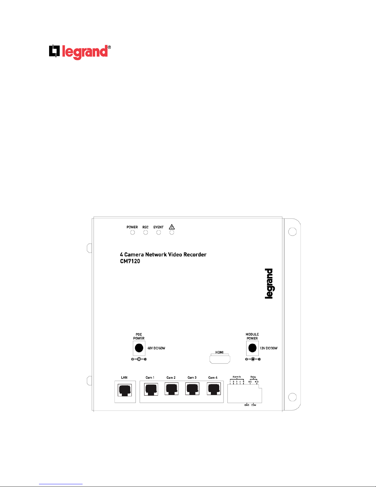
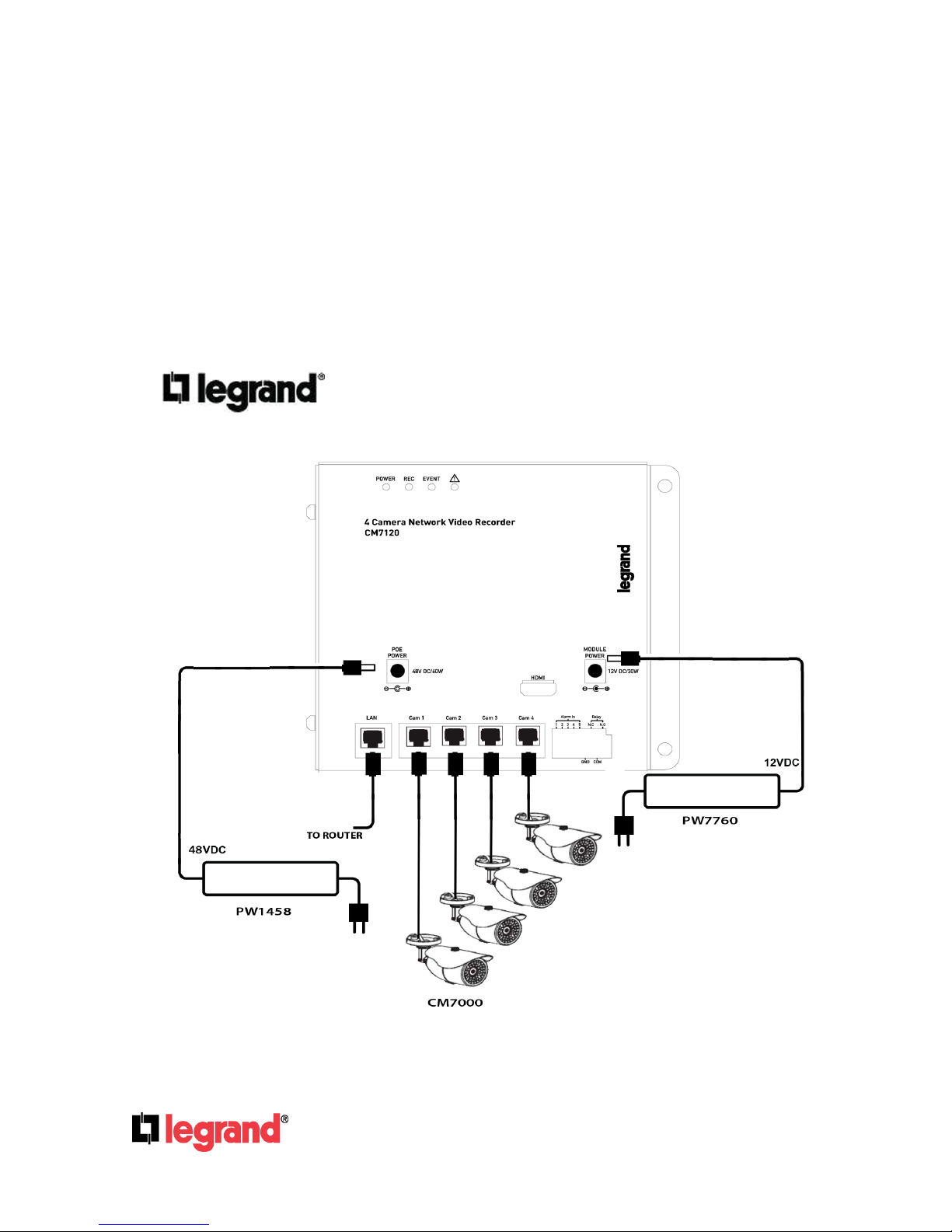
1. Installation
The CM7120 Network Video Recorder will mount into the On-Q structured wiring enclosure.
Once installed, a local network connection will be required to access the CM7120. The
Network Video Recorder features a LAN port specifically for connection to an existing router
or switch. The CM7120 also features four camera ports that support the 802.3af PoE standard
to power any cameras connected to the device.
NOTE: An internet connection is required for remote access of this product
ACCOUNT & PASSWORD LOGIN
Page 6
301 Fulling Mill Road, Suite G
Middletown, PA 17057
(800) 223-4162
©Copyright 2016 by Legrand,
Inc All Rights Reserved.
www.legrand.us
Page 6
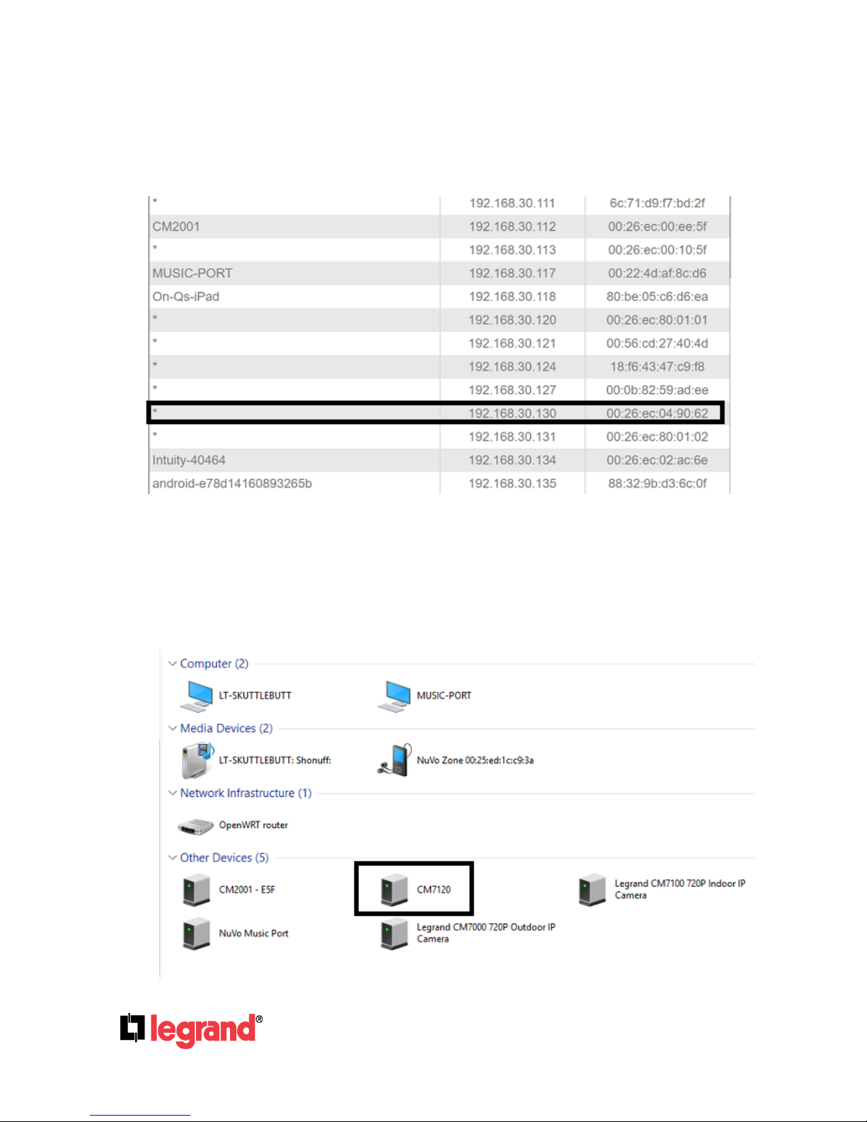
The NVR will automatically pull an IP address from the router it is connected to. The device
will appear in the DHCP client list of the router and can be accessed at the IP address. The
NVR can be identified in the list by its MAC address which will always begin with a 00:26:ec
address.
The NVR will automatically appear under the network list in Windows as well. Open up the
“My Computer” window and on the navigation pane on the left side of the window select
“Network”. A prompt may appear asking to enable network and sharing in Windows. If it has
not already been enabled, it will need to be turned on to properly discover any network
devices. The NVR will appear in this list with its part number. Simply double click the icon to
open the device in the default browser.
Page 7
301 Fulling Mill Road, Suite G
Middletown, PA 17057
(800) 223-4162
©Copyright 2016 by Legrand,
Inc All Rights Reserved.
www.legrand.us
Page 7
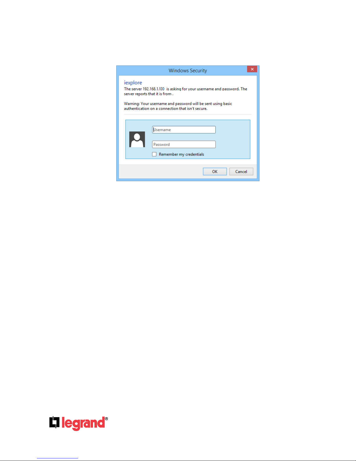
Alternately, type the IP address of the NVR directly into the address bar of the browser. The
following User name & Password Login window will pop up.
Enter Default user name & password: admin/admin
Page 8
301 Fulling Mill Road, Suite G
Middletown, PA 17057
(800) 223-4162
©Copyright 2016 by Legrand,
Inc All Rights Reserved.
www.legrand.us
Page 8
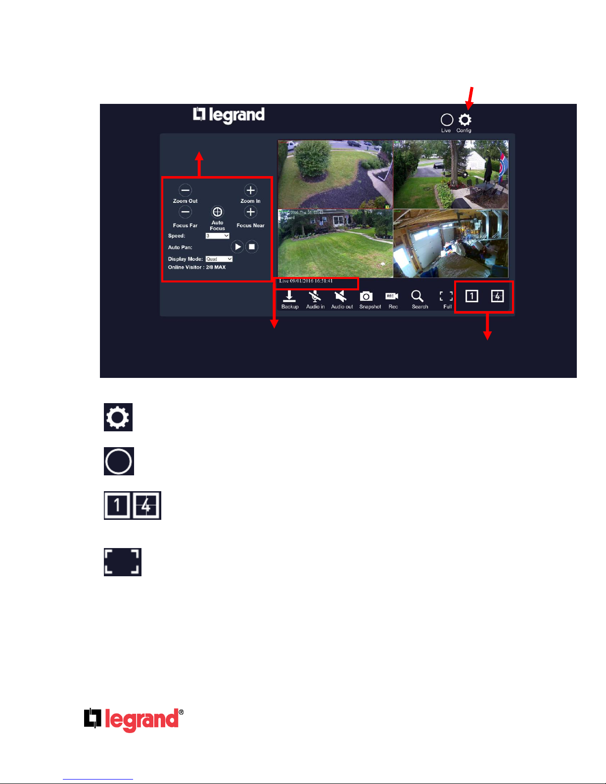
2. Live View
NVR Configuration
Screen Pattern
PTZ Control
System Time
A. Configuration:Get into the NVR setup menu.
B. Live:Click on the icon to return to the Live mode interface from other modes.
C. Screen Pattern:Click on each icon to enter a 1 screen pattern or 1/4 screen
pattern mode. Click on a channel screen twice to view its full image.
D. Full Screen: Click to enter full screen mode. You can still adjust the screen pattern
by clicking on the icons below.
Page 9
301 Fulling Mill Road, Suite G
Middletown, PA 17057
(800) 223-4162
©Copyright 2016 by Legrand,
Inc All Rights Reserved.
www.legrand.us
Page 9
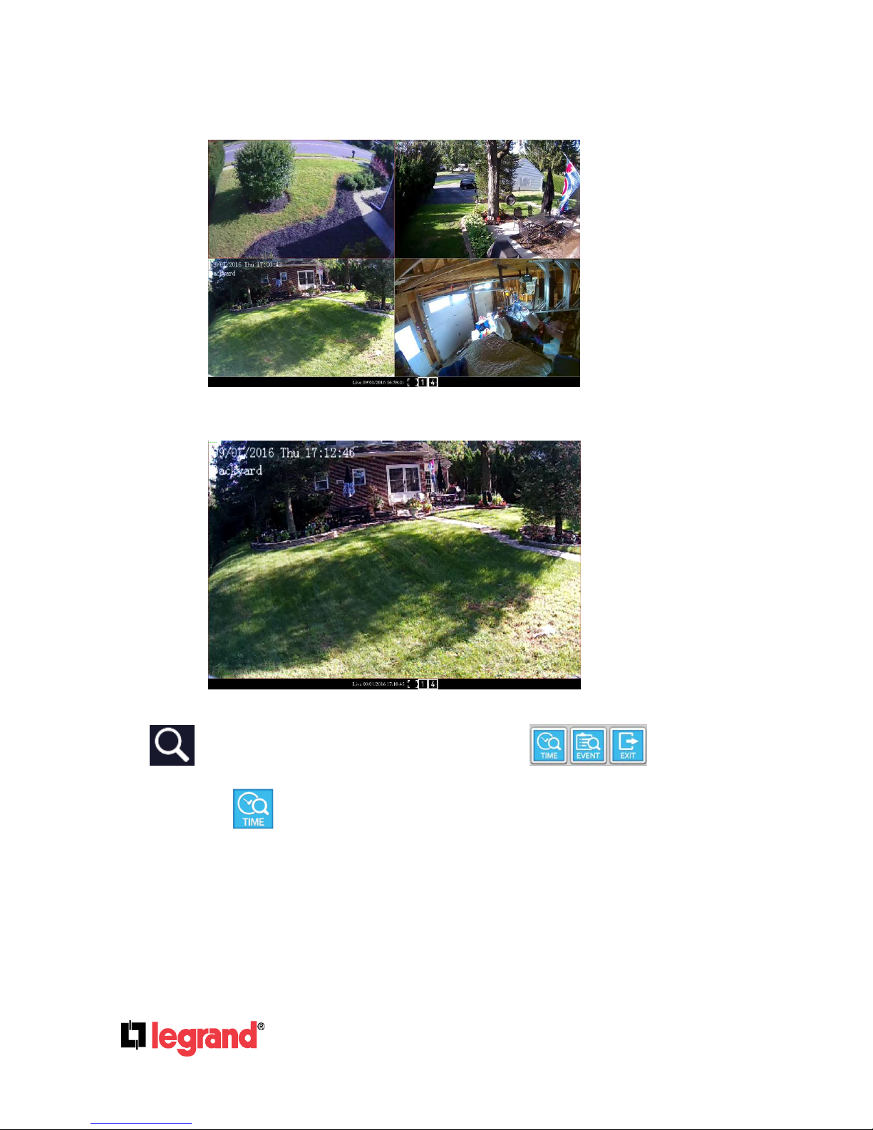
When clicking 4:
When clicking 1:
Press esc button on the PC keyboard to quit this mode.
E. Search:Click to enable Search menu. 3 icons will pop up.
E1. Time Search
Click on the icon to enter Time Search page where you can see the time frame of your
recorded video.
Page 10

301 Fulling Mill Road, Suite G
Middletown, PA 17057
(800) 223-4162
©Copyright 2016 by Legrand,
Inc All Rights Reserved.
www.legrand.us
Page 10
Place the mouse cursor on the time frame of the video that is desired for playback.
Click on Start Play button to continue.
f2. Event Search
After entering the events search page, the user can click on the event log item which
is displayed in a list on the top right to start watching its playback video.
The user can click the Event Type Filter button to enter a list of events and select
specific types to be included for being recorded on the video. Set the time range in
Time Filter and tick any channels for the system to examine in Channel Filter.
f3. Exit: Click to return to live mode.
Page 11
301 Fulling Mill Road, Suite G
Middletown, PA 17057
(800) 223-4162
©Copyright 2016 by Legrand,
Inc All Rights Reserved.
www.legrand.us
Page 11
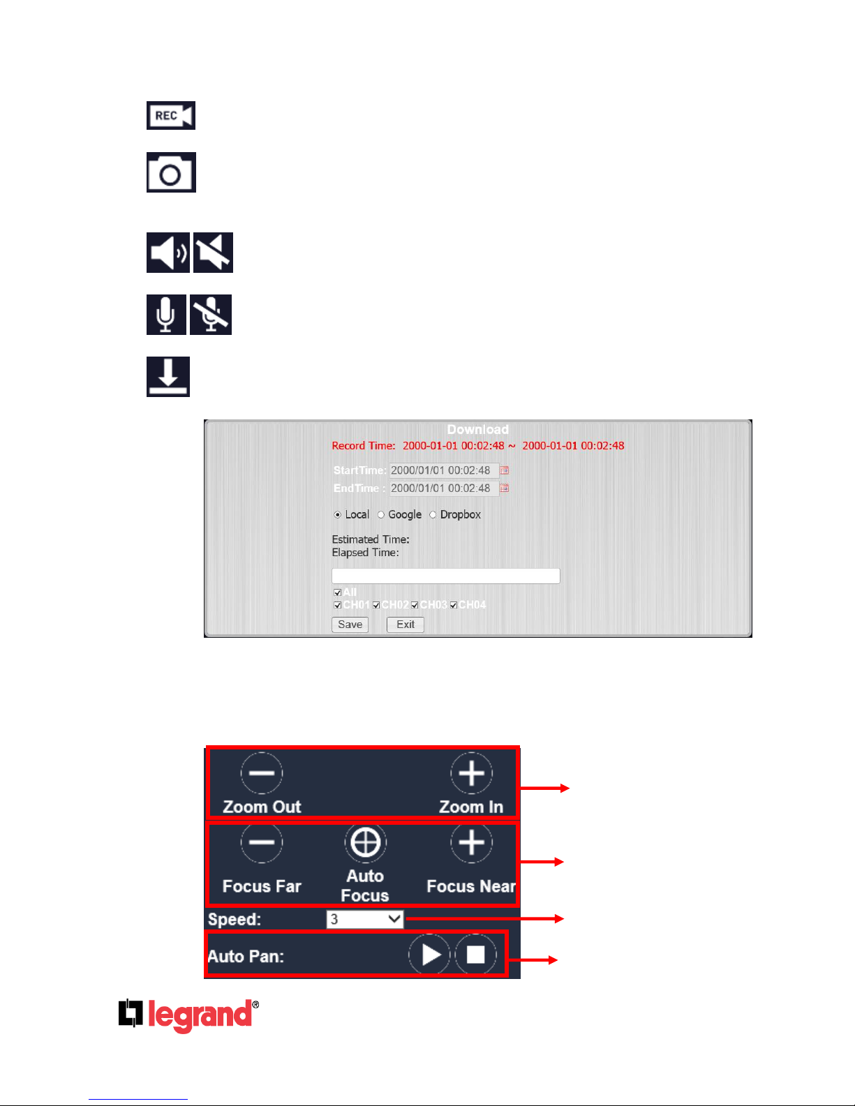
F. Recording:Click to start recording the live video to PC or storage device. A window
PTZ Focus
PTZ Zoom in/out
Preset Point Setup
Auto Pan Function
will pop up on the screen for the user to set up the recorded file saving path.
G. Snapshot:Save a single picture from the image. A window will pop up on the screen
for the user to set up the snapshot file saving path.
H. Audio Out:Click this icon to enable/disable the audio.
I. Audio In:Click the icon to enable or disable the one way audio.
J. Backup:Set up and manage video back-up files.
Set up theStartTime, EndTime, and assign which channel (CH01~CH04) to record
the backup files from. For Backup type, once the storage device or destination is set
ready, click Start to proceed or Stop to cancel.
K. PTZ Control Panel
For PTZ camera settings and controls.
Page 12

301 Fulling Mill Road, Suite G
Middletown, PA 17057
(800) 223-4162
©Copyright 2016 by Legrand,
Inc All Rights Reserved.
www.legrand.us
Page 12
L. Display Mode: Select a mode including Single, Quad, or
Sequence. Single enables 1 single channel screen pattern, and Quad enables 1/4 screen
pattern. Select Sequence to start switching between cameras after a specific interval of time.
The interval time drop down menu will pop up right after Sequence is selected.
M. Online Visitor:User log on to this interface at the same time is limited to 8 people.
Page 13
301 Fulling Mill Road, Suite G
Middletown, PA 17057
(800) 223-4162
©Copyright 2016 by Legrand,
Inc All Rights Reserved.
www.legrand.us
Page 13
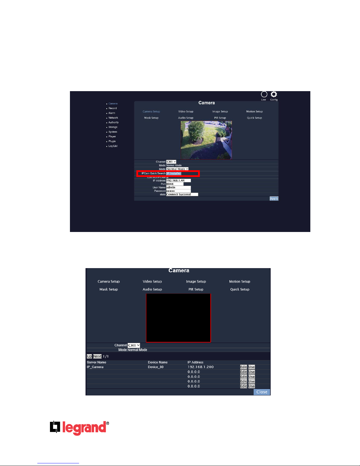
3. Camera
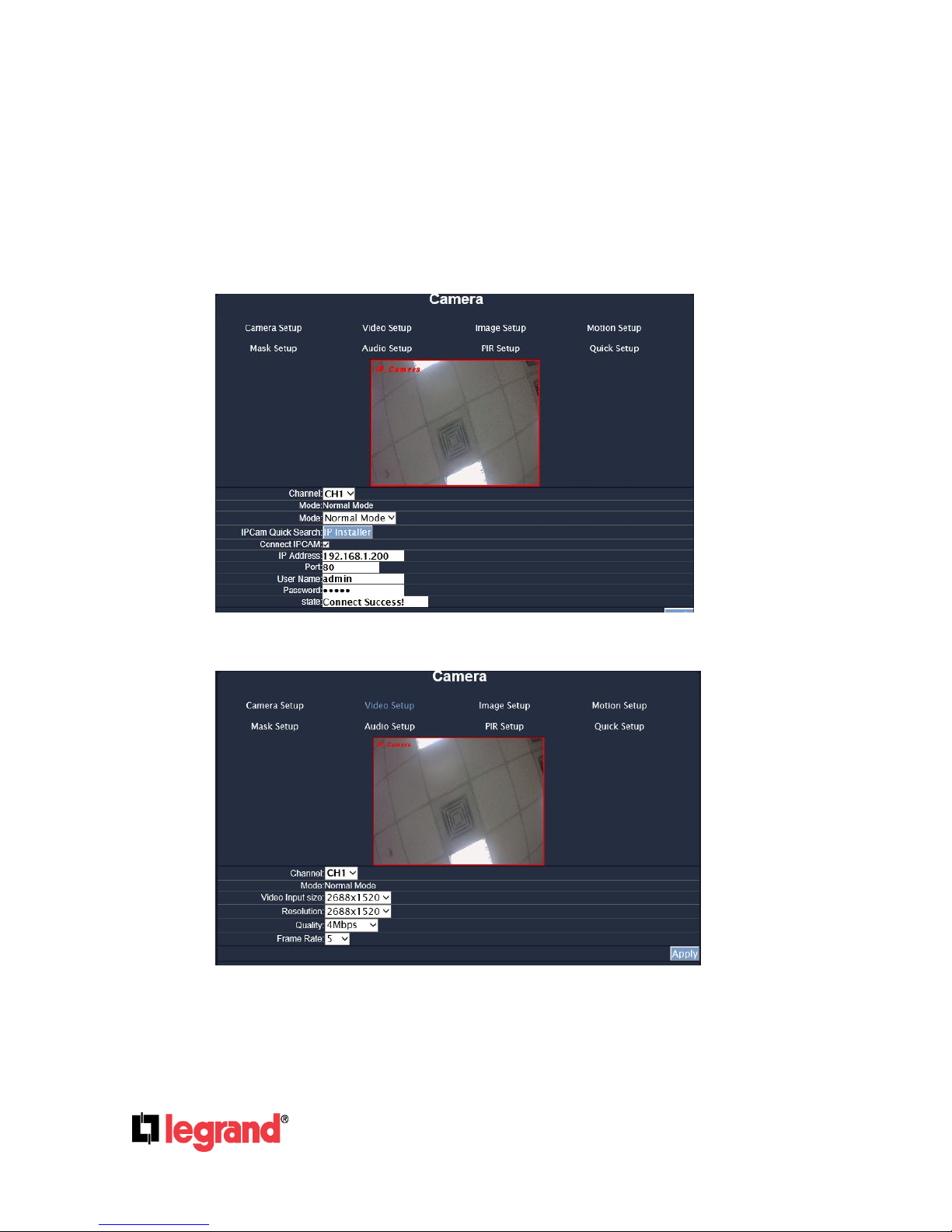
A. Camera Setup
Setup, connect and operate the IP cameras from your NVR. Be sure your IP cameras and NVR are
connected in the same LAN/Network.
Click on IP Installer to start searching for IP cameras on the network.
A-1. IP Installer
Page 14
301 Fulling Mill Road, Suite G
Middletown, PA 17057
(800) 223-4162
©Copyright 2016 by Legrand,
Inc All Rights Reserved.
www.legrand.us
Page 14
The NVR will search for any network device on the same LAN/Network as the NVR. You can edit
the IP address of the IP camera by clicking Edit icon.
The IP camera has to be under the same LAN with NVR in order to be successfully connected.
For example, if the NVR IP address is 192.168.1.33, the IP Cam IP address should be
192.168.1.X.
Click on the Use icon to connect to the IP Camera from the list. If it is connected successfully, the
whole page will return to the Camera Setup page as below.
B. Video Setup
B-1. Channel
Click the drop down list to change the channel of the live video preview.
Page 15

301 Fulling Mill Road, Suite G
Middletown, PA 17057
(800) 223-4162
©Copyright 2016 by Legrand,
Inc All Rights Reserved.
www.legrand.us
Page 15
B-2. Video Input Size
Click the drop down list to change the input size of connecting device.
B-3. Video Input Size
Click the drop down list to change the resolution of connecting device.
B-4. Quality
Click the drop down list to change the image quality.
B-5. Frame Rate
Click drop down list to change the frame rate of connecting device. Click Apply after the quality
rate of the camera is set.
C. Image Setup
C-1. Display
Use the mouse to click enable or disable for the camera display onscreen or not.
C-2. Camera Title
Input the title of the connecting IP device.
C-3. Dwell Time
Press + or - to change auto switch seconds.
C-4. Contrast
Press + or - to change contrast level.
Page 16

301 Fulling Mill Road, Suite G
Middletown, PA 17057
(800) 223-4162
©Copyright 2016 by Legrand,
Inc All Rights Reserved.
www.legrand.us
Page 16
C-5. Brightness
Press + or - to change brightness level.
C-6. Hue
Press + or - to change hue level.
C-7. Saturation
Press + or - to change saturation level.
C-8. Sharpness
Press + or - to change sharpness level.
C-9. Shutter Time
Choose the location of your camera or a fixed shutter time. The shorter the shutter time is the less
light the camera receives and the image becomes darker. Note: When you select a number in
Shutter Time, it will vary in a range corresponding to the camera automatically.
C-10. D-WDR
This function enables the camera to reduce the contrast in the view to avoid dark zones as a
result of over and under exposure.
C-11. Day & Night Mode
There are 3 types of sub-modes under this mode to suit different needs of user’s recording
preference: Color, Auto, and Gray. For Set Time mode, the camera can be operated by the time
this mode has assigned with.
C-12. Night to Day Lux
Click to choose the lux level ranged from 5~50 at night.
C-13. Day to Night Lux
Click to choose the lux level ranged from 1~40 at day time.
Page 17

301 Fulling Mill Road, Suite G
Middletown, PA 17057
(800) 223-4162
©Copyright 2016 by Legrand,
Inc All Rights Reserved.
www.legrand.us
Page 17
D. Motion Setup
D-1. Relay Dwell
Press + or - to change the relay time or disable the relay function.
D-2. Buzzer Dwell
Press + or - to change the buzzer time or disable the buzzer function.
D-3. Area1 / 2 / 3 Sensitivity
Press + or - to change the sensitivity value of motion in 3 Areas from 1, 2, & 3. Click Set and leftclick your mouse button to drag a blue, green, or red area for motion areas.
D-4. Motion Area Setup
The picture above shows how all 3 different areas are set within 3 different frames. Each framed
area is assigned to each color.
All: Set motion detection for the whole area of the screen.
Clear: Clear the area of the current color in the view.
Apply: Save the settings and keep the change.
Page 18

301 Fulling Mill Road, Suite G
Middletown, PA 17057
(800) 223-4162
©Copyright 2016 by Legrand,
Inc All Rights Reserved.
www.legrand.us
Page 18
E. Mask Setup
E-1. Mask1 / 2 / 3
The pictures show how all 3 different areas are set within 3 different colored frames. Tick the
“Mask1/2/3” box and click “Set”. Start dragging your masked areas in blue, green or red by
clicking your mouse anywhere on the screen.
E-2. Masked Area Setup
The picture shows how all 3 different areas are set within 3 different frames. Each framed area is
assigned to each color.
All: Set motion detection for the whole area of the screen.
Clear: Clear the area of the current color in the view.
Apply: Save the settings and keep the change.
The live view will display the masked areas in black blocks.
F. Audio Setup
The channel ticked means the sound from the network camera will be recorded into the playback
video. On the contrary, no sound will be recorded in playback video for the channel not ticked.
Page 19

301 Fulling Mill Road, Suite G
Middletown, PA 17057
(800) 223-4162
©Copyright 2016 by Legrand,
Inc All Rights Reserved.
www.legrand.us
Page 19
G. PIR Setup
Adjust the Buzzer Dwell time and its Interval after the Enable box is ticked.
Please be sure your camera also supports the PIR device.
H. Quick Setup
Other than “Camera Setup”, you can choose another way to complete the IP camera connection job:
using Quick Setup.
H-1. Key-in information manually
All the channels are enlisted and displayed. You can key-in the IP address, port, and the user
name & password of the IP camera. Then assign the channel number. Tick “Enable” to connect to
the IP camera.
Page 20

301 Fulling Mill Road, Suite G
Middletown, PA 17057
(800) 223-4162
©Copyright 2016 by Legrand,
Inc All Rights Reserved.
www.legrand.us
Page 20
H-2. IP CAM Quick Search
With Quick Search, you do not need to type the IP address. Click “IP CAM Quick Search” to enter
the search menu.
The NVR searches for all the IP devices listed in the LAN. Find the IP camera you want to
connect to, assign a channel number for it, and tick “Enable” so for enabling this IP camera and
adding it to all-channel list.
Back to the all-channel list, you can key-in the user name and password, and tick “Enable” to
connect to the camera. If you want to revise the IP setting of a camera, click “Edit”:
The IP Cam has to be under the same LAN with NVR in order to connect successfully. Ex. If the
NVR IP address is 192.168.10.33, the IP Cam IP address should be 192.168.10.X. You can edit
the IP Cam IP address here or on the IP Cam.
If all settings are confirmed, be sure to Save the settings before clicking on Close.
2. Record
A. Pre-Alarm Record Time / Post-Alarm Record Time
Pre-alarm record means the recording before the alarm is triggered; post-alarm record means
the recording after the alarm is triggered. If you set 5 seconds for pre-alarm and 5 seconds for
post-alarm, the alarm recording length will be 10 seconds in total.
Page 21

301 Fulling Mill Road, Suite G
Middletown, PA 17057
(800) 223-4162
©Copyright 2016 by Legrand,
Inc All Rights Reserved.
www.legrand.us
Page 21
B. Mobile Record / Mobile Push Video
Choose “Enable” to begin both the Mobile Record streaming and Mobile Push Video for
mobile viewing.
C. Record Mode
The record mode will be applied to all channels simultaneously. During the recording, the NVR
will record both main streaming and sub streaming from the IP Cam. Use the drop down list to
switch recording modes.
C-1. Manual: In Live mode, click to start recording.
A bar will pop up down below, with the button flickering. Click to stop recording.
C-2. Schedule:
Click on the drop down list from the Record Mode on the right, and select Schedule. There
will be three Setup options available: Schedule Setup, Mail Schedule Setup, and FTP
Schedule Setup.
Page 22

301 Fulling Mill Road, Suite G
Middletown, PA 17057
(800) 223-4162
©Copyright 2016 by Legrand,
Inc All Rights Reserved.
www.legrand.us
Page 22
Users can assign the schedule to any channel by clicking on ALL / CH on top right of each
setup menu. Press + or - to change the channel to apply to.
a. Schedule Setup:
Click the tag “FULL REC” (Red) / “ALARM REC” (Yellow) / “NO REC” (Green), and then draw
on the calendar. The recording type will follow the schedule. The tag “ALARM REC” includes
all the alarm types.
b. Mail Schedule Setup:
Select the time that the recording video is sent to the mail address. No mail will be sent during
“NO MAIL” period even the motion detection is triggered. The tag “ALARM MAIL” refers to
both external alarm and DI from camera.
c. FTP Schedule Setup:
Select the time that the recording video is uploaded to FTP. No file will be uploaded during
“NO MAIL” period even the motion detection is triggered. The tag “ALARM FTP” refers to both
external alarm and DI from camera.
Page 23

301 Fulling Mill Road, Suite G
Middletown, PA 17057
(800) 223-4162
©Copyright 2016 by Legrand,
Inc All Rights Reserved.
www.legrand.us
Page 23
C-3. Alarm Trigger
Start recording when any type of alarm event occurs. The recording video length is according
to the setting of “Pre-Alarm Record Time/Post-Alarm Record Time”.
3. Alarm
A. Alarm Trigger Setup
A-1. Alarm Auto Switch / Auto Switch Timer
Use the drop down list to switch the alarm auto switch. When the alarm is triggered, the screen
will switch to full screen, 4CH split screen or disable. Set the lasting seconds in Auto Switch
Timer for full / split screen modes.
A-2. Video Loss Detection
Use the drop down list to switch the video loss detection. When the video loss is detected, the
alarm will be triggered.
A-3. Digital Input (IP Cam)
Use the drop down list to switch on /off the Digital Input from IP camera. When the DI signal is
received from the camera, the alarm will be triggered.
A-4. Ext. Alarm Detection
Use the drop down list to switch the external alarm detection. When the external alarm is
detected, the alarm will be triggered.
A-5. Ext. Alarm Mode
Use the drop down list to switch the external alarm mode. If the external alarm is setup for
normal open, the option has to switch to N.O.; for the contrary, the option has to switch to N.C.
A-6. HDD Temp Warning
Select Enable from the drop-down list to trigger the buzzer whenever the storage device gets
overheated.
A-7. HDD Temp. Limit Value
Set the temperature limit between 55~70 .
Page 24

301 Fulling Mill Road, Suite G
Middletown, PA 17057
(800) 223-4162
©Copyright 2016 by Legrand,
Inc All Rights Reserved.
www.legrand.us
Page 24
B. Alarm Output Setup
This control item is divided into two parts, “Buzzer Time” and “Relay Time”. The user can press + or
- to switch the external buzzer time and video loss buzzer time in “Buzzer Time” option. The
adjustment value is from 5 to 99 seconds. Moreover, among “Relay Time” option, users can press +
or - to switch the external buzzer time and video loss buzzer time. The adjustment value is also from
5 to 99 seconds.
The Value of Ext. Alarm Buzzer / Relay Time determine the buzzer / relay time of both external
alarm in and digital input (IP Cam).
C. Alarm Event Setup
There are nine types of events that can be selected. When the selected items occur and triggered,
the log will be recorded in the event playback list.
Page 25

301 Fulling Mill Road, Suite G
Middletown, PA 17057
(800) 223-4162
©Copyright 2016 by Legrand,
Inc All Rights Reserved.
www.legrand.us
Page 25
4. Network
A. IP Setup
A-1. IP Mode
A-2. IP Address
A-3. Subnet Mask
A-4. Gateway
A-5. DNS1 & DNS2
A-6. Web Page Port
Select the IP mode from Static IP to DHCP.
Input the NVR IP Address manually if using Static IP.
Input the subnet mask manually which is usually set to 255.255.255.0 if using Static IP.
Input the gateway IP address if using Static IP.
Key-in DNS1 and DNS2 that provided by ISP if using Static IP.
Give the NVR http port for web browser. Default is 80. NOTE: Legrand highly
recommends changing the default port to something other than 80 when attempting
to remote view the NVR.
Page 26

301 Fulling Mill Road, Suite G
Middletown, PA 17057
(800) 223-4162
©Copyright 2016 by Legrand,
Inc All Rights Reserved.
www.legrand.us
Page 26
B. UPNP Port Forwarding
B-1. Enable
Use the checkbox to enable or disable UPNP port setup.
B-2. External HTTP Port
Use the virtual keypad to insert the external http port.
C. PPPoE Setup
C-1. PPPoE Setting
Choose to Enable or Disable PPPoE.
C-2. Username
Insert the user name (ADSL account) which provided from local ISP.
C-3. Password
Insert the password which provided from local ISP.
C-4. Password Confirm
Insert the password again to confirm the password.
C-5. State
Present the current status of PPPoE function.
C-6. IP Address
Input the IP Address.
C-7. Send Mail After Dialed
Click the drop down list to enable or disable the function.
Page 27

301 Fulling Mill Road, Suite G
Middletown, PA 17057
(800) 223-4162
©Copyright 2016 by Legrand,
Inc All Rights Reserved.
www.legrand.us
Page 27
C-8. Subject
Insert the mail subject when dialed successfully.
D. DDNS Setup
D-1. DDNS Setting
Click to enable or disable the DDNS function.
D-2. DDNS Provider
Click the drop down list to select the DDNS server.
D-3. Host Name
Insert the registered host name in the selected provider.
D-4. Username
Insert the registered user name in the selected provider.
D-5. Password
Insert the registered password in the selected provider.
D-6. Schedule Update
A period of time to update IP address.
D-7. State
The state after applied to DDNS.
Updating: Information update.
Idle: Stop service.
DDNS registered successfully, now log by
http://<username>.ddns.camddns.com: Registered successfully.
Updating Failed: the name is already registered.
Page 28

301 Fulling Mill Road, Suite G
Middletown, PA 17057
(800) 223-4162
©Copyright 2016 by Legrand,
Inc All Rights Reserved.
www.legrand.us
Page 28
Updating Failed: please check your internet connection.
E. Mail Server
E-1. Enable
Tick “Trigger Mode” to send video to the mail address when external alarm or DI from IP
Cam is triggered.
E-2. Event Mail
Video Mail
Alarm / Motion / PIR Detection
Sends a video notification via email for Alarm-in and/or Motion detection
Message Mail
Power On:A notification will be sent via email when the NVR starts or reboots.
Start Record:A notification will be sent via email when the NVR starts recording.
Record Error:A notification will be sent via email when the recording fails.
HDD Warning:A notification will be sent via email while recording in the HDD fails.
Video Loss:A notification will be sent via email when image or Internet connection is lost.
Page 29

301 Fulling Mill Road, Suite G
Middletown, PA 17057
(800) 223-4162
©Copyright 2016 by Legrand,
Inc All Rights Reserved.
www.legrand.us
Page 29
F. FTP Server
Stop Record:A notification will be sent via email when the NVR stops recording.
Load Default:A notification will be sent via email when the NVR load the default settings.
E-3. Mail Server
The IP address of Mail Server
E-4. SMTP Port
The port for SMTP (Simple Mail Transfer Protocol). (Default value is 25)
E-5. Username
The username used to log into the mail server.
E-6. Password
The password used to log into the mail server.
E-7. Sender’s Mail
Enter the sender’s account when the mail is sent via this mail server.
E-8. Receiver’s Mail
Enter the receiver’s mail account.
E-9. BCC Mail
Enter the receiver’s BCC mail account.
E-10. Event Subject
Enter the subject of the mail.
E-11. Secure Connection
When ticked, the user can choose connection type between SSL or TLS.
F-1. FTP Setting
Tick ALARM to upload video to FTP when external alarm or DI is triggered.
Tick Motion to upload video to FTP when motion detection is triggered.
Tick PIR DETECTION to upload video to FTP when PIR detection is triggered.
Page 30

301 Fulling Mill Road, Suite G
Middletown, PA 17057
(800) 223-4162
©Copyright 2016 by Legrand,
Inc All Rights Reserved.
www.legrand.us
Page 30
F-2. FTP Server
The IP address of FTP Server.
F-3. Username
The username used to log into the FTP server.
F-4. Password
The password used to log into the FTP server.
F-5. FTP Port
The port number for file transmission protocol. (Default value is 21)
F-6. Path
The ftp path where the user wants to save the information.
Finally, click Test to see if the settings are correct.
G. DHCP Server Setup
G-1. Enabled
Tick the Enabled box to enable or disable the DHCP Server function. Once the function is
activated, the NVR can act as the DHCP server. It will assign or distribute one of the IP
addresses according to the setup IP address range (start and end IP Address.) to the
connecting IP CAM (setup DHCP function).
G-2. Start IP Address
Use the virtual keypad to insert the start IP Address of DHCP server.
G-3. End IP Address
Use the virtual keypad to insert the end IP Address of DHCP server.
G-4. Lease Time
Input the lease time of DHCP server.
Page 31

301 Fulling Mill Road, Suite G
Middletown, PA 17057
(800) 223-4162
©Copyright 2016 by Legrand,
Inc All Rights Reserved.
www.legrand.us
Page 31
H. Status
H-1. POE SWITCH Status:
Click in the POE SWITCH Status button to check on the POE connection status.
I. Connection Status
I-1. Network Connectivity Status
Browse through details of the connection status. You may consider how you want to set up
your streaming mode by acquiring information provided here.
Page 32

301 Fulling Mill Road, Suite G
Middletown, PA 17057
(800) 223-4162
©Copyright 2016 by Legrand,
Inc All Rights Reserved.
www.legrand.us
Page 32
5. Authority
A. HDD Format (Require Password Confirmation)
Tick the box to enable or disable the operation which allows the user to insert the password before
performing the HDD formatting.
B. Anonymous Remote User Login
Tick the box to enable or disable the authority of the anonymous user login. Once enabled, the user
can view the live image via IE browser without having to insert the username/ password.
C. Local User Login (Password Protection)
Tick the box to enable or disable the authority of password protection.
D. Keyboard Lock
Tick the box to enable or disable the control bar of live view.
E. Auto logout when menu closed
Tick the box to enable or disable the operation. Enabling this operation will allow the system to log
out automatically after the menu is closed.
F. User Management
The administrator can set up the user management permission & user authority management.
Page 33

301 Fulling Mill Road, Suite G
Middletown, PA 17057
(800) 223-4162
©Copyright 2016 by Legrand,
Inc All Rights Reserved.
www.legrand.us
Page 33
F-1. Permission
Click on Edit and then tick the checkboxes from the pop-up window to modify the user authority.
F-2. Add User
After clicking the Add User button, the setup page will appear. The administrator can distribute
the authority and the permission for the new user.
Page 34

301 Fulling Mill Road, Suite G
Middletown, PA 17057
(800) 223-4162
©Copyright 2016 by Legrand,
Inc All Rights Reserved.
www.legrand.us
Page 34
6. Storage
A. Overwrite Mode
Select “ON” for the oldest recording data to be overwritten by new recording data. Select
“OFF” for the NVR to stop writing data into the HDD when it is full.
B. HDD Full Warning
Enable this option by setting Overwrite Mode to OFF, and click + or - to change values
from 25% to 5%. When HDD space is less than setting ratio, the buzzer will react.
C. Reserve Mode
Click + or - to setup the active time between 1~30 days.
Page 35

301 Fulling Mill Road, Suite G
Middletown, PA 17057
(800) 223-4162
©Copyright 2016 by Legrand,
Inc All Rights Reserved.
www.legrand.us
Page 35
D. Disk Warning Time
Set up the interval for displaying a warning message regarding the health condition of the
storage device to the user from 1~60 minutes.
E. Storage Information
The information of storage device will be displayed on this page. Your Hard Disk Device
needs to be replaced if its health condition is not displayed as GOOD.
Clicking on GOOD icon to check its status.
F. Format HDD
Page 36

301 Fulling Mill Road, Suite G
Middletown, PA 17057
(800) 223-4162
©Copyright 2016 by Legrand,
Inc All Rights Reserved.
www.legrand.us
Page 36
Insert the username and password while performing the HDD format function. Click Login
to continue.
7. System
A. Information
A-1. Device Name
A-2. MAC Address
A-3. Monitor Resolution
A-4. Reboot
Use the virtual keypad to insert the name of the NVR.
The physical address of the NVR. This is permanent and cannot be changed.
Press + or - to adjust the monitor resolution. Please check the frame rate what your LCD
monitor supports before any adjustment. If you select a resolution not compatible with the LCD
monitor, the system will automatically undo the recent changes.
Click to reboot the NVR.
Page 37

301 Fulling Mill Road, Suite G
Middletown, PA 17057
(800) 223-4162
©Copyright 2016 by Legrand,
Inc All Rights Reserved.
www.legrand.us
Page 37
B. Software Update
B-1. Versions
A list of Firmware Version, WebPlugin Version, and Onvif Version for this NVR is displayed.
B-2. New Firmware
Click on the “browse” button to select the firmware file and then press “Upgrade” button to
upgrade the firmware. Click Network Upgrade button to check whether the firmware version
is the latest.
B-3. Load Default
Load Setup from Default
Click “Apply” to reset the machine and revert all setting back to default value.
Load Setup from
Click “browse” to choose a file. You can load setup from your computer if you ever clicked
“Download” and saved the settings before.
Backup Setup
Click “Download” to save a current setting file to PC. You can apply this file to other NVR so
that the setting will be copied to other NVR.
C. Daylight Saving Time
Page 38

301 Fulling Mill Road, Suite G
Middletown, PA 17057
(800) 223-4162
©Copyright 2016 by Legrand,
Inc All Rights Reserved.
www.legrand.us
Page 38
Edit the start and end daylight saving time. During daylight saving, time will be 1 hour faster.
D. Status Display
Select the items that will be displayed on local NVR.
E. System Setup
Page 39

301 Fulling Mill Road, Suite G
Middletown, PA 17057
(800) 223-4162
©Copyright 2016 by Legrand,
Inc All Rights Reserved.
www.legrand.us
Page 39
E-1. Language
E-2. Device ID
E-3. Date Format
F. Time Setup
Select between NTP, Synchronize with PC’s time, Manual, The date and time remain the same
for setting the server time.
Use the drop down list to change the NVR language.
The ID is used for distinguishing NVRs with a remote controller or RS485. Enter a different ID
when you are operating several NVRs at the same time.
Select a format of date display.
F-1. NTP Setting
Tick the NTP checkbox to enable editing The NTP Server IP address which can only be
modified on local NVR.
F-2. Time Setting
The Time zone can only be modified on local NVR. Tick either Synchronize with PC’s time
or Manual checkbox to activate its time settings.
Page 40

301 Fulling Mill Road, Suite G
Middletown, PA 17057
(800) 223-4162
©Copyright 2016 by Legrand,
Inc All Rights Reserved.
www.legrand.us
Page 40
8. Player
Click the button to download D6Viewer, the NVR recording file player.
A. MAIN SCREEN SETTING (D6 Viewer)
D6Viewer.exe is used for playing the NVR backup video. It can be obtained via the
Internet; or you can simply obtain it by performing USB backup and DVD-RW backup
operation, because the software will be created within the USB device right away.
Open the D6Viewer. Using Overlay mode can improve the system resource performance.
B. HDD PLAY
Reading the NVR HDD from a PC may not be possible since the NVR HDD is in Linux
format, so you need “Ext2Fsd” to assign a drive letter to the HD. You can download it from
Internet.
Start the Ext2Fsd, and it will detects all the disks connected with your PC. Right-click on
the NVR HDD and choose “Change Drive Letter”.
Page 41

301 Fulling Mill Road, Suite G
Middletown, PA 17057
(800) 223-4162
©Copyright 2016 by Legrand,
Inc All Rights Reserved.
www.legrand.us
Page 41
Click “Add”
Assign a letter to the HDD, and then click “OK” so that the HDD get a drive
letter and can be recognized by Windows.
Under HDD Play mode, select the NVR HDD to load the video files inside.
Page 42

301 Fulling Mill Road, Suite G
Middletown, PA 17057
(800) 223-4162
©Copyright 2016 by Legrand,
Inc All Rights Reserved.
www.legrand.us
Page 42
C. File Play
You can open a single video backup file, select "File->File Play”. Then “Open".
Choose the path the .haX file reserved and pick the file to playback.
Page 43

301 Fulling Mill Road, Suite G
Middletown, PA 17057
(800) 223-4162
©Copyright 2016 by Legrand,
Inc All Rights Reserved.
www.legrand.us
Page 43
Press the play icon to play the video or pause picture.
D. PLAYBACK OPERATION
D-1. TIME SEARCH
Select the Date and Time and then click to play the video.
Page 44

301 Fulling Mill Road, Suite G
Middletown, PA 17057
(800) 223-4162
©Copyright 2016 by Legrand,
Inc All Rights Reserved.
www.legrand.us
Page 44
D-2. EVENT SEARCH
After pressing the button, it will display all the events which are saved within
the NVR HDD (Shown in the following image).
E. LOG
Click to check the log records.
Page 45

301 Fulling Mill Road, Suite G
Middletown, PA 17057
(800) 223-4162
©Copyright 2016 by Legrand,
Inc All Rights Reserved.
www.legrand.us
Page 45
F. ZOOM
Tick the “Zoom” box and drag an area on the screen, then click the area to zoom in.
Page 46

301 Fulling Mill Road, Suite G
Middletown, PA 17057
(800) 223-4162
©Copyright 2016 by Legrand,
Inc All Rights Reserved.
www.legrand.us
Page 46
G. BACKUP FILE TO MKV OR AVI FORMAT
MKV
AVI
There are two types of video formats: MKV and AVI. With AVI file, you can choose to either
include Time Stamp and Audio or not.
After double-clicking on one specific channel display image, the ‘File Convert’ button will
be available. Select the type of video format you would like to convert to from the Backup
drop down list.
Click on button to begin the backup.
A window will pop up. Enter a file name and edit the file path directory.
While the converting is in process, you may press the button to pause at any
time before it is completed.
Page 47

301 Fulling Mill Road, Suite G
Middletown, PA 17057
(800) 223-4162
©Copyright 2016 by Legrand,
Inc All Rights Reserved.
www.legrand.us
Page 47
9. Plugin
Click the button to download Plugin for running the NVR system on PC.
10. Log List
A. System Log: Click to view the system log and change settings.
B. Event Log: Click to view events.
 Loading...