

LEGRAND CHIEF LF49UxP, CHIEF LF50UxP, CHIEF LF55UxP, CHIEF LF50UxP-B2B, CHIEF LF55UxP-B2B Installation Instructions Manual
...Page 1
INSTALLATION INSTRUCTIONS
LF49UxP
LF55UxP-B2B
Back-to-Back Floor Kiosk
Floor Kiosk
49"/50"/55" Portrait Floor Kiosks,
49"/50"/55" Portrait Back-to-Back Floor Kiosks
Portuguese Product Description
Italian Product Description
Dutch Product Description
LF49/50/55UxP,
LF49/50/55UxP-B2B
Page 2
LF49/50/55UxP, LF49/50/55UxP-B2B Installation Instructions
DISCLAIMER
Legrand | AV and its affiliated corporations and subsidiaries
(collectively “Legrand | AV”), intend to make this manual
accurate and complete. However, Legrand | AV makes no claim
that the information contained herein covers all details,
conditions or variations, nor does it provide for every possible
contingency in connection with the installation or use of this
product. The information contained in this document is subject
to change without notice or obligation of any kind. Legrand | AV
makes no representation of warranty, expressed or implied,
regarding the information contained herein. Legrand | AV
assumes no responsibility for accuracy, completeness or
sufficiency of the information contained in this document.
Chief® is a registered trademark of Legrand AV Inc.
DEFINITIONS
MOUNTING SYSTEM: A MOUNTING SYSTEM is the
primary Chief product to which an accessory and/or component
is attached.
ACCESSORY: AN ACCESSORY is the secondary Chief
product which is attached to a primary Chief product, and may
have a component attached or setting on it.
COMPONENT: A COMPONENT is an audiovisual item
designed to be attached or resting on an accessory or mounting
system such as a video camera, CPU, screen, display,
projector, etc.
WARNING: Do NOT install floor kiosks and back-to-back
floor kiosks to any surface other than concrete! Concrete
flooring must be at least 4" in thickness and NOT be covered
with any other type of flooring material. Concrete anchors
must be installed directly into concrete surface.
WARNING: Exceeding the weight capacity can result in
serious personal injury or damage to equipment! It is the
installer’s responsibility to make sure the weight of
components attached to swing door(s) does not exceed:
• LF49/50/55UxP Models: 125 lbs (56.7 kg)
Removable storage panel capacity: 25 lbs (11.3 kg);
• LF49/50/55UxP-B2B Models: 125 lbs (56.7 kg) per
screen
Removable storage panel capacity: 25 lbs (11.3 kg).
The hinge-open position is for installation and service only.
WARNING: Use this mounting system only for its intended
use as described in these instructions. Do not use
attachments not recommended by the manufacturer.
WARNING: Never operate this mounting system if it is
damaged. Return the mounting system to a service center for
examination and repair.
WARNING: A WARNING alerts you to the possibility of
serious injury or death if you do not follow the instructions.
CAUTION: A CAUTION alerts you to the possibility of
damage or destruction of equipment if you do not follow the
corresponding instructions.
IMPORTANT SAFETY INSTRUCTIONS
WARNING: Failure to read, thoroughly understand, and
follow all instructions can result in serious personal injury,
damage to equipment, or voiding of factory warranty! It is the
installer’s responsibility to make sure all mounting systems
are properly assembled and installed using the instructions
provided.
WARNING: Failure to provide adequate structural strength
for this mounting system can result in serious personal injury
or damage to equipment! It is the installer’s responsibility to
make sure the structure to which this mounting system is
attached can support five times the combined weight of all
equipment. Reinforce the structure as required before
installing the mounting system.
WARNING: Do not use this mounting system outdoors.
--SAVE THESE INSTRUCTIONS--
2
Page 3
Installation Instructions LF49/50/55UxP, LF49/50/55UxP-B2B
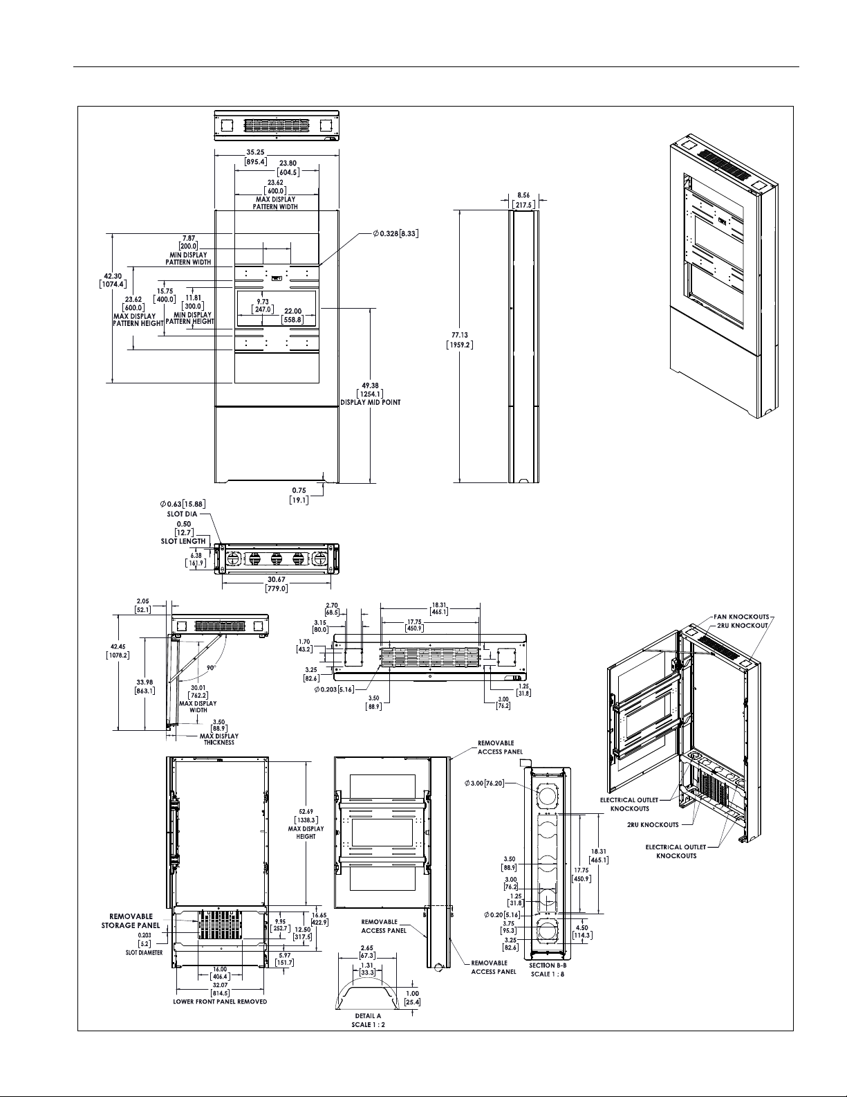
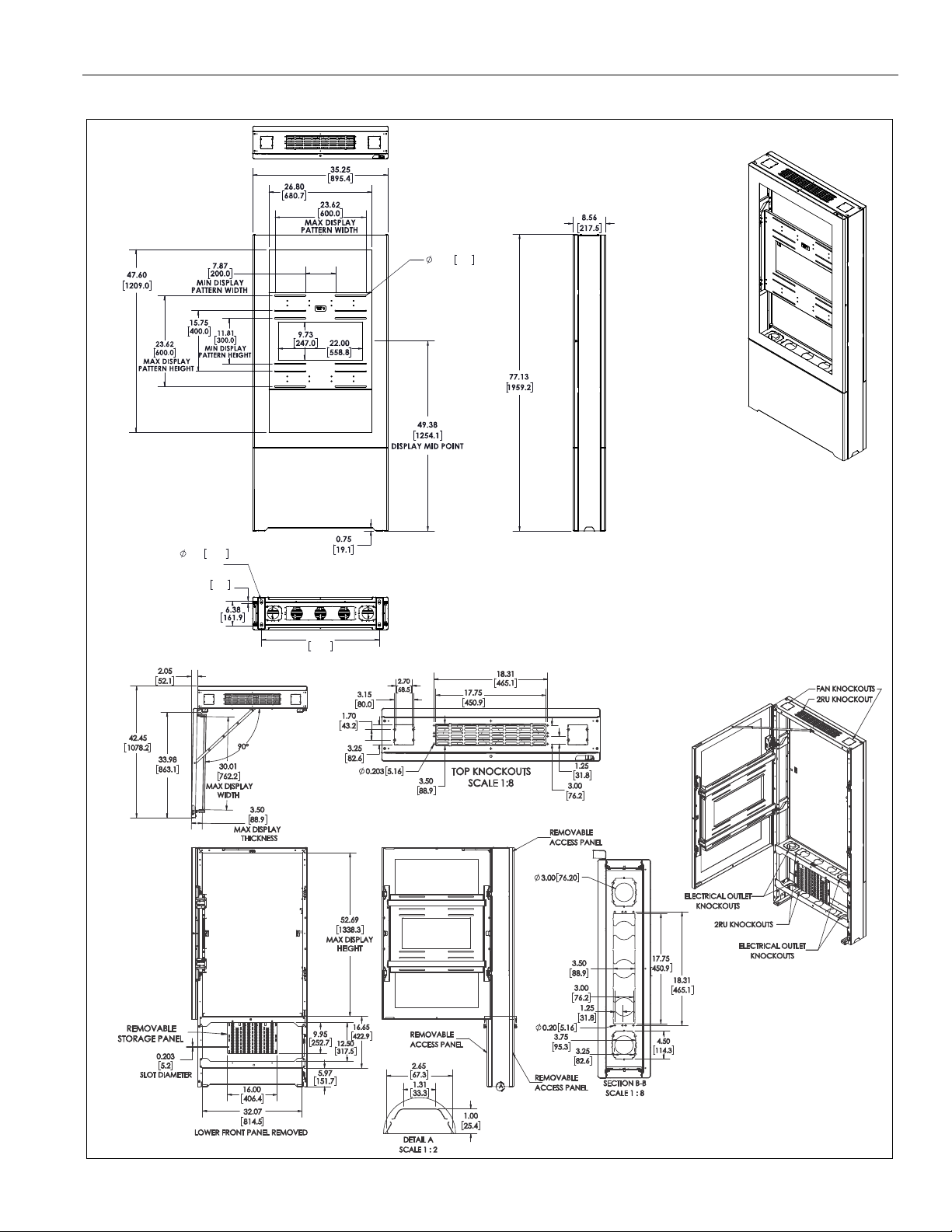
TOP KNOCKOUTS
SCALE 1:8
FLOOR MOUNTING
HOLES
DIMENSIONS: INCH
[MILLIMETERS]
LF49UxP
DIMENSIONS
3
Page 4
LF49/50/55UxP, LF49/50/55UxP-B2B Installation Instructions
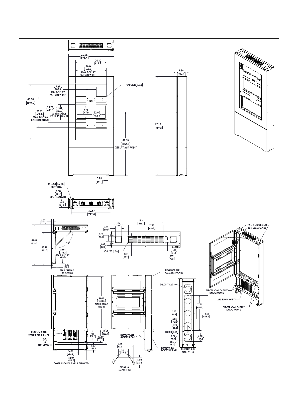
FLOOR MOUNTING
HOLES
TOP KNOCKOUTS
SCALE 1:8
LF50UxP
DIMENSIONS: INCH
[MILLIMETERS]
DIMENSIONS...cont’d
4
Page 5
Installation Instructions LF49/50/55UxP, LF49/50/55UxP-B2B
0.328 8.33
0.63 15.88
SLOT DIA
0.50
12.7
SLOT LENGTH
30.67
779.0
FLOOR MOUNTING
HOLES
DIMENSIONS: INCH
[MILLIMETERS]
LF55UxP
DIMENSIONS...cont’d
5
Page 6
LF49/50/55UxP, LF49/50/55UxP-B2B Installation Instructions
REMOVABLE
STORAGE PANEL
LOWER FRONT PANEL REMOVED
3.00
76.20
SECTION B-B
SCALE 1 : 8
0.203 5.16
TOP KNOCKOUTS
SCALE 1:8
0.20
5.16
0.328 8.33
0.63 15.88
SLOT DIA
0.50
12.7
SLOT LENGTH
30.67
779.0
FLOOR MOUNTING
HOLES
DIMENSIONS: INCH
[MILLIMETERS]
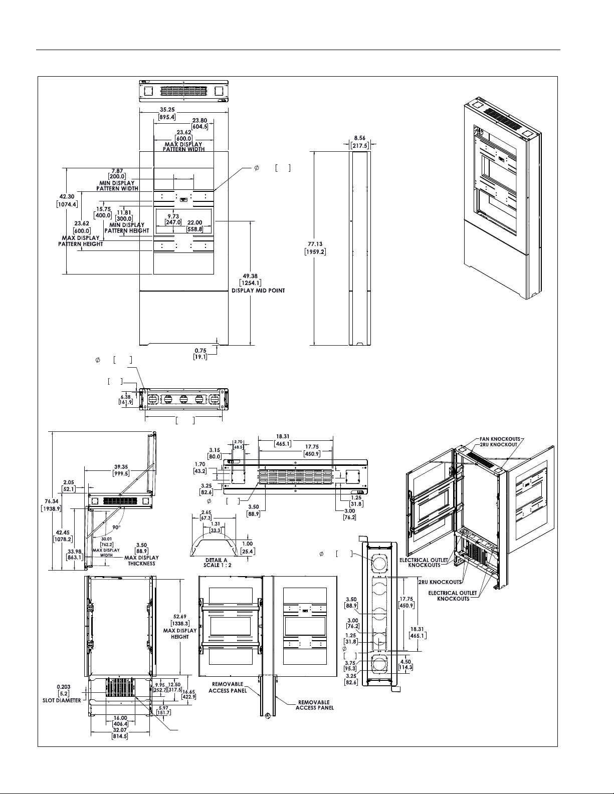
LF49UxP-B2B
DIMENSIONS...cont’d
6
Page 7

Installation Instructions LF49/50/55UxP, LF49/50/55UxP-B2B
REMOVABLE
STORAGE PANEL
LOWER FRONT PANEL REMOVED
3.00
76.20
0.20 5.16
SECTION B-B
SCALE 1 : 8
0.203 5.16
TOP KNOCKOUTS
SCALE 1:8
0.328 8.33
0.63 15.88
SLOT DIA
0.50
12.7
SLOT LENGTH
30.67
779.0
FLOOR MOUNTING
HOLES
DIMENSIONS: INCH
[MILLIMETERS]
LF50UxP-B2B
DIMENSIONS...cont’d
7
Page 8

LF49/50/55UxP, LF49/50/55UxP-B2B Installation Instructions
REMOVABLE
STORAGE PANEL
LOWER FRONT PANEL REMOVED
3.00
76.20
0.20 5.16
SECTION B-B
SCALE 1 : 8
0.203 5.16
TOP KNOCKOUTS
SCALE 1:8
0.328 8.33
0.63 15.88
SLOT DIA
0.50
12.7
SLOT LENGTH
30.67
779.0
FLOOR MOUNTING
HOLES
DIMENSIONS: INCH
[MILLIMETERS]
LF55UxP-B2B
DIMENSIONS...cont’d
8
Page 9

Installation Instructions LF49/50/55UxP, LF49/50/55UxP-B2B
Tighten Fastener
Apretar elemento de fijación
Befestigungsteil festziehen
Apertar fixador
Serrare il fissaggio
Bevestiging vastdraaien
Serrez les fixations
Loosen Fastener
Aflojar elemento de fijación
Befestigungsteil lösen
Desapertar fixador
Allentare il fissaggio
Bevestiging losdraaien
Desserrez les fixations
Phillips Screwdriver
Destornillador Phillips
Kreuzschlitzschraubendreher
Chave de fendas Phillips
Cacciavite a stella
Kruiskopschroevendraaier
Tournevis à pointe cruciforme
Open-Ended Wrench
Llave de boca
Gabelschlüssel
Chave de bocas
Chiave a punte aperte
Steeksleutel
Clé à fourche
By Hand
A mano
Von Hand
Com a mão
A mano
Met de hand
À la main
Hex-Head Wrench
Llave de cabeza hexagonal
Sechskantschlüssel
Chave de cabeça sextavada
Chiave esagonale
Zeskantsleutel
Clé à tête hexagonale
Pencil Mark
Marcar con lápiz
Stiftmarkierung
Marcar com lápis
Segno a matita
Potloodmerkteken
Marquage au crayon
Drill Hole
Perforar
Bohrloch
Fazer furo
Praticare un foro
Gat boren
Percez un trou
Adjust
Ajustar
Einstellen
Ajustar
Regolare
Afstellen
Ajuster
Remove
Quitar
Entfernen
Remover
Rimuovere
Verwijderen
Retirez
Optional
Opcional
Optional
Opcional
Opzionale
Optie
En option
Security Wrench
Llave de seguridad
Sicherheitsschlüssel
Chave de segurança
Chiave di sicurezza
Veiligheidssleutel
Clé de sécurité
LEGEND
9
Page 10

LF49/50/55UxP, LF49/50/55UxP-B2B Installation Instructions
3/8"
#2
1/2"
5/16"
BA (4/8)
M4 x 12mm
BD (4/8)
BG (4/8)
M6 x 12mm
BJ (4/8)
M8 x 12mm
BB (4/8)
M4 x 25mm
BC (4/8)
M4 x 50mm
BE (4/8)
M5 x 25mm
BF (4/8)
M5 x 50mm
BH (4/8)
M6 x 25mm
BI (4/8)
M6 x 50mm
BK (4/8)
M8 x 25mm
BL (4/8)
M8 x 50mm
BM (8/16)
.750x.344x.500"
BO (4/8)
[universal washer]
BN (8/16)
.750x.323x.250"
OR
A (1)
LFxxUxP
[LF49UxP shown
as example]
A (1)
LFxxUxP-B2B
[LF49UxP-B2B
shown as example]
OR
C (1)
[Storage panel]
D (2/4 rolls)
Gasket strip,
1/2" wide
Monitor Interface Hardware Bag
E (4/4)
3/8" x 3"
F (2/2)
10-24 x 3/16"
G (3/6)
[Cable tie mount]
H (6/12)
[Cable tie, 7-1/2"]
NOTE: Letters match markings on hardware bags
*Quantities are listed as (LFxxUxP / LFxxUxP-B2B)
M5 x 12mm
TOOLS REQUIRED FOR INSTALLATION
PARTS
10
Page 11

Installation Instructions LF49/50/55UxP, LF49/50/55UxP-B2B
1
Key ships
taped in
this area
2
Swing door
lock
Swing
door
[LF49/50/55UxP shown as example]
3
3
4
4
5
5
6
Rear panel
Lower panels
Lower panel
latch
Flag locks
[LF49/50/55UxP shown as example]
7
7
8
ASSEMBLY AND INSTALLATION
Remove Kiosk from Packaging
NOTE: These instructions apply to both the LF49/50/55UxP
(one-sided display) and LF49/50/55UxP-B2B models
(two-sided display), unless otherwise noted. If installing
a -B2B, simply repeat the installation steps on both
sides of the kiosk, unless otherwise noted.
NOTE: The packaging film on the kiosk should remain in place
as long as possible during the kiosk installation to avoid
scratching the kiosk. Remove packaging film after
installation is complete.
1. Remove key from display frame. (See Figure 1)
2. Use the key to unlock and open the swing door. (See Figure 1)
3. Lift up the lower panel latch to release lower panel. Lift up
opposite lower panel latch to release the opposite lower
panel. (See Figure 2)
4. Remove both lower panels by pulling out 1" - 2" on the latch
side of each lower panel. (See Figure 2)
5. Slide each panel to the non-latch side to remove lower
panels. (See Figure 2)
6. (One-sided display only) Raise the flag lock on the inside
of each side of the rear panel. (See Figure 2)
7. (One-sided display only) Grasp and "squeeze" the sides
of the rear panel from behind the kiosk.
8. (One-sided display only) Lift to remove the rear panel from
the kiosk. (See Figure 2)
Figure 1
Figure 2
11
Page 12

LF49/50/55UxP, LF49/50/55UxP-B2B Installation Instructions
9
x 4
[LF49/50/55UxP shown as example]
1
2
E x 4
5
6
(E x 4)
2
3/8”
3-1/2” deep
3
air
(E) x 4
5
(A)
(E) x 4
6
(A)
hose
WARNING: TIPPING HAZARD! Close and lock door(s)
before removing the hex head bolts from the pallet. (See
Figure 3) Keep door(s) closed and locked until the kiosk is
fully secured to the floor. Kiosk may tip if door(s) are open
when kiosk is not securely fastened to pallet or to floor.
9. Remove and discard the four hex head bolts and washers
connecting the kiosk to the pallet, and lift kiosk off wood
pallet. (See Figure 3)
Figure 3
Bolt Kiosk to Floor
1. Using kiosk (A) as a template, mark center of four mounting
2. Using a 3/8” drill bit, drill a hole 3-1/2” in depth at each
3. Blow each hole clean of any concrete debris with an air
WARNING: Do NOT install floor kiosks and back-to-back
floor kiosks to any surface other than concrete! Concrete
flooring must be at least 4" in thickness and NOT be covered
with any other type of flooring material. Concrete anchors
must be installed directly into concrete surface.
holes (the holes where kiosk was attached to pallet) and
move kiosk to allow access to drill holes. (See Figure 4)
marked location. (See Figure 4) and (See Figure 5)
hose or compressed air in a can. (See Figure 5)
IMPORTANT ! : Do NOT modify the anchors or advance
the bolt in the anchors prior to installation!
4. Place kiosk (A) on top of drilled holes making sure that
drilled holes are centered within the mounting holes in
12
kiosk.
Figure 4
5. Use a hammer to drive anchors (E) through kiosk mounting
holes into the drilled holes until the bolt head is firmly seated
against the kiosk. (See Figure 4) and (See Figure 5)
6. Tighten each anchor by turning the head three to four turns
past finger tight. (See Figure 5)
Figure 5
7. Repeat Steps 5 and 6 for each mounting hole.
Page 13

Installation Instructions LF49/50/55UxP, LF49/50/55UxP-B2B
1
1
x 2
1
x 2
Display
frame
[LF49/50/55UxP shown as example]
3
(D)
Swing
Leave approximately
1/16" space between
edge of opening
and gasket strip
door
(D) Gasket strip
[View of swing door - inside]
Attaching Flat Panel
NOTE:
1. Use a 5/16" open end wrench to remove display frame from
Use the key to unlock and open the swing door.
kiosk swing door by removing and SAVING four hex head
screws. (See Figure 6)
Figure 6
2. Clean the inside edge of the swing door (approximately one
inch depth around entire opening) with an alcohol wipe or
something similar, and let dry. (See Figure 7)
3. Install gasket strip (D) around inside edge of swing door
opening. (See Figure 7)
NOTE: Do not install gasket strip right up to edge. The gasket
strip should be placed approximately 1/16" away from
opening.
Figure 7
4. Carefully place flat panel face down on a soft, non-abrasive
surface.
WARNING: IMPROPER INSTALLATION CAN LEAD TO
DISPLAY FALLING CAUSING SERIOUS PERSONAL
INJURY OR DAMAGE TO EQUIPMENT! Using screws of
improper size may damage your display. Properly sized
screws will easily and completely thread into display
mounting holes. If spacers are required, be sure to use longer
screws of the same diameter.
5. Select screw diameter by examining hardware (BA-BL) and
comparing with mounting holes on flat panel.
6. Select spacers:
• Spacers are NOT
recessed and display frame can lay flat against flat
panel.
required if mounting holes are not
• Spacers (BM, BN) ARE required if mounting holes are
recessed, or if protrusions prevent display frame from
laying flat.
• Spacers may also be used between the display frame
and flat panel to create more space for AV
components, or to accommodate thinner flat panels.
7. Select screw length:
• By hand, insert SHORTEST length screw of selected
diameter (BA, BD, BG, or BJ) through universal washer
(BO--if required), display frame, spacer (BM, BN--if
required), into flat panel mounting hole. Do NOT thread
screw into hole at this time.
13
Page 14

LF49/50/55UxP, LF49/50/55UxP-B2B Installation Instructions
NOTE: Use universal washer (BO)
(BO)
(BM and/or BN)
9
(BA-BL) x 4
ONLY with M4, M5 or
M6 screws.
Display
Display
frame
10
x 4
Slots for depth adjustment
IMPORTANT ! : The M8 screws do NOT require a
washer. Use the universal washer (BO) ONLY with the
M4, M5 or M6 screws.
• Proper screw length requires base of screw head to
protrude above flat washer a distance equal to or
greater than the screw diameter. If screw length is
inadequate, select longer screw. Select shortest screw
which will protrude the required distance.
NOTE: Measure display area offsets from edges of display,
and use that information to assist in centering display
area on the display frame.
8. Place display frame onto back of flat panel and match the
VESA pattern on flat panel to the display frame mounting
slots. (See Figure 8)
9. Use selected screws (BA-BL), washers (BO--if required),
and spacers (BM, BN--if required), to connect display frame
to back of flat panel. (See Figure 8)
NOTE: Before fully tightening screws use previously measured
display offset information to center display area relative
to display frame.
Figure 8
10. Reattach the display frame to the kiosk using a 5/16"
wrench and the four hex head screws removed in Step 1.
(See Figure )
NOTE: The slots on the ends of the display frame allow
adjustment, as needed, to accommodate the depth of
the display.
Figure 9
14
Page 15

Installation Instructions LF49/50/55UxP, LF49/50/55UxP-B2B
Possible locations
for cable tie mounts.
This area may also
be used to place
cables, but may be
too tight for certain
cables
1
2
(F) x 2
3
Cabling
1. Cables may be placed through the corners of the display
frame. (See Figure 10)
2. Attach cable tie mounts (G) as necessary to keep cables
from being damaged in pinch points of the kiosk. (See
Figure 10)
IMPORTANT ! : Avoid pinching the cables inside the
kiosk. Damage to cables may occur.
Storage Panel
WARNING: Exceeding the weight capacity can result in
serious personal injury or damage to equipment! It is the
installer’s responsibility to make sure the weight of
components attached to the storage panel does not exceed
25 lbs (11.3 kg).
1. Install AV component(s) to the storage panel (C) using the
hardware and instructions included with the component(s).
Either screws or cable ties may be used to fasten
component(s) to the panel.
2. Place storage panel (C) inside the kiosk, lining up the holes
in the storage panel with the holes in the lower part of the
kiosk. (See Figure 11)
3. Hold storage panel (C) directly behind screw holes and
fasten using two 10-24 x 3/16" Phillips screws (F). (See
Figure 11)
Figure 10
Figure 11
15
Page 16

LF49/50/55UxP, LF49/50/55UxP-B2B Installation Instructions
4
5
5
4
5
6
7
8
9
10
Figure 12
4. Return lower panel to kiosk by sliding it in from the left side
of the kiosk. (See Figure 12)
5. Pull up lower panel latch inside kiosk and push in right side of
lower panel to complete installation of panel. (See Figure 12)
6.
(One-sided display only)
panel and lift upward approximately 2 inches. (See Figure 12)
7. (One-sided display only) Press rear panel in at top.
8. (One-sided display only) Press lower part of rear panel
into kiosk.
9. (One-sided display only) Lower the flag lock on the inside
of each side of the rear panel.
Rest rear panel on top of lower
NOTE: Kiosk will NOT shut if it is locked. Be sure to move lock
to unlocked position before proceeding.
10. Push door bracket at top of kiosk to assist in closing kiosk
door. (See Figure 13)
11. Complete closing the kiosk, and turn key to lock it.
Figure 13
16
Page 17

Installation Instructions LF49/50/55UxP, LF49/50/55UxP-B2B
17
Page 18

LF49/50/55UxP, LF49/50/55UxP-B2B Installation Instructions
18
Page 19

Installation Instructions LF49/50/55UxP, LF49/50/55UxP-B2B
19
Page 20

LF49/50/55UxP, LF49/50/55UxP-B2B Installation Instructions
8800-003146 Rev01
2019 Legrand | AV
www.legrandav.com
10/19
USA/International A 6436 City West Parkway, Eden Prairie, MN 55344
P 800.582.6480 / 952.225.6000
F 877.894.6918 / 952.894.6918
Europe A Franklinstraat 14, 6003 DK Weert, Netherlands
P +31 (0) 495 580 852
F +31 (0) 495 580 845
Asia Pacific A Office No. 918 on 9/F, Shatin Galleria
18-24 Shan Mei Street
Fotan, Shatin, Hong Kong
P 852 2145 4099
F 852 2145 4477
 Loading...