

Page 1
I N S T A L L A T I O N I N S T R U C T I O N S
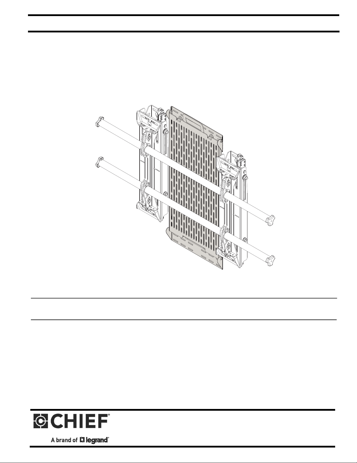
Component Storage Panel
(CSPR with Fusion wall mount and FCAV1U accessory)
Spanish Product Description
German Product Description
Portuguese Product Description
Italian Product Description
Dutch Product Description
French Product Description
CSPS/CSPR
Page 2
CSPS/CSPR Installation Instructions
DISCLAIMER
Legrand | AV and its affiliated corporations and subsidiaries
(collectively “Legrand | AV”), intend to make this manual
accurate and complete. However, Legrand | AV makes no claim
that the information contained herein covers all details,
conditions or variations, nor does it provide for every possible
contingency in connection with the installation or use of this
product. The information contained in this document is subject
to change without notice or obligation of any kind. Legrand | AV
makes no representation of warranty, expressed or implied,
regarding the information contained herein. Legrand | AV
assumes no responsibility for accuracy, completeness or
sufficiency of the information contained in this document.
Chief® is a registered trademark of Legrand AV Inc.
DEFINITIONS
MOUNTING SYSTEM: A MOUNTING SYSTEM is the
primary Chief product to which an accessory and/or component
is attached.
WARNING: Exceeding the weight capacity can result in
serious personal injury or damage to equipment! It is the
installer’s responsibility to make sure the combined weight of
all components attached to this accessory does not exceed
20 lbs (9.07 kg).
WARNING: Use this accessory only for its intended use as
described in these instructions. Do not use attachments not
recommended by the manufacturer.
WARNING: Never operate this accessory if it is damaged.
Return the accessory to a service center for examination and
repair.
WARNING: Do not use this accessory outdoors.
ACCESSORY: AN ACCESSORY is the secondary Chief
product which is attached to a primary Chief product, and may
have a component attached or setting on it.
COMPONENT: A COMPONENT is an audiovisual item
designed to be attached or resting on an accessory or mounting
system such as a video camera, CPU, screen, display,
projector, etc.
WARNING: A WARNING alerts you to the possibility of
serious injury or death if you do not follow the instructions.
CAUTION: A CAUTION alerts you to the possibility of
damage or destruction of equipment if you do not follow the
corresponding instructions.
IMPORTANT SAFETY INSTRUCTIONS
WARNING: Failure to read, thoroughly understand, and
follow all instructions can result in serious personal injury,
damage to equipment, or voiding of factory warranty! It is the
installer’s responsibility to make sure all accessories are
properly assembled and installed using the instructions
provided.
WARNING: RISK OF INJURY TO PERSONS! Do not use
this accessory to support video equipment such as
televisions or computer monitors.
--SAVE THESE INSTRUCTIONS--
WARNING: Failure to provide adequate structural strength
for this accessory can result in serious personal injury or
damage to equipment! It is the installer’s responsibility to
make sure the structure to which this accessory is attached
can support five times the combined weight of all equipment.
Reinforce the structure as required before installing the
accessory. The wall to which the accessory is being attached
may have a maximum drywall thickness of 5/8” (1.6cm). Do
not install drywall anchors into the seam between drywall
pieces.
2
Page 3
Installation Instructions CSPS/CSPR
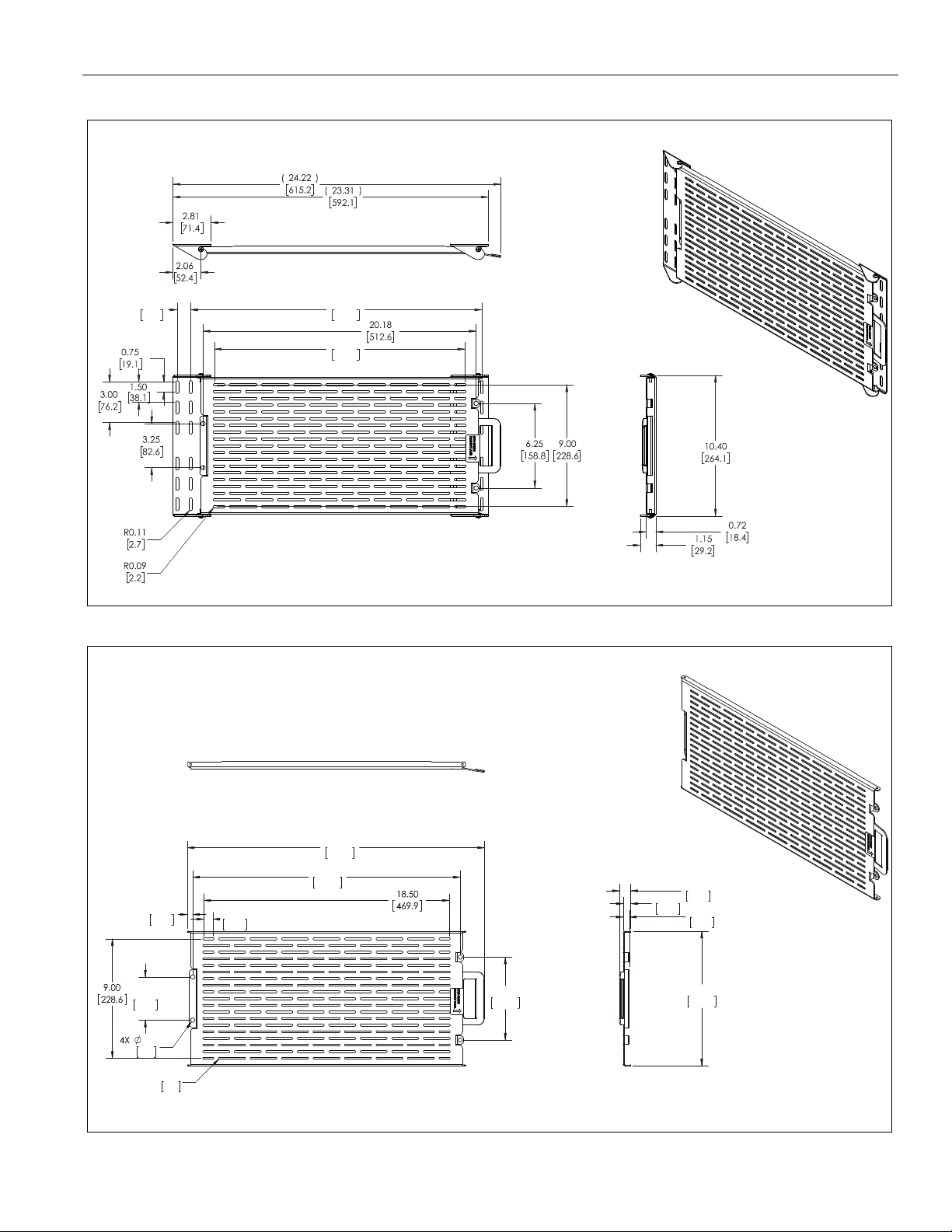
DIMENSIONS
CSPR
21.50
546.1
18.50
469.9
1.00
25.4
CSPS
3.25
82.6
7.9
0.31
0.41
10.4
R0.07
1.9
(
)
22.41
569.1
20.18
512.6
0.69
17.5
6.25
158.8
(
)
0.86
21.9
0.57
14.6
0.46
11.8
10.15
257.8
3
Page 4
CSPS/CSPR Installation Instructions
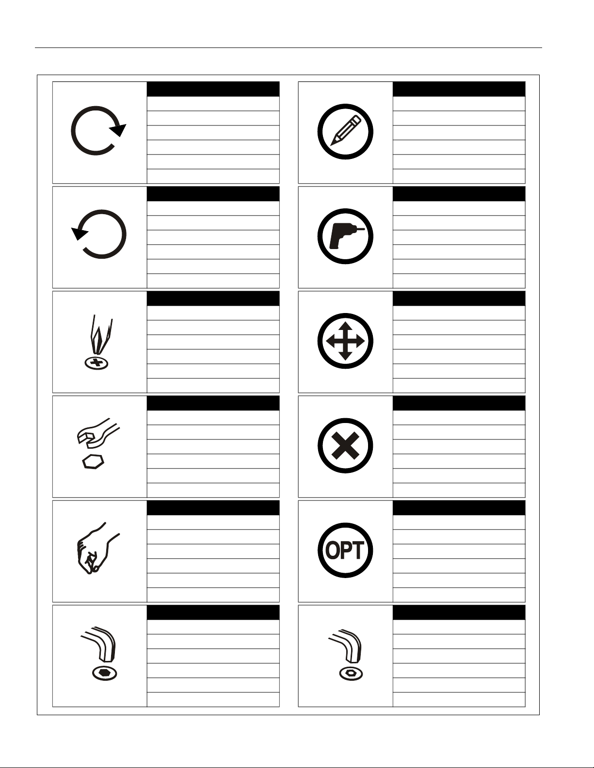
LEGEND
Tighten Fastener
Apretar elemento de fijación
Befestigungsteil festziehen
Apertar fixador
Serrare il fissaggio
Bevestiging vastdraaien
Serrez les fixations
Loosen Fastener
Aflojar elemento de fijación
Befestigungsteil lösen
Desapertar fixador
Allentare il fissaggio
Bevestiging losdraaien
Desserrez les fixations
Phillips Screwdriver
Destornillador Phillips
Kreuzschlitzschraubendreher
Chave de fendas Phillips
Cacciavite a stella
Kruiskopschroevendraaier
Tournevis à pointe cruciforme
Pencil Mark
Marcar con lápiz
Stiftmarkierung
Marcar com lápis
Segno a matita
Potloodmerkteken
Marquage au crayon
Drill Hole
Perforar
Bohrloch
Fazer furo
Praticare un foro
Gat boren
Percez un trou
Adjust
Ajustar
Einstellen
Ajustar
Regolare
Afstellen
Ajuster
Open-Ended Wrench
Llave de boca
Gabelschlüssel
Chave de bocas
Chiave a punte aperte
Steeksleutel
Clé à fourche
By Hand
A mano
Von Hand
Com a mão
A mano
Met de hand
À la main
Hex-Head Wrench
Llave de cabeza hexagonal
Sechskantschlüssel
Chave de cabeça sextavada
Chiave esagonale
Zeskantsleutel
Clé à tête hexagonale
Remove
Quitar
Entfernen
Remover
Rimuovere
Verwijderen
Retirez
Optional
Opcional
Optional
Opcional
Opzionale
Optie
En option
Security Wrench
Llave de seguridad
Sicherheitsschlüssel
Chave de segurança
Chiave di sicurezza
Veiligheidssleutel
Clé de sécurité
4
Page 5

Installation Instructions CSPS/CSPR
TOOLS REQUIRED FOR INSTALLATION
#2
PARTS
1/2" (12.7mm)
5/32" (security)
(included)
With CSPR (ONLY)
B (2)
[Wall bracket]
With CSPS (ONLY)
J (4)
1/4"-20 anchor
A (1)
[Accessory wall plate]
K (4)
1/4-20 x 1 3/4"
L (4)
1/4"
C (4)
#10-24 anchor
F (4)
#10-24 x 3/4"
D (4)
#10-24 x 1 1/4"
G (2)
#10-24 x 1/2"
(security)
E (4)
#10
H (1)
5/32"
(security)
5
Page 6

CSPS/CSPR Installation Instructions
Site Requirements
Component Storage Panel Installation Location
If back side of wall is unfinished, drywall must be installed
to a minimum of one stud left and right of the studs
being used to install the mount. Drywall must be
secured to studs with screws 12" on center
Drywall
**1/2" minimum
Drywall Thickness
(Both Sides of Stud)
**See hazard statement
on page 2!
There must be a minimum of
1-7/8" (48mm) clearance
inside wall
FRONT
Steel Stud (2 x 4 / 25ga minimum)
Stud type and structural strength must conform to the North American
Specification for the Design of Cold-Formed Steel Structural Members.
[362, 125 18, C-Shape, S - Stud Section]
6
Page 7

Installation Instructions CSPS/CSPR
Drywall
Assembly And Installation
CSPS Installation
1. Position accessory wall plate (A) onto wall at desired
mounting location. Use a level to ensure of an even mount.
(See Figure 1)
2. Mark and drill four 1/2" (12.7mm) holes at the desired
mounting locations. (See Figure 1)
2
1/2" (12.7mm)
Plastic Cap
5
4
(J)
SIDE VIEW
Figure 3
6. Snap off plastic straps on anchor at wall by pushing side to
side, snapping off straps level with flange of plastic cap.
(See Figure 4)
7. Repeat Steps 3 through 6 for the other mounting holes.
Drywall
6
Plastic Cap
Figure 1
3. Hold metal channel on 1/4"-20 anchor (J) flat alongside
plastic straps and slide channel through hole. (See Figure
2)
Drywall
Plastic Straps
(J)
3
Figure 2
4. Holding plastic straps on anchor (J), pull anchor away from
wall until channel rests flush behind wall. (See Figure 3)
5. Slide plastic cap on anchor (J) towards wall until flange of
cap is flush with wall. (See Figure 3)
Plastic Straps
SIDE VIEW
Figure 4
8. Place mount over anchors and align mounting holes on
mount with holes in anchors. (See Figure 5)
9. Use four 1/4-20 x 1 3/4" Phillips pan machine screws (K)
and four 1/4" washers (L) to secure wall plate (A) to anchors
(J). (See Figure 5)
6
(K) x 4
(L) x 4
(J) x 4
(A)
Figure 5
7
Page 8

CSPS/CSPR Installation Instructions
Drywall
CSPR Installation
1. Position top wall bracket (B) on wall at desired mounting
location. Use a level to ensure of an even mount. (See
Figure 6)
2. Mark and drill four 1/2" (12.7mm) holes at the desired
mounting locations. (See Figure 6)
NOTE: Any two holes may be used to mount the wall brackets
to the wall as long as they are on opposite sides of the
brackets.
Plastic Cap
5
4
(C)
SIDE VIEW
Figure 8
6. Snap off plastic straps on anchor at wall by pushing side to
side, snapping off straps level with flange of plastic cap.
(See Figure 9)
7. Repeat Steps 3 through 6 for the other mounting hole.
Drywall
2
1/2" (12.7mm)
Figure 6
3. Hold metal channel on #10-24 anchor (C) flat alongside
plastic straps and slide channel through hole. (See Figure
7)
Drywall
Plastic Straps
(C)
3
Figure 7
4. Holding plastic straps on anchor (C), pull anchor away from
wall until channel rests flush behind wall. (See Figure 8)
5. Slide plastic cap on anchor (C) towards wall until flange of
cap is flush with wall. (See Figure 8)
6
Plastic Straps
Plastic Cap
SIDE VIEW
Figure 9
8. Use two #10-24 x 1 1/4" Phillips pan machine screws (D)
and two #10 washers (E) to secure wall bracket (B) to
anchors (C). (See Figure 10)
(C) x 2
(B)
(E) x 2
8
(D) x 2
Figure 10
8
Page 9

Installation Instructions CSPS/CSPR
9. Loosely install four #10-24 x 3/4" Phillips pan machine
screws (F) into top and bottom holes on accessory wall
plate (A). Two #10-24 x 1/2" button head security screws
(G) may be used in place of two Phillips screws (F) on the
top or bottom if greater security is desired. (See Figure 11)
9
(F) x 4
or
16
or
x 4
12
13
1/2" (12.7mm)
(F) x 2
9
and
(G) x 2
10
(B)
Figure 11
10. Slide accessory wall plate (A) onto top wall bracket (B) until
top two screws (F) or (G) hang in upper slots of wall bracket
(B). (See Figure 11)
11. Place lower wall bracket (B) under accessory wall plate so
that lower screws (F) or (G) sit in the slots of lower wall
bracket (B). (See Figure 12)
12. Mark desired hole locations to mount lower wall bracket to
wall. (See Figure 12)
NOTE: Any two holes may be used to mount the wall brackets
to the wall as long as they are on opposite sides of the
brackets.
13. Remove lower wall bracket from wall and drill two 1/2" holes
at marked locations. (See Figure 12)
14. Install two #10-24 anchors (C) into drilled holes following
Steps 3-6.
15. Reposition lower wall bracket (B) in mounting position and
use two #10-24 x 1 1/4" Phillips pan machine screws (D)
and two #10 washers (E) to secure wall bracket (B) to
anchors (C). (See Figure 12)
(E) x 2
11
(
15
(D) x 2
Figure 12
16. Tighten all four screws (F) or (G) holding accessory wall
plate (A) to wall brackets (B). (See Figure 12)
Component Installation
WARNING: Exceeding the weight capacity can result in
serious personal injury or damage to equipment! It is the
installer’s responsibility to make sure the combined weight of
all components attached to this accessory does not exceed
20 lbs (9.07 kg).
1. Install components to accessory wall plate (A) as desired
using appropriate hardware (not provided) for each
component.
9
Page 10

CSPS/CSPR Installation Instructions
Accessory Plate Removal (CSPR ONLY)
1. Loosen four screws holding accessory wall plate (A) to wall
brackets (B). (See Figure 13)
2. Grab handle and pull accessory wall plate (A) straight up
until removed from wall brackets (B). (See Figure 13)
2
handle
Figure 13
1
or
x 4
10
Page 11

Installation Instructions CSPS/CSPR
11
Page 12

CSPS/CSPR Installation Instructions
8800-002943 Rev01
2019 Legrand | AV
www.legrandav.com
05/19
USA/International A 6436 City West Parkway, Eden Prairie, MN 55344
P 800.582.6480 / 952.225.6000
F 877.894.6918 / 952.894.6918
Europe A Franklinstraat 14, 6003 DK Weert, Netherlands
P +31 (0) 495 580 852
F +31 (0) 495 580 845
Asia Pacific A Office No. 918 on 9/F, Shatin Galleria
18-24 Shan Mei Street
Fotan, Shatin, Hong Kong
P 852 2145 4099
F 852 2145 4477
 Loading...