

Page 1
INSTALLATION INSTRUCTIONS
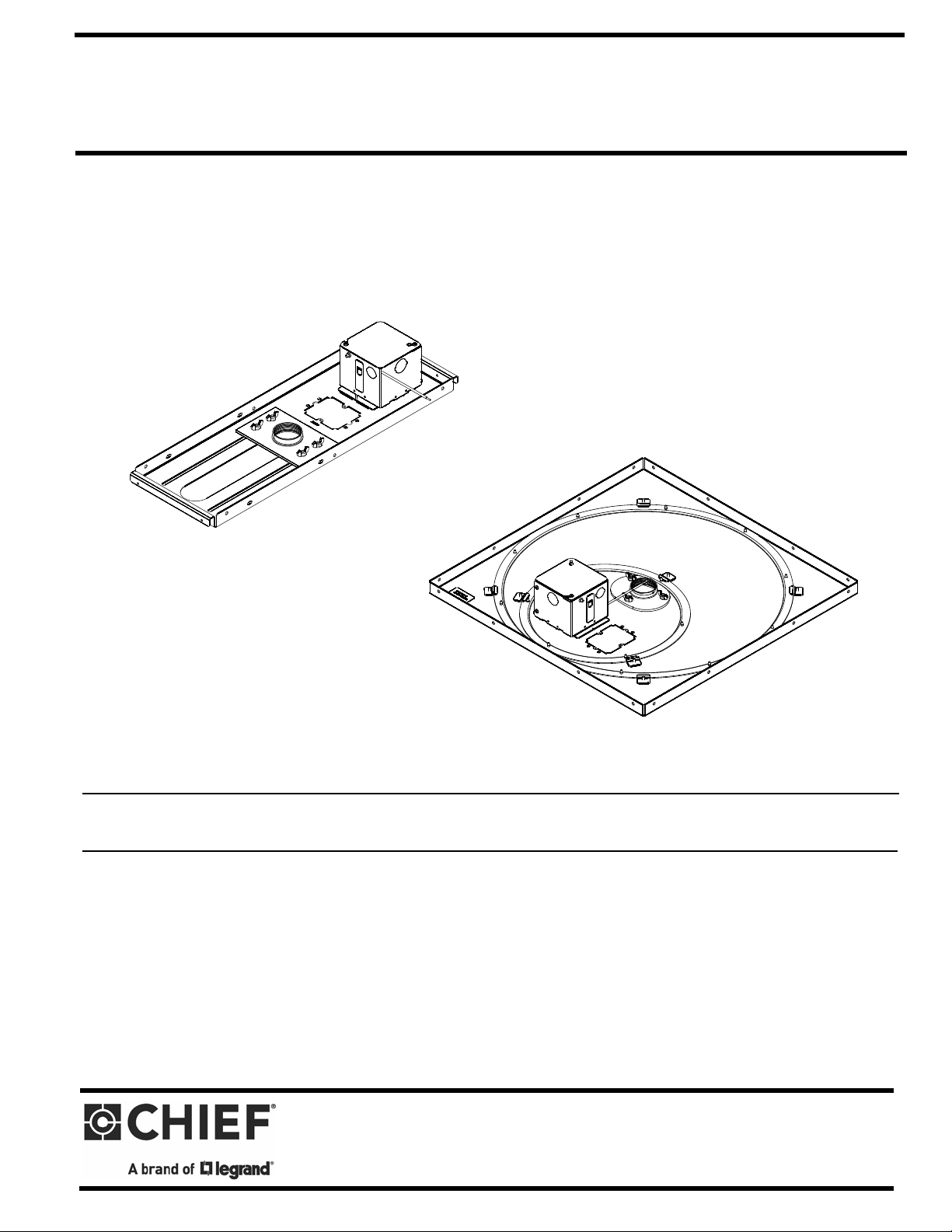
CMS440N
CMS445N
Above-Tile and Ceiling Tile Kits
Spanish Product Description
German Product Description
Portuguese Product Description
Italian Product Description
Dutch Product Description
French Product Description
CMS440N / CMS445N
ADDENDUM
Page 2

CMS440N / CMS445N Installation Instructions
Tighten Fastener
Apretar elemento de fijación
Befestigungsteil festziehen
Apertar fixador
Serrare il fissaggio
Bevestiging vastdraaien
Serrez les fixations
Loosen Fastener
Aflojar elemento de fijación
Befestigungsteil lösen
Desapertar fixador
Allentare il fissaggio
Bevestiging losdraaien
Desserrez les fixations
Pencil Mark
Marcar con lápiz
Stiftmarkierung
Marcar com lápis
Segno a matita
Potloodmerkteken
Marquage au crayon
Phillips Screwdriver
Destornillador Phillips
Kreuzschlitzschraubendreher
Chave de fendas Phillips
Cacciavite a stella
Kruiskopschroevendraaier
Tournevis à pointe cruciforme
A (1)
6-32 x 1/2"
10-32 x 3/8"
#10
Earthing symbol IEC 60418 No. 5019
affixed adjacent to grounding terminal.
(See Figures 3 and 7)
Grounding screw and washer installed at factory
DISCLAIMER
Legrand | AV and its affiliated corporations and subsidiaries
(collectively “Legrand | AV”), intend to make this manual
accurate and complete. However, Legrand | AV makes no claim
that the information contained herein covers all details,
conditions or variations, nor does it provide for every possible
contingency in connection with the installation or use of this
product. The information contained in this document is subject
to change without notice or obligation of any kind. Legrand | AV
makes no representation of warranty, expressed or implied,
regarding the information contained herein. Legrand | AV
assumes no responsibility for accuracy, completeness or
sufficiency of the information contained in this document.
Chief® is a registered trademark of Legrand AV Inc.
LEGEND
TOOLS REQUIRED FOR INSTALLATION / ADDITIONAL PARTS
2
Page 3

Installation Instructions CMS440N / CMS445N
Cut opening in ceiling
1
tile around outlet side
of electrical box.
3
x 2
Electrical box
cover
4
Grounding Lug Location
Green Grounding
Wire
6
7
x 2
WARNING: IMPROPER INSTALLATION CAN RESULT IN
DEATH OR SERIOUS PERSONAL INJURY! This accessory
should be installed by qualified personnel.
IMPORTANT ! : In addition to the CMS440 and CMS445
installation instructions accompanying the products, the
following steps must also be taken when installing the
CMS440N and CMS445N.
A 15 Amp duplex outlet (not included) may be installed into the
CMS440N and CMS445N, and the CMS440/445N must then be
connected to a 15 Amp branch circuit.
CMS440N
1. Cut a hole in the ceiling tile around the outlet side of the
electrical box so that the ceiling tile will fit over the
CMS440N. (See Figure 1)
WARNING: IMPROPER WIRING CAN LEAD TO DEATH
OR SEVERE PERSONAL INJURY! Grounding must be
installed by qualified personnel using a UL Recognized No.
12AWG Green grounding wire connected to grounding lug on
box.
WARNING: ELECTRICAL SHOCK HAZARD! Turn off
power to device before performing service.
Figure 3
5. Wire the CMS440N as required.
Figure 1
2. Install a 15 Amp duplex outlet (not included) into the
electrical box.
3. Loosen two Phillips head screws on the electrical box.
4. Remove electrical box cover. (See Figure 2)
6. Replace the electrical box cover. (See Figure 4)
7. Tighten two Phillips head screws in electrical box cover.
Figure 2
Figure 4
3
Page 4

CMS440N / CMS445N Installation Instructions
8
(A) x 1
Face plate
(not included)
2
x 2
Electrical box
cover
3
Grounding Lug Location
Green Grounding
Wire
6
x 2
Electrical box
cover
5
8. Attach face plate (not included) using one 6-32 x 1/2"
Phillips flat head screw (A) after the CMS440N has been
installed. (See Figure 5)
WARNING: ELECTRICAL SHOCK HAZARD! Turn off
power to device before performing service.
Figure 5
4. Wire the CMS445N as required.
CMS445N
1. Install a 15 Amp duplex outlet (not included) into the
electrical box.
2. Loosen two Phillips head screws on the electrical box.
3. Remove electrical box cover. (See Figure 6)
5. Replace the electrical box cover. (See Figure 8)
6. Tighten two Phillips head screws in electrical box cover.
Figure 7
Figure 8
Figure 6
WARNING: IMPROPER WIRING CAN LEAD TO DEATH
OR SEVERE PERSONAL INJURY! Grounding must be
installed by qualified personnel using a UL Recognized No.
12AWG Green grounding wire connected to grounding lug on
box.
4
Page 5

Installation Instructions CMS440N / CMS445N
7
(A) x 1
Face plate
(not included)
7. Attach face plate (not included) using one 6-32 x 1/2"
Phillips flat head screw (A) after the CMS445N has been
installed. (See Figure 9)
Figure 9
5
Page 6

CMS440N / CMS445N Installation Instructions
8800-003082 Rev00
2019 Legrand | AV
www.legrandav.com
12/19
USA/International A 6436 City West Parkway, Eden Prairie, MN 55344
P 800.582.6480 / 952.225.6000
F 877.894.6918 / 952.894.6918
Europe A Franklinstraat 14, 6003 DK Weert, Netherlands
P +31 (0) 495 580 852
F +31 (0) 495 580 845
Asia Pacific A Office No. 918 on 9/F, Shatin Galleria
18-24 Shan Mei Street
Fotan, Shatin, Hong Kong
P 852 2145 4099
F 852 2145 4477
 Loading...