

Page 1

INSTALLATION INSTRUCTIONS
ôtÉÉàñ
qÉprz
éts
wàêIQZaYîprIèàíértR
qÉprz
Сакай
ÉpÑâ
êàIátíêépÉ
rаССаб
véàíás
véttá
FAN SPEED & DUAL DIMMER/
FAN SPEED CONTROLS
R E A D A N D S A V E T H E S E I N S T R U C T I O N S !
To be installed by a certified electrician or other qualified person.
WARNING – Toprevent severe shock or electrocution,alwaysturn powerOFFat the
service panel before installing this unit,working onthecircuit, or changingalamp.
CAUTION – To reduce the risk of overheating and possible damage to other
equipment, do not install to control a receptacle, a fluorescent light, or a
transformer-supplied appliance. Use this control only with fans that are marked
as suitable for use with solid-state fan speed controls.
Any number of fans may be controlled by a single fan speed control provided
the sum amperage rating of the fans does not exceed the amperage rating of
the fan control.
Do not connect fan control to power source other than 120VAC, 60 Hz only.
Use copper wire only.
FOR DUAL DIMMER/FAN SPEED CONTROL – It is necessary to add the
required third wire from the wall box switching location to the fan with the light
kit unit. This is because the fan and light kit are essentially two separate units.
CAUTION – The additional third wire required should not be confused with the
neutral wire, usually WHITE, nor the ground wire, normally GREEN, which
may already be routed through the wall box. Warranty is void when any of the
three wires are attached to the neutral wire or ground wire. This will cause a
direct short and damage the controlʼs circuitry beyond repair.
Use copper wire only.
DIRECTIONS
1. Disconnect power to circuit at the panel by removing fuse or turning circuit
breakers OFF before installing.
2. Remove wall plate and switch mounting screws, pull existing switch from
wall box.
3. Disconnect existing switch from circuit.
4. Connect fan speed control as shown in the installation diagram with wire
connectors provided.
5. Install speed control device in wall box, using mounting screws provided.
Restore power to the circuit.
6. If fan has a multi-speed switch, place switch in the MAXIMUM SPEED
position, then do not change the switch setting.
7. To adjust Anti-Stall feature (if equipped): Set the fan speed control to lowest
speed and turn the power off. To change the minimum speed, adjust the
trimpot through the access opening in the front of the fan speed control,
using a small, insulated, flat-tipped screwdriver.
8. Attach wall plate.
NOTE: A 0.5A minimum load is required. It is normal for the control to feel
warm during operation. Use a separate neutral wire for each phase of a
multiphase system containing a dimmer, and for high power single phase
applications where flickering is present.
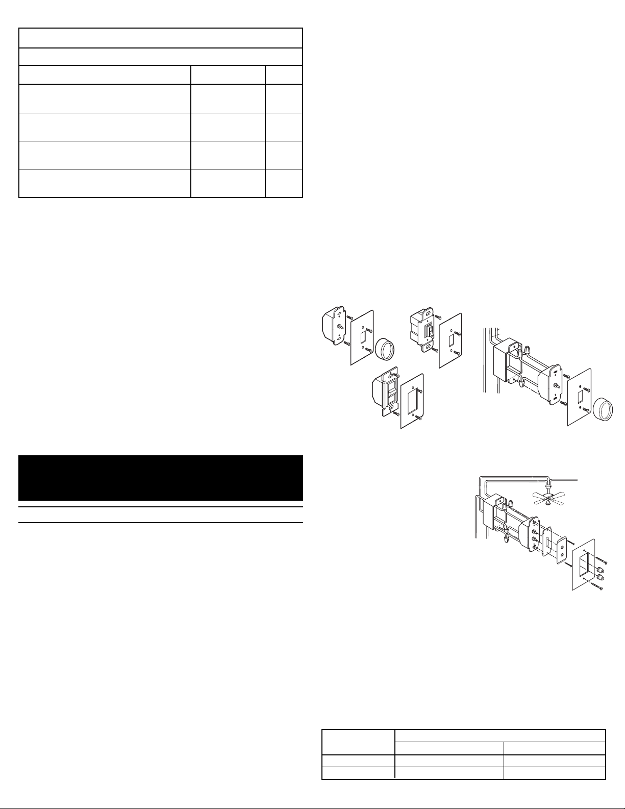
INSTALLATION DIAGRAM FOR SPEED CONTROLS (wiring is same with
each of the fan speed control types)
Rotary
Toggle
INSTALLATION DIAGRAM FOR DUAL DIMMER/FAN SPEED CONTROL
Identify fan/light kit wires. See fan/light
kit instructions (supplied by fan/light kit
manufacturer).
• Connect YELLOW wire from the
co n t rol to light kit lead
(incandescent only) with provided
wire connector.
• Connect RED wire from the control
to fan/mo t or le a d with provi d ed wir e
connector.
• Connect BLACK wire from control to 120VAC hot wire with
provided wire connector.
• Connect GREEN (or uninsulated) wire from control to ground wire
or metal wall box with provided wire connector.
MULTIPLE GANGING OF CONTROLS
Any combination of fan control models may be ganged together. Using vise or
heavy-duty pliers, remove the outer fins on either or both sides, as necessary,
at the break-off points on the thin metal line at the base of the third fin. Fan
controls can be ganged without removing fins by proper selection and
placement of outlet boxes. When fins are removed, de-rate the maximum load
according to the following De-Rating Table:
MAXIMUM
RATED LOAD
ONE SIDE TWO SIDES
FINS REMOVED
8 AMPS 7 AMPS 6 AMPS
12 AMPS 11 AMPS 10 AMPS
CAUTION : Sharp or jagged metal edges might be exposed where sections
were broken off. Use care when handling the control after this operation.
ILLUSTRATION FOR GANGING
Double-Gang Mixed Combination-Gang Fin Break-Off Points
HOW TO CUT PLASTIC FACEPLATE:
If fins are removed for ganging, the faceplate must be adjusted to match.
You may either score the groove on the back of the faceplate thoroughly with a
razor sharp packing knife, or you may partially score the groove, then
complete the break with pliers.
TO CUT THE FACEPLATE WITH KNIFE ONLY:
1. Lay faceplate face down on soft clean cloth,
on a flat solid surface to preserve finish.
2. Run knife vertically throughout groove
repeatedly until plastic separates.
3. Dress rough edges using very fine-grained
sand paper.
TO CUT THE FACEPLATE USING PLIERS AND KNIFE:
1. Lay faceplate face down on soft clean cloth, on a flat solid surface to
preserve finish.
2. Run knife vertically throughout groove
several times.
3. Hold faceplate firmly in one hand and
use pliers to bend the flat edge of the
fin away from the groove. Behind the
opposing ends first, then make a final
break at the middle, separating fin from
faceplate.
4. Dress rough edges using very fine-grained sand paper.
Slide
Page 2
átvéà
átvéà
qÉpárà
átíêépÉ
pIêxtéép
îtést
pIuнtбкtIstIZaYо
pIСакай
WIRE NUT USAGE CHART
pÑpéxÉÉà
átvéà
éàyà
pIuítáêtIstIZaYî
átvéà
pIСакай
ÉÁÑâpép
pIátíêépÉ
ràÑÚá
pIêxtéép
îtést
Use Only Copper Wire With This Device
Wire Combinations Strips Lengths Color
1#14 & 1#16; 1#14 & 2#18; 2,3#16; 1#16 & 1-3#18; 1/2" Except 9/16" Orange
3-5#18; 2#18 For #16 & #18 AWG
1#10 & 1#14; 1#12 & 1#14 2,3#14; 2#14 &1,2#16; 1/2" Except 5/8" Yellow
2#14 & 2,3#18;1#14 & 1-4#16; 1#14 & 1-4#18 For #18 AWG
1#10 & 1,2#12; 1#10 & 1-3#14; 2,3#12; 1#12 & 7/16" Except 1/2" Red
1-3#14; 1#12 & 3#16; 3,4#14 For #16
1#14 & 1,2#16; 1#14 & 1,2#18; 2,3#16; 2-5#18 7/16" For #14 & #16 Ivory
1/2" For #18
WARRANTIES
Lifetime Warranty. The device you have purchased is warranted under normal
use against defects in workmanship and materials for as long as you own the
device. If the device fails due to manufacturing defect during normal use, return
the device for replacement to the store where purchased or send to:
Pass & Seymour Legrand
50 Boyd Avenue
Syracuse, NY 13209
All requests for replacement must include a dated sales receipt (legible copies
acceptable).
ALL OTHER WARRANTIES, INCLUDING BUT NOT LIMITED TO ANY
WARRANTIES OF MERCHANTABILITY OR FITNESS FOR A PARTICULAR
PURPOSE, ARE LIMITED TO A PERIOD OF TWO YEARS FROM THE DATE
OF PURCHASE. YOUR SOLE AND EXCLUSIVE REMEDY AGAINST PASS &
SE Y M OUR LE G R AND UN D E R ANY WARRANT Y SHAL L BE THE
EQUIVALENT REPLACEMENT OF THE DEVICE. IN NO EVENT SHALL ANY
WARRANTY APPLY TO ANY DEFECT ARISING OUT OF ANY ALTERATION
OF THE DEVICE, IMPROPER WIRING, IMPROPE R INSTALLATION,
MISUSE, ABNORMAL USE OR NEGLIGENCE. IN NO EVENT SHALL PASS
& SEYMOUR LEGRAND BE LIABLE FOR LOST PROFITS, INDIRECT,
SPECIAL, EXEMPLARY, INCIDENTAL OR CONSEQUENTIAL DAMAGES.
Some states do not allow limitations on how long implied warranties last and
do not allow exclusion or limitation of incidental or consequential damages.
Some of the above limitations or exclusions may not apply to every purchaser.
INSTRUCCIONES EN ESPAÑOL
INSTRUCCIONES DE INSTALACIÓN
MANDO DE VELOCIDAD DE VENTILADOR Y DOBLE MANDO
DE VELOCIDAD DE VENTILADOR/REDUCTOR DE LUZ
L E A Y G U A R D E E S T A S I N S T R U C C I O N E S
Para ser instalado por electricista certificado u otra persona capacitada.
ADVERTENCIA: Para prevenir una sacudida eléctrica severa o
electrocución, siempre CORTE la electricidad en el panel de servicio antes de
instalar esta unidad, trabajar en el circuito, o cambiar una lámpara.
AVISO: Para reducir el riesgo de recalentamiento y posiblemente dañar a
otro equipo, no instale para controlar un receptáculo, una luz fluorescente, un
artefacto alimentado por un transformador. Use este mando solo con
ventiladores que indican que son apropiados para uso con mandos de
velocidad de ventiladores de estado sólido.
Cualquier número de ventiladores pueden ser controlados por un solo mando
de velocidad de ventiladores dado que la suma de las tasas de amperaje de
los ventiladores no exija la tasa de amperaje del mando del ventilador.
No conecte al reductor de luz a otra fuente de potencia que no sea solo
120VAC, 60Hz.
Solo utilice cables de cobre.
PARA DOBLE MANDO DE VELOCIDAD DE VENTILADOR/REDUCTOR DE
LUZ: Es necesario agregar el tercer cable requerido desde el sitio de mando
de la caja embutida en la pared hasta el ventilador con la unidad del equipo de
la luz. Esto tiene que ser porque el ventilador y la luz son esencialmente dos
unidades separadas. AVISO: Eltercercableadicionalnosedebe confundirconel
cableneutral,normalmenteBLANCO,ni con el cable que hacetierra, normalmente
VERDE, el cualpuede que ya haya sido corrido por la caja embutida en la pared.
La garantía se invalida cuando cualquieradeestostrescables están conectadosal
cableneutralo alcable quehace tierra. Esto causará un corte directo y dañará los
circuitos del mando sin remedio.
Solo utilice cables de cobre.
INSTRUCCIONES:
1. Corte la electricidad al circuito en el panel quitando el fusible o APAGANDO
el interruptor automático antes de la instalación.
2. Quite la chapa de pared y los tornillos de montura de chucho, hale el
chucho existente de la caja embutida en la pared.
3. Desconecte el chucho existente del circuito.
4. Conecte el mando de velocidad de ventilador como es demostrado en el
esquema de instalación con los conectores de cables suministrados.
5. Instale al aparato de mando de velocidad en la caja embutida en la pared,
utilizando los tornillos de montura suministrados. Vuelva a conectar la
electricidad al circuito.
6. Si el ventilador tiene un chucho de velocidades múltiples, ponga el chucho
en la posición de VELOCIDAD MÁXIMA, y después no cambie la posición
de chucho.
7. Para ajustar la característica de Anti - Parada (si provisto): Ajuste el mando
de velocidad del ventilador a la velocidad más baja y corte la electricidad.
Para cambiar la velocidad mínima, cambie el ajuste fino por medio de la
abertura de acceso en el frente del mando de velocidad de ventilador,
usando un destornillador plano, aislado, pequeño.
8. Conecte la chapa de pared.
NOTA: Una carga mínima de 0.5A es requerida. Es normal que el mando se
sienta caliente durante su funcionamiento. Use un cable separado neutral
para cada fase de un sistema polifásico que tiene un reductor de luz, y para
aplicaciones de una fase de alta potencia donde ocurre centelleo.
ESQUEMA DE INSTALACIÓN PARA MANDOS DE VELOCIDAD
(El alambrado es el mismo con cada uno de los tipos de mandos de velocidad
de ventilador.)
Rotatoria
Corredera
Interruptor
ESQUEMA DE INSTALACIÓN PARA DOBLE MANDO DE VELOCIDAD DE
VENTILADOR/REDUCTOR DE LUZ
Identifique los cables del equipo de
ventilador/luz. Vea las instrucciones del
equipo de ventilador/luz (suministrado
por el fabricador del equipo de
luz/ventilador).
• Conecte al cable AMARILLO del
mando al conductor del equipo de luz
(solo incandescente) con el conector
de cable suministrado.
• Conecte al cable ROJO del mando al conductor
del ventilador/motor con el conector del cable
suministrado.
• Conecte al cable NEGRO del mando al cable cargado de
120VAC con el conector de cable suministrado.
• Conecte al cable VERDE (o el cable no aislado) del mando al cable que
hace tierra o a la caja de metal embutida en la pared con el conector de
cable suministrado.
AGRUPACIÓN MÚLTIPLE DE MANDOS
Cualquier combinación de modelos de mandos de ventilador pueden ser
agrupados juntos. Usando una prensa de tornillo o una pinza de servicio
pesado, quite las aletas exteriores en cualquier de los dos lados o en los dos
lados, como sea necesario, en los puntos de abertura en la línea de metal fina
en la base de la tercera aleta. Mandos de ventilador pueden ser agrupados sin
quitar a las aletas por medio de la selección y colocación apropiada de las
cajas de salida. Cuando se han quitado las aletas, reajuste el cargo máximo
según el Cuadro de Reajuste siguiente:
CARGA
MÁXIMA TAZADA
UN LADO DOS LADOS
ALETAS ELIMINADAS
8 AMPS 7 AMPS 6 AMPS
12 AMPS 11 AMPS 10 AMPS
Page 3

AVISO: Bordes de metal afilados o dentados pueden ser expuestos donde se
han partido secciones. Mantenga cuidado cuando este manejando el mando
después de esta operación.
ESQUEMA PARA AGRUPACIÓN
ALTERACIÓN DEL APARATO, CABLEADO IMPROPIO, INSTALACIÓN
IMPROPIA, MAL USO, USO ANORMAL O NEGLIGENCIA. BAJO NINGÚN
CASO, SERÁ RESPONSABLE PASS AND SEYMOUR LEGRAND DE DAÑOS
POR PÉRDIDAS EN INGRESOS, INDIRECTOS, ESPECIALES, EJEMPLARES,
INCIDENTALES, O CONSECUENTES.
Algunos estados no permiten limitaciones en la duración de las garantías
implícitas y no permiten exclusión o limitación de daños accidentales o
consecuentes. Algunas de las limitaciones o exclusiones arriba enunciadas
podrán no ser aplicadas a cada comprador.
Agrupación
Doble
Agrupación
De Combinación Mixta
Puntos De Abertura
De Las Aletas
COMO CORTAR LA PLACA DE RECUBRIMIENTO DE PLÁSTICO:
Sinlas aletas se han quitadoparaagrupación, la placa de recubrimientotiene que ser
ajustado para que coincida. Usted puede o rayar a fondo la ranura la parte de
atrás de la placa de recubrimiento con una cuchilla de empaquetar que esté bien
afilada, o puede rayar la ranura parcialmente, y completar la quiebra con pinzas.
PARA CORTAR LA PLACA DE RECUBRIMIENTO CON SOLO UNA
CUCHILLA:
1. Acueste a la placa de recubrimiento mirando hacia abajo sobre una tela
suave y limpia, sobre una superficie sólida y plana para preservar la
terminación.
2. Corra la cuchilla verticalmente a través de la
ranura varias veces hasta que se separe el
plástico.
3. Lije los bordes ásperos con papel de lija de
grano fino.
PARA CORTAR LA PLACA DE RECUBRIMIENTO USANDO UNA
CUCHILLA Y PINZAS:
1. Acueste a la placa de recubrimiento mirando hacia abajo sobre una tela
suave y limpia, sobre una superficie
sólida y plana para preservar la
terminación.
2. Corra la cuchilla verticalmente a través
de la ranura varias veces.
3. Aguante a la placa de recubrimiento firmemente en una mano y use pinzas
para doblar el borde plano de la aleta alejándola de la ranura. De tras de
las puntas opuestas primero, luego haga una partida final en el medio,
separando a la aleta de la placa de recubrimiento.
4. Lije los bordes ásperos con papel de lija de grano fino.
CUADRO DE USO DE TUERCA DE CABLES
Use Cable De Cobre Nadamás Con Este Aparato
Combinaciones De Cables Longitudes De Tiras Color
1#14 & 1#16; 1#14 & 2#18; 2,3#16; 1#16 & 1-3#18; 1/2" Except 9/16" Naranja
3-5#18; 2#18 For #16 & #18 AWG
1#10 & 1#14; 1#12 & 1#14 2,3#14; 2#14 &1,2#16; 1/2" Except 5/8" Amarillo
2#14 & 2,3#18;1#14 & 1-4#16; 1#14 & 1-4#18 For #18 AWG
1#10 & 1,2#12; 1#10 & 1-3#14; 2,3#12; 1#12 & 7/16" Except 1/2" Rojo
1-3#14; 1#12 & 3#16; 3,4#14 For #16
1#14 & 1,2#16; 1#14 & 1,2#18; 2,3#16; 2-5#18 7/16" For #14 & #16 Marfil
1/2" For #18
GARANTÍAS
Garantías de Por Vida: El aparato que Ud. ha comprado está garantizado
bajo uso normal contra de defectos de fábrica y materiales durante el tiempo
que Ud. posea el aparato. Si el aparato falla debido a defectos de fábrica
durante uso normal, devuelva el aparato para su reemplazo a la tienda donde
fue adquirido o envíelo a: Pass & Seymour Legrand, 50 Boyd Avenue,
Syracuse, NY 13209
Todos los pedidos de reemplazos deben incluir un recibo de compra fechado (se
aceptan copias legibles). TODAS LAS DEMÁS GARANTÍAS INCLUIDAS PERO
NO LIMITADAS A CUALQUIER GARAN TÍA COMERCIAL O DE
PARTICULARIDAD PARA UN PROPÓSITO ADECUADO, ESTÁN LIMITADAS A
UN PERÍODO DE DOS AÑOS A PARTIR DE LA FECHA DE COMPRA. SU
ÚNICO Y EXCLUSIVO DERECHO CON RESPECTO A PASS AND SEYMOUR
LEGRAND BAJO CUALQUIER GARANTÍA SERÁ EL REEMPLAZO POR UN
APARATO EQUIVALENTE. EN NINGÚN CASO, NINGUNA GARANTÍA PODRÁ
SER APLICADA A NINGÚN DEFECTO QUE SURJA DE NINGUNA
INSTRUCTIONS EN FRANÇAIS
INSTRUCTIONS DʼINSTALLATION
DISPOSITIFS DE CONTROLE DE VITESSE DE
VENTILATEUR ET ENSEMBLE VARIATEUR/
VITESSE DE VENTILATEUR
L I R E E T C O N S E R V E R C E S I N S T R U C T I O N S
Doit être installé par un électricien certifié ou autre personne qualifiée.
AVERTISSEMENT: Pour éviter une décharge grave ou une électrocution,
toujours couper le courant au tableau de service avant dʼinstaller cette unité,
de travailler sur le circuit ou de changer une lampe.
ATTENTION: Pour réduire les risques de surchauffe et tout dommage à
dʼautres équipements, ne pas installer pour contrôler une prise électrique, une
lampe fluorescente, ou un appareil muni dʼun transformateur. Utiliser ce
dispositif de contrôler seulement avec des ventilateurs sur lesquels il est
indiqué quʼils sont compatibles avec des dispositifs de contrôle de vitesse de
ventilateur à semi-conducteurs. Plusieurs ventilateurs peuvent être contrôlés
par un seul dispositif de contrôle de vitesse de ventilateur tant que la somme
des intensités nominales des ventilateurs ne dépasse pas lʼintensité nominale
du dispositif de contrôle de ventilateur.
Ne pas connecter le dispositif de contrôle de ventilateur pour alimenter une
source autre que 120 VAC, 60 Hz uniquement.
Utiliser des fils en cuivre uniquement.
POUR LʼENSEMBLE DE CONTROLE VARIATEUR/VITESSE DE
VENTILATEUR: Avec une unité kit lampe, il est nécessaire dʼajouter le
troisième fil indispensable depuis lʼemplacement de commutation dans le
coffret mural jusquʼau ventilateur. Cela est nécessaire car le ventilateur et le kit
lampe sont essentiellement deux unités séeparées. ATTENTION: Le troisième
fil supplémentaire indispensable ne doit pas être confondu avec le fil neutre,
habituellement BLANC, ni le fil de terre, habituellement VERT, qui peuvent
déja être montés dans le coffret mural. La garantie est annulée si lʼun
quelconque des trois fils est attaché au fil neutre ou au fil de terre. Cela résulte
en un court cicuit direct et endommage le circuit du dispositif de contrôle au
delà de toute réparation.
Utiliser des fils en cuivre uniquement.
INSTRUCTIONS:
1. Couper lʼalimentation du circuit au tableau en enlevant le fusible ou en
mettant lʼinterrupteur en position ARRET avant installation.
2. Enlever la plaque murale et les vis de montage de lʼinterrupteur, retirer
lʼinterrupteur existant du coffret mural.
3. Déconnecter lʼinterrupteur existant du circuit.
4. Connecter le dispositif de contrôle de vitesse de ventilateur comme indiqué
sur le schéma dʼinstallation avec les fils de branchement fournis.
5. Installer le dispositif de contrôle de vitesse dans le coffret mural, en utilisant
les vis de montages fournies. Restaurer lʼalimentation du circuit.
6. Si le ventilateur a un interrupteur à vitesse multiple, placer lʼinterrupteur
dans la position VITESSE MAXIMALE, puis ne plus le changer de position.
7. Pour ajuster le dispositif Anti-Callage (sʼil y en a un): Régler le dispositif de
contrôle de vitesse de ventilateur à la vitesse la plus basse et éteindre le
ventilateur. Pour changer la vitesse minimale, ajuster le bouton de réglage
à travers lʼouverture dʼaccès devant le dispositif de contrôle de vitesse du
ventilateur, en utilisant un petit tourne-vis isolé a bout plat.
8. Mettre en place la plaque murale.
REMARQUE: Une charge minimale de 0.5 A est requise. Il est normal que le
dispositif de contrôle sʼéchauffe lorsquʼil fonctionne. Utiliser un fil neutre
séparé pour chaque phase dʼun système multiphasé contenant un variateur, et
pour les applications haute puissance à une seule phase en cas de
vacillement.
Page 4

SCHEMA DʼINSTALLATION POUR LES DISPOSITIFS DE CONTROLE
áàxé
áàxé
qÉpár
átíêét
pIÉpIêtéét
îtéê
pIÉpIèàíértIZaYIî
píIÑàêtíé
ypíát
áàxé
éàívt
pIÉpIèàíértIZaYIî
áàxé
Ñàêtíé
ÉpÑât
píIátíêét
rаССнб
pIÉpIêtéét
îtéê
DE VITESSE
(Lʼinstallation électrique est la même pour tous les types de dispositif de
contrôle de vitesse de ventilateurs.)
Rotatif
A Coulisse
A Basculeur
SCHEMA DʼINSTALLATION POUR LʼENSEMBLE DE CONTROLE
VARIATEUR/VITESSE DE VENTILATEUR
Identifier les fils du kit ventilateur/lampe.
Lire les instructions du kit ventilateur/
lampe (fournies par le fabricant du kit
ventilateur/lampe).
• Connecter le fil JAUNE du dispositif de
contrôle au fil de lampe du kit
(incandescent seulement) avec le fil
de branchement fourni.
• Connecter le fil ROUGE du dispositif de contrôle au fil
ventilateur/moteur avec le fil de branchement fourni.
• Connecter le fil NOIR du dispositif de contrôle au fil de
couleur vive 120 VAC avec le fil de branchement fourni.
• Connecter le fil VERT (ou non isolé) du dispositif de contrôle au fil
de terre ou au coffret mural métallique avec le fil de branchement fourni.
DISPOSITIF DE CONTROLE MULTIPLE EN SERIE
Toute combinaison de modèles de dispositif de contrôle de vitesse de
ventilateur peut être mise en série. A lʼaide dʼun étau ou dʼune pince solide,
enlever les ailettes extérieures dʼun côté ou des deux, si nécessaire, aux
endroits de cassure sur la ligne métallique fine à la base de la troisième
ailette. Les dispositif de contrôle de ventilateur peuvent être raccordés en série
sans enlever les ailettes en selectionnant et plaçant correctement les boîtiers
de sortie. Quand les ailettes sont retirées, réduire la charge maximale en
fonction du tableau de Dé-Classement suivant:
CHARGE NOMINALE
MAXIMALE
AILETTES RETIREES
UN COTE DEUX COTES
8 AMPS 7 AMPS 6 AMPS
12 AMPS 11 AMPS 10 AMPS
ATTENTION: Des arêtes pointues ou irrégulières risquent dʼêtre exposées
aux endroits où les éléments ont été cassés. Manipuler le dispositif de contrôle
avec précaution après cette opération.
ILLUSTRATION POUR MISE EN SERIE
POUR DECOUPER LA PLAQUE FRONTALE AVEC UNE PINCE ET UN
COUTEAU:
1. Placer la plaque frontale face en bas sur
un tissu doux et propre, sur une surface
plate pour protéger la finition.
2. Déplacer le couteau verticalement
plusieurs fois.
3. Tenir la plaque frontale fermement dʼune main et utiliser une pince pour
plier et détacher de la rainure le côté plat de lʼailette. Dʼabord derrière les
deux côtés opposés, puis terminer la cassure au centre, séparant lʼailette
de la plaque frontale.
4. Polir les bords irréguliers avec du papier de verre très fin.
TABLEAU DʼUTILISATION DES ECROUS DE CABLAGE
Utiliser Uniquement Des Fils En Cuivre Avec Cet Appareil
Combinaisons De Fils Longueurs Denudees Couleur
1#14 & 1#16; 1#14 & 2#18; 2,3#16; 1#16 & 1-3#18; 1/2" Except 9/16" Orange
3-5#18; 2#18 For #16 & #18 AWG
1#10 & 1#14; 1#12 & 1#14 2,3#14; 2#14 &1,2#16; 1/2" Except 5/8" Jaune
2#14 & 2,3#18;1#14 & 1-4#16; 1#14 & 1-4#18 For #18 AWG
1#10 & 1,2#12; 1#10 & 1-3#14; 2,3#12; 1#12 & 7/16" Except 1/2" Rouge
1-3#14; 1#12 & 3#16; 3,4#14 For #16
1#14 & 1,2#16; 1#14 & 1,2#18; 2,3#16; 2-5#18 7/16" For #14 & #16
Ivoire
1/2" For #18
GARANTIES
Garantie à vie. Lʼappareil que vous venez dʼacheter est garanti, sous condition
dʼutilisation normale, contre tout défaut dans la fabrication et les matériaux tant
quʼil est en votre possession. Si cet appareil tombe en panne à cause de
défauts de fabrication pendant son utilisation normale, le rapporter pour quʼil
soit remplacé, le cas échéant, là où vous lʼavez acheté ou lʼenvoyer à: Pass &
Seymour Legrand, 50 Boyd Avenue, Syracuse, NY 13209
Toute demande de remplacement doit contenir un reçu de vente (photocopies
lisibles acceptées).
TOUTES AUTRES GARANTIES, Y COMPRIS MAIS NON LIMITEES A TOUTE
GARANTIE DE COMMERCIALISATION OU APTITUDE A SATISFAIRE UNE
FONCTION PARTICULIERE, SONT LIMITEES A UNE PERIODE DE DEUX
ANS A COMPTER DE LA DATE DʼACHAT. VOTRE RECOURS UNIQUE ET
EX CLUSIF C ONTRE PAS S & SEYMOUR L EGRAND S OUS TOUTE
GARANTIE EST LE REMPLACEMENT EQUIVALENT DE VOTRE APPAREIL.
EN AUCUN CAS LA GARANTIE NE SʼAPPLIQUE A DES DEFAUTS DE
FONCTIONNEMENT DUS A DES MODIFICATIONS DE LʼAPPAREIL, UN
CA BLAGE INCO RRECT, UN E INSTA LLATION INCOR RECTE, UNE
MAUVAISE UTILISATION, UNE UTILISATION ANORMALE OU DE LA
NEGLIGENCE. EN AUCUN CAS PASS & SEYMOUR LEGRAND NʼEST
RESPON SABLE PO UR U NE PERTE DE PROFIT, OU DES DEGATS
IN DIRECT S, PARTICUL I ERS, EXEMP LAIRES, MIN EURS OU
CONSEQUENTS. Certains états nʼautorisent pas de limite sur la durée des
garanties implicites et ne permettent pas dʼexclusion ou de limite quant aux
dégâts mineurs ou conséquents. Il se peut que certaines des limites ou
exclusions ci-dessus ne sʼappliquent pas à tous les acheteurs.
Serie Double Serie Combinaison Melangee Endroits De Cassure Des Ailettes
COMMENT DECOUPER LA PLAQUE FRONTALE DE PLASTIQUE:
Si les ailettes ont été enlevées pour un montage en série, la plaque frontale
doit être ajustée en conséquence.
Vous pouvez soit entailler la rainure au dos de la plaque frontale
complètement à lʼaide dʼun couteau bien aiguisé, soit entailler partiellement la
rainure, puis terminer la cassure avec une pince.
POUR DECOUPER LA PLAQUE FRONTALE AVEC UN COUTEAU
SEULEMENT:
1. Placer la plaque frontale face en bas sur un
tissu doux et propre, sur une surface plate
pour protéger la finition.
2. Déplacer le couteau verticalement plusieurs fois le
long de la rainure jusquʼà ce que le plastique se sépare.
3. Polir les bords irréguliers avec du papier de verre très fin.
Part No. 340407 Rev. B
Printed in U.S.A.
© 1997 Pass & Seymour/Legrand, P.O. Box 4822, Syracuse, NY 13221, (800) 223-4185
 Loading...