

Page 1
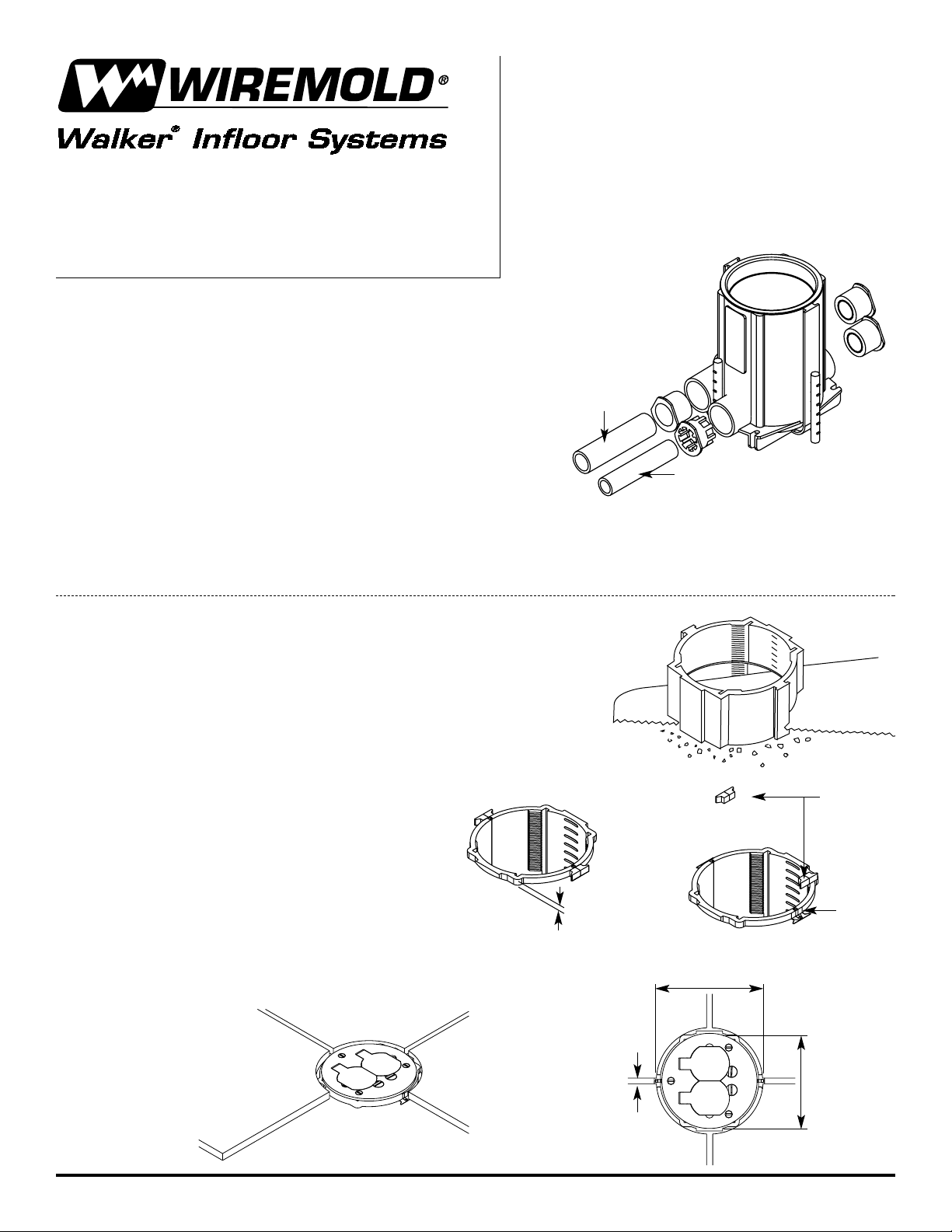
Before Pour:
1. Locate box position. Orientation of duplex
receptacle is aligned with the conduit.
2. Cement conduit closure plugs to unused ports and conduit
reducers if reduction from the 1" [25mm] hubs is required.
3. Secure box to grade or form using nails, screws,
rebar and wire or other appropriate means.
4. Cement conduit feed to hubs/reducers.
5. Pour concrete to required height (2 1/4" to 6 1/2" [57mm to 165mm]).
6. If used for dual service, use the center hubs for power and the outer hubs for low voltage.
After Concrete Sets:
1. Use a hand saw to cut the top of the box
extending above the floor surface (see Figure 1).
2. Tile: Cut must be square and parallel
with the floor surface for tile applications.
a. For 1/8" [3.2mm] thick tile, cut top
of box flush with concrete pour.
b. For 3/8" [9.5mm] thick tile, cut top
of box 1/4" [6.4mm] above concrete
pour (see Figure 2).
1. Cut away flanges at screed
level (see Figure 3).
2. Apply tile over concrete
floor (see Figure 4).
3. 1/4" [6.4mm] of grout
is required between tile
flange and tile (see Figure 5).
Ratchet-Pro
™
881 PVC Floor Box
895DCC Cover
INSTALLATION INSTRUCTIONS
Walker® electrical systems conform to and should
be properly grounded in compliance with requirements of the current National Electrical Code or
codes administered by local authorities.
All electrical products may present a possible
shock or fire hazard if improperly installed or
used. Walker electrical products may bear the
mark as UL Listed and/or Classified and should
be installed in conformance with current local
and/or the National Electrical Code.
Low Voltage
Power
4 1/4" [108mm]
Flange Diameter
Figure 1
Cut Edge
Figure 3
1/4" [6.4mm]
Above Concrete
Figure 2
4 3/4"
[121mm]
1/4" [6.4mm]
Clearance
Required
Between
Flange and Tile
Figure 4
Figure 5
Saw Away
These Sections
Page 2
After Concrete Sets Continued:
3. Carpet: If floor covering is greater than 5/16" [7.9mm] thick, allow additional amount of the box to project above
the floor to compensate. Example: For 3/8" [9.5mm] thick carpet and padding, subtract 5/16" [7.9mm]
from 3/8" [9.5mm] and allow an additional 1/16" [1.6mm] of the box to extend above the floor surface.
4. When Installing Cat. No 895DCC on Wood Floor Covering: Cut must be square and parallel with the floor
surface. Cut top of box flush with the concrete
pour. Using a hole saw, cut a 4 3/4" [121mm]
diameter hole in the wood floor covering
concentric with the opening in the top
of the floor box. Install cover as shown below.
NOTE: A template is recommended to assure a desirable fit with the cover for thicker floor coverings. Use a 5" [127mm] diameter hole saw and remove a core from
a steel or wood sheet with the same thickness as the required projection. Lay the template over the box and make cut flush with the template’s surface.
Activation – Single Service: Power/Low Voltage:
1. Use any Walker Systems 895 or 896 (brass or plastic activation).
2. Requires 881 Floor Box Adapter, Cat. No. 881ADP.
3. Wiring capacity is noted by the first legible marking visible
in the interior of the box.
4. Wire and fasten device (if required) and cover to adapter.
5. Push adapter and cover assembly into box opening – no glue required!
Activation – Dual Service:
Low Voltage Divider – Cat. No. 881DIV
1. Divider height is determined by the first legible letter visible
in the interior of the box.
2. Using a utility knife, score the groove in the divider just above
the corresponding letter and snap apart.
3. Wiring capacity of the box is reduced by the largest number
indicated at the bottom of the divider.
4. Slide the divider in set of grooves between the center
and outer hubs.
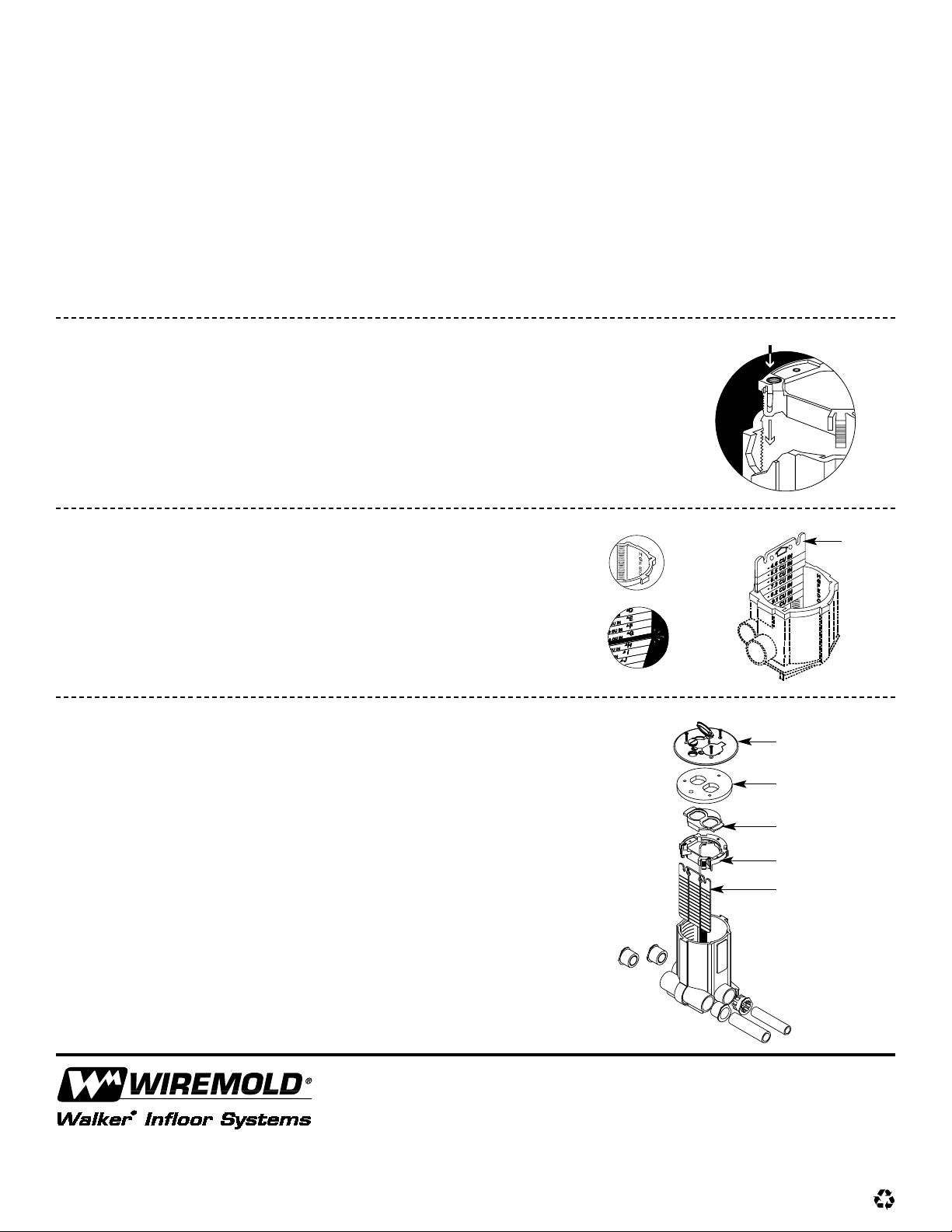
Activation Cover – Cat. No. 895DCC (For use on 881 Floor Box):
NOTE: This cover is UL Listed for use on carpet and wood covered floors only.
1. Wire and fasten device to adapter.
2. Place duplex support plate (supplied with
divider Cat. No. 881DIV) over receptacle.
3. Attach cover over adapter with three
#8-32 x 1/2" [12.7mm] screws.
4. Remove 1/2" [12.7mm] screw plug and
pull low voltage cables through opening.
5. Insert and push adapter and cover assembly
into box opening – no glue required!
Push Downward To Engage Teeth
Walker Systems, Inc.
U.S.
1000 Innovation Drive • Williamstown, WV 26187
1-800-240-2601 • FAX 800-254-5498 • Outside U.S.: 860-233-6251
Canada:
850 Gartshore Street • Fergus, Ontario N1M 2W8
1-800-741-7957 • FAX 519-843-5980
IA0171 1101
© Copyright 2001 The Wiremold Company All Rights Reserved
Cover
Divider
Scrub Water Gasket
Adapter
Divider
Duplex Support Plate
 Loading...