

Page 1
87045 LIMOGES Cedex
Telephone: (+33) 05 55 06 87 87 - Fax: (+33) 05 55 06 88 88
Configuration tool with screen
This parameter setting tool works in a system with detectors.
It is used to receive and send data via infra-red.
- set the detector parameters (Time delay, Daylight setpoint, etc.)
- configure stand-alone detectors from the brand and BUS detectors
belonging to a system
- adjust the system according to the characteristics of the installation
location
- save the Light regulation (maximum of up to 26 configuration files)
- duplicate other detectors (copy/paste a setting type)
- connect BUS products (Push & Learn)
2. TECHNICAL FEATURES
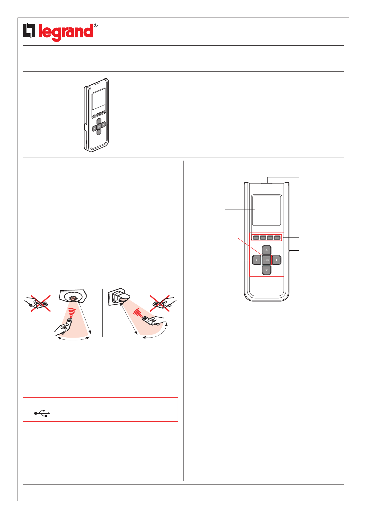
Infra-red communication technology (4 m max.)
In the direction of the product to be measured
At a +/- 15° angle limit in the axis of the PIR transmission and
reception LED (see image)
Cat. no(s).: 882 30
2. TECHNICAL CHARACTERISTICS (continued)1. USE
Display screen
On/Off and validation
Control and navigation
keys
CONTENTS Page
1. Use ............................1
2. Technical features ................1
3. Navigation ......................2
4. Standard EN12464-1
recommendations.................5
5. Maintenance.....................5
6. Standards .......................5
PIR transmission and
reception LED
Function access
keys
Mini-USB
connector
4 m4 m
+/- 15°
Backlight screen (automatic switch off)
Weight: 71 g
Impact resistance: IK04
Operating temperature: -5°C to +45°C
Storage temperature: -20°C to +70°C
RECHARGING: Use a mini USB cable (not supplied) for
recharging the configuration tool with a standard
USB socket.
Technical data sheet: F01163EN/00
Works with all factory pre-set compatible detectors (infra-red,
ultrasound or dual technology).
+/- 15°
The lux parameters adapt to the detector and installation type.
Updated on: Created on: 23/08/2010
CONTENTS
1/5
Page 2

Configuration tool with screen
Cat. no(s).: 882 30
3. NAVIGATION
3.1 Pictograms
Back to previous page
Takes the current detector configuration
Sends a configuration to the detector
Creation of a backup file
Provides the website address for the online technical
documents (www.legrandoc.com)
Deletes a file
Shows a file's parameters
del
Deletes a product from the configuration
learn
Adds a product to the configuration
The 4 buttons control the pictogram functions
displayed above
3. NAVIGATION (continued)
3.2 Instructions for use
ON
2-3 sec
3.2.1. Sensor parameters
1
2
3
4
5
6
Sensor parameters
Advanced mode
Files
PnL sensor
Files
PnL sensor
Test
Settings
Sensor parameters
1
Sensor parameter
Advanced mode
Files
PnL sensor
A
Time delay
000 H 15 Min 00 Sec
Max. time delay
255 H 59 Min 59 Sec
D
Auto on / off
Walkthrough
Manual on / Auto off
Partial on / Group off
Mode
W
Sensitivity
PIR
Very high < >
US High < >
Very high
High
Medium
Low
E
Detection scheme
Initial
PIR and US < >
Maintain PIR or US < >
Retrigger PIR or US < >
Time delay
Sensitivity
Daylight setpoint
Mode
Detection scheme
Alert
C
Max.: 1275 Lux
M
Audible
A
W
C
D
E
M
Daylight setpoint
0500 Lux
Alert
PIR and US
PIR or US
PIR only
US only
Technical data sheet: F01163EN/00 Updated on: Created on: 23/08/2010
CONTENTS
ON/OFF
Status change
"BEEP" on the
detector
2/5
Page 3

Configuration tool with screen
Cat. no(s).: 882 30
3. NAVIGATION (continued)
3.2 Instructions for use (continued)
3.2.1. Sensor parameters (continued)
A
Time delay
Length of time the load is on after a detection is made. See technical data sheet
for the associated detector.
B
Sensitivity
Setting the detector range (see technical data sheet for the associated detector).
C
Daylight setpoint
Value at which the load comes on if light is less than the Light regulation and
goes off if it is above this threshold. The Daylight setpoint can be set up to a
maximum of 1275 lux.
D
Mode
There are 4 different operating modes.
Auto on/Auto off mode:
Comes on automatically:
- At the detection of a presence if there is an insufficient natural level of light.
Turns off automatically:
- If no presence is detected and at the end of the time delay set.
- Or if there is a sufficient level of natural light (activated Light regulation).
Any new detection causes an automatic switch on if there is insufficient light.
Walkthrough:
- If there is no presence detected in the 3 minutes following an initial detection,
the detector will cut off after 3 minutes.
- If a new presence is detected in the 3 minutes following the initial detection, the
device will cut off at the end of the time delay set.
Manual on/Auto off mode:
Comes on via a manual switch, automatic switch off:
- Where no presence is detected and at the end of the time delay set.
Following switch off, any new detection within a 30-second period will cause the
device to be switched on automatically.
After 30 seconds the device is switched on via a manual switch.
Partial on/Group off mode:
This mode is used to ungroup circuits that are switched on upon detection and
the circuits which will be switched off at the end of the detection.
Example: Upon detection I switch on the main lighting and I can control
occasional lighting manually in parallel. At the end of the detection, the detector
orders the main lighting and the occasional lighting circuits to be switched off.
E
Detection scheme
This menu is intended for PIR/US dual technology detectors. There are
4 combination types possible.
PIR and US: the detector needs both technologies in order for it to be switched
on.
PIR or US: the detector needs one of these technologies in order for it to be
switched on.
PIR only: the detector needs PIR technology in order for it to be switched on.
US only: the detector needs US technology in order for it to be switched on.
F
Alert
A "BEEP" is transmitted before the end of the time delay programmed.
Note: All technical information is available at
www.legrandoc.com
3. NAVIGATION (continued)
3.2 Instructions for use (continued)
3.2.2. Advanced mode
Sensor parameter
Advanced mode
2
Advanced mode
Files
PnL sensor
A
Calibration
0000 Lux
Max. lux : 99 995
D
Loop type
Closed loop
Closed loop
Open loop
A
Calibration
In order to set this calibration, it is necessary to measure the surrounding light
level using a luxmeter beforehand. The surrounding light level measured will
then have to be transmitted to the detector.
Steps for regulating the electric light factor:
- Put the light on and close the shutters
- Wait 2 minutes
- Measure the light level below the cell using a luxmeter
Enter this value into the tool and send it to the cell. This calibration will be
acknowledged during the next detection cycle.
B
Light regulation
Principle: the Light regulation allows users to distinguish between the
contribution from natural light and that from artificial light.
It can be used for continuous measurement of the natural light level (daylight)
and for compensating for the lack of this natural light level by switching on the
artificial light.
The light level cell makes a distinction between the contribution from natural light
and that from artificial light and, by comparing with the Daylight setpoint, the
product adjusts the contribution from artificial light.
The Daylight setpoint set in the products is a threshold below which the
illuminated area may not go as indicated in standard NF 12464-1.
C
Provision of light
This is that quantity of additional lux brought in by switching on the artificial light.
B
Light regulation
Light regulation
Calibration
Light regulation
Provision of light
Loop type
C
Max. lux :1275
A
B
C
D
Provision of light
1275 Lux
Technical data sheet: F01163EN/00 Updated on: Created on: 23/08/2010
CONTENTS
3/5
Page 4

Configuration tool with screen
Cat. no(s).: 882 30
3. NAVIGATION (continued)
3.2 Instructions for use (continued)
3.2.2. Advanced mode (continued)
D
Loop type
There should be outside light available for proper operation of the Light
regulation.
Closed loop:
the detector measures the light level in its coverage area and regulates the
lighting according to the measurement made.
Open loop:
the detector does not measure the light level in its coverage area.
The lighting is regulated according to the outside light present.
Note: All technical information is available at
www.legrandoc.com
3.2.3 Files
Files
File name
3
Sensor parameter
Advanced mode
Files
Files
PnL sensor
3. NAVIGATION (continued)
3.2 Instructions for use (continued)
3.2.4 PnL sensor
Sensor parameter
Advanced mode
Files
PnL sensor
PnL sensor
4
Adds a channel
to the group
Deletes a channel
from the group
Finishes the procedure Switches
PnL = Push & Learn
Teach mode allowing several products to be joined in a system.
The configuration tool allows this function to be used remotely.
Note: All technical information is available at
PnL sensor
PnL group
Add peripheral
A
End
Del
Learn
+
Ok
-
Learn
A
to the next
channel
Example
xx H xx MIN xx Sec
PIR > High
US > Low
Closed loop
xxx Lux
x Lux
Light regulation
Mode
Detection scheme
Detection scheme
Detection scheme
Alert
The "Files" menu can be used to display the personalised settings saved.
Up to 26 files can be saved.
Time delay
Sensitivity
Sensitivity
Loop type
Daylight setpoint
Provision of light
Enabled/Disabled
Walkthrough
Initial > PIR only
Maintain > PIR only
Retrigger > PIR only
Enabled/Disabled
Note: All technical information is available at
www.legrandoc.com
www.legrandoc.com
3.2.5 Test
Walk test
End time delay
Initial state
ON
OFF
5
Files
PnL sensor
Test
Test
Settings
Walk test
Mode used to check how the installation is operating.
When the command is sent, the detector goes into test mode for 5 minutes. The
detector is therefore in Auto ON/Auto OFF mode and the time delay is set at
5 sec.
End time delay
Used for forcing the end of the current time delay.
Initial state
Used for exiting the Test mode and puts the installation into operating mode
(initial state).
This function does not modify the selected parameters.
ON
Used for forcing switch on.
OFF
Used for forcing switch off.
Technical data sheet: F01163EN/00 Updated on: Created on: 23/08/2010
CONTENTS
4/5
Page 5

Configuration tool with screen
Cat. no(s).: 882 30
3. NAVIGATION (continued)
3.2 Instructions for use (continued)
3.2.6 Settings
Files
PnL sensor
Test
Settings
Setting
6
A
Français
English
Italiano
Español
Languages
B
Version
Firmware: X.X.XX
Note: All technical information is available at
www.legrandoc.com
Languages
Version
Battery
C
A
B
C
Battery level
4. STANDARD EN12464-1 RECOMMENDATIONS
Commercial premises - office buildings:
Passage areas and corridors: 100 lux
Stairways: 150 Lux
Canteens: 200 lux
Infirmary: 500 Lux
Warehouse: 100 Lux
Offices: 300 - 500 lux
Conference rooms: 500 lux
Reception areas: 300 lux
Technical drawing: 750 lux
Manufacturing areas:
Packaging rooms: 300 lux
Visual work in manufacturing: 1000 lux
Assembly line: 1500 lux
Storerooms:
Sales areas: 300 lux
Cash-desk areas: 500 lux
Other examples:
Full moon at night: 0.5 lux
Well-lit street at night: 20 - 70 lux
Living premises: 100 - 200 lux
Well-lit apartment: 200 - 400 lux
Working premises: 200 - 3,000 lux
Stadium at night: 1,500 lux
Outside with cloudy sky: 25,000 lux
Outside in full sunshine: 50,000 to 100,000 lux
5. MAINTENANCE
Do not use: acetone, tar-removing cleaning agents or
trichloroethylene.
Maintenance with the following products: - Hexane (EN 60669-1),
- Methylated spirit,
- Soapy water,
- Diluted ammonia,
- Bleach diluted to 10%,
- Window-cleaning products.
ATTENTION: An initial test is required for the use of other special
maintenance products.
6. STANDARDS
Directive: CE
Product standard: IEC 60669-2-1
Environmental standards:
- EU Directive 2002/96/EC:
(Waste Electrical and Electronic Equipment) - WEEE
- EU Directive 2002/95/EC:
RoHS (Restriction of Hazardous Substances).
Technical data sheet: F01163EN/00 Updated on: Created on: 23/08/2010
CONTENTS
5/5
 Loading...