

Page 1
Wiremold/Legrand electrical systems conform to and should be
properly grounded in compliance with requirements of the current
National Electrical Code or codes administered by local authorities.
All electrical products may present a possible shock or fire
hazard if improperly installed or used. Wiremold/Legrand electrical
products may bear the mark as UL Listed and/or Classified and should
be installed in conformance with current local and/or the
National Electrical Code.
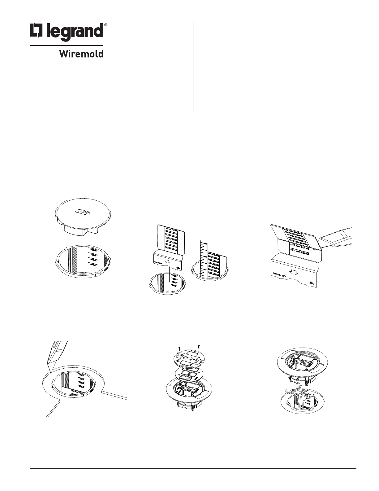
Ratchet-Pro Slide Cover
I N S T A L L A T I O N I N S T R U C T I O N S
nstallation Instruction No.: 1 003 720 R2 – Updated May 2009
I
Products Covered: 881AMD8TC, 897CTC, 897CFFTC, 881CTC, 881RC4TC, 881AV3CTC, 8814FFCTC
899CTC & 881CM2TC – For use in 4 1/2" [114.3mm] minimum concrete pours.
IMPORTANT: Please read all instructions
before beginning.
CAUTION: Do not operate tile stripper or resurfacing equipment over top of cover.
This may result in damage to the surface finish of the product.
For use in 4 1/2" [114mm] minimum concrete pours.
FLOOR BOX PREPARATION:
1. Remove protective concrete cap
from box.
881AMD8TC/881CTC/881AV3CTC COVER INSTALLATION
1. Cut a 6 1/2" [165mm] circular
concentric opening in the floor
covering.
2. For dual service applications, slide
partition onto the slots located on the
inside of the box and mark the partition
2" [51mm] below the top of the box.
Volume of power compartment is
reduced by the first legible calibration.
2. Remove the slide cover and gasket
to access the communications
compartments.
3. Remove the partition and break off
the top portion at the first calibration
below the mark made from step 2.
Reinstall the partition with the small
compartment being the
communications side.
3. Connect receptacle leads to circuit
conductors with twist-on wire
connectors or other approved
methods.
WARNING: Receptacle mounting means not grounded. Grounding
wire connection required. For isolated ground wiring,
connect ground leads to a separate isolated grounding
conductor (see NEC 250-146(d)).
Page 2
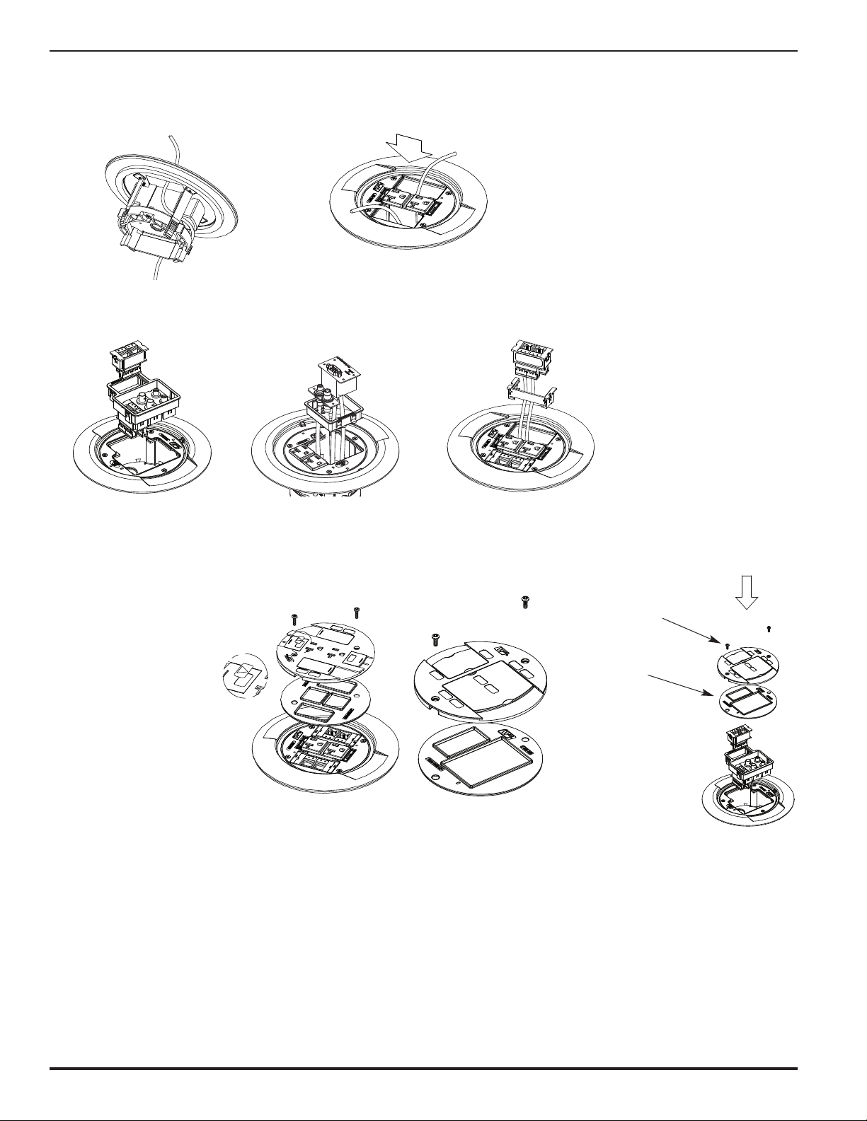
4. Pull the communications cables
through the cover. Route cable
around the receptacle shell for
devices opposite the communications
5. Orient the open side of the cover
adapter with the divided side of the
box and push into place – No glue
required!
compartment.
6. Wire and snap communication jacks into flange.
881AMD8TC Series
881AV3CTC Series
881CTC Series
7. Align gasket over receptacle and press bead into flange
channel. Reattach slide cover with two #6 screws.
NOTE: For Isolated ground
CAUTION: Gasket must be set
CAUTION: Receptacle supplied with this activation is not suitable for direct field wiring.
applications, apply
IG icon on receptacle
slide as shown.
in place to provide
scrub water seal.
Contact manufacturer for replacement. Field modifications will void UL Listing.
Replacement receptacle is limited to this manufacturer’s catalog No. RC37REC.
Slide Cover Mounting
Screws (2) #6-32
Align gasket over
communications opening
and press bead into
flange channel.
CAUTION: Gasket must be
set in place to
provide scrub
water seal.
2
Page 3
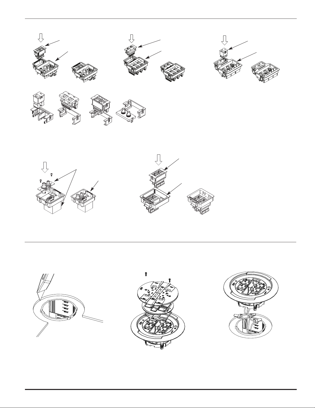
Pass & Seymour Activate Bezel &
CM Modules
Activate Cat 5e Jack
Activate Bezel
Ortronics Series II Bezel
Ortronics Series II Jack
Sold Separately)
(
rtronics Series II Bezel
O
Ortronics TracJack Bezel &
Communication Jack
rtronics TracJack
O
(Sold Separately)
Ortronics TracJack Bezel
Extron®Device Bezel –
Supplied with AV3CTC.
(Extron®Devices Sold Separately Through
Extron®Distributors Only)
®
xtron
E
(Not Supplied)
evice
D
Extron Device Bezel
(Supplied)
NOTE: This Bezel Accommodates (1) Single and (1)
Double or (3) Single MAAPs (Mini Architectural
Adapter Plates) Extron®Devices.
881RC4 COVER INSTALLATION:
1. Cut a 6 1/2" [165mm] circular
2. Remove the slide cover and gasket
concentric opening in the floor
covering.
Pass & Seymour ACTIVATE Bezel &
CM Modules – Supplied with AV3CTC
ctivate Cat 5e 2A Jack
A
(Sold Separately)
Activate Bezel
(Supplied)
to access the communications
compartments.
3. Connect receptacle leads to circuit
conductors with twist-on wire
connectors or other approved methods.
WARNING: Receptacle mounting means not grounded.
Grounding wire connection required. For
isolated ground wiring, connect ground
leads to a separate isolated grounding
conductor (see NEC 250-146(d)).
3
Page 4

4. Pull the communication cables
through the cover as shown.
5. Orient the cover so that the divider on
the underside of the cover lines up
with the divider inside the floor box.
6a. 881RC4 COMMUNICATION OPTIONS
Pass & Seymour Activate & CM2 Module Installation:
(
Modular Jacks sold separately)
Both Recessed
6. Wire and snap communication jacks
into flange.
Both Flush Recessed/Flush
Ortronics TracJack Installation
Four Cat 5e TracJack Modules (TracJack Modules sold separately)
Combination
Both Recessed Both Flush
Ortronics Series II Installation
(Series II Modular Inserts not included, sold separately.)
Both Recessed Both Flush Recessed/Flush
Recessed/Flush
4
Page 5

7. Align gasket over receptacle and press bead into flange
hannel. Reattach slide cover with two #6 screws.
c
CAUTION: Gasket must be set in place to provide scrub
NOTE: For Isolated ground applications, apply IG icon on
receptacle slide as shown.
water seal.
97CTC COVER INSTALLATION:
8
1. Cut a 6 1/2" [165mm] circular
concentric opening in the floor
covering.
4. Remove the slide cover, gasket, and
trim flange to access the
communications compartments.
CAUTION: Receptacle supplied with this activation is not
2. Connect receptacle leads to circuit
conductors with twist-on wire
connectors or other approved
suitable for direct field wiring. Contact manufacturer
for replacement. Field modifications will void UL
Listing. Replacement receptacle is limited to this
manufacturer's catalog No. RC4REC2.
3. Orient the open side of the adapter with
the divided side of the box and push
into place – No glue required!
methods.
WARNING:
Receptacle mounting
means not grounded.
Grounding wire
connection required.
For isolated ground
wiring, connect
ground leads to a
separate isolated
grounding conductor
(see NEC 250-146(d)).
5. Pull communication cables through
cover. Route cable around the
6. Wire and snap communication jacks
into flange.
receptacle shell for devices opposite
the communications compartment.
7. Align gasket over receptacle and
press bead into flange channel.
CAUTION: Gasket must be set in
place to provide scrub
water seal.
8. Re-attach cover with (2) #6 screws.
NOTE: For Isolated ground applications, apply
IG icon on receptacle slide as shown.
CAUTION: Receptacle supplied with this activation
is not suitable for direct field wiring.
Contact manufacturer for replacement.
Field modifications will void UL Listing.
Replacement receptacle is limited to
this manufacturer’s catalog No.
RC37REC.
5
Page 6

899CTC COVER INSTALLATION:
WHITE or NEUTRAL
from branch circuit
WHITE
from slide cover receptacle
BLACK or HOT
from branch circuit
BLACK
from slide cover receptacle
GREEN (jumper wire)
from cover adapter ring
GREEN
from slide cover receptacle
CONVENTIONAL WIRING SCHEMATIC
WHITE or NEUTRAL
from branch circuit
WHITE
from slide cover receptacle
BLACK or HOT
from branch circuit
BLACK
from slide cover receptacle
GREEN (jumper wire)
from cover adapter ring
ISOLATED GROUND
from branch circuit
GREEN
from slide cover receptacle
ISOLATED GROUND WIRING SCHEMATIC
GREEN or GROUND
from branch circuit
SYSTEM GROUND
GREEN or GROUND
from branch circuit
SYSTEM GROUND
1. Cut a 6 1/2" [165mm] circular
concentric opening in the floor
covering.
2. Remove the slide cover and gasket to
facilitate the routing of the
communication cables.
3. For communication cable pass-through,
remove the egress knockout(s) located
on the underside of the cover.
Pass-through
Knock Out
ut Slot in Gasket for
C
cable pass-through
4. Pull communication cables through box. Route one of the
cables around the receptacle for cable egress opposite the
communication compartment in the floor box. Reattach
slide cover with (2) #6 screws. Pass through cabling must
pass through internal gasket and slide cover.
lide Mounting Screw
S
(2) #6-32
Align Gasket over
Flange and press
bead into Flange
CAUTION: Gasket must be set in
place to provide scrub
water seal. Do not
over-tighten cover
mounting screws.
5. Connect receptacle leads to circuit conductors with
twist-on wire connector or other approved methods.
See schematic below.
CAUTION: Receptacle mounting means not
grounded. Grounding wire
connection required. For isolated
ground wiring, connect ground
leads to a separate isolated
grounding conductor (see NEC
250-146(d)).
6. If circuit is connected to an isolated ground, apply
IG Icon on receptacle slide as shown.
NOTE: The orange triangle shall only be placed on
devices that are wired for isolated ground.
See NEC 250-146(d).
7. Orient the open side of the cover adapter with the divided
side of the box and push into place – No glue required!
CAUTION: Receptacle supplied with this activation is not
suitable for direct field wiring. Contact manufacturer
for replacement. Field modifications will void UL
Listing. Replacement receptacle is limited to this
manufacturer’s catalog No. RC9REC.
6
Page 7

881CM2TC COVER INSTALLATION:
1. Cut a 6 1/2" [165mm] circular
oncentric opening in the floor
c
covering.
4. Attach conduit to conduit fitting, pull
wires and push activation into floor
box until firmly seated on floor.
2. Remove necessary screw plugs from
the flange.
1/4"
1
educing Ring
R
3. Attach a 2" or 1 1/4" trade size
conduit fitting (not supplied) to the
flange. If a 1 1/4" trade size fitting is
used, insert the 1 1/4" reducing ring
upplied before inserting the fitting.
s
897CFFTC/8814FFCTC COVER INSTALLATION:
1. Cut a 6 1/2" [165mm] circular
concentric opening in the floor
covering.
2. Remove necessary screw plugs from
flange. Removing the flange from the
adapter bracket may facilitate
easier wiring.
4. Push the activation into the floor box
until firmly seated against the floor.
CAUTION: Flange must be grounded.
Connect attached grounding
conductor to system ground.
Maximum circuit conductor size
shall not exceed No. 12 AWG.
3. Attach the necessary conduit fittings to
the flange. Connect the flexible conduit
and wires. All splices must be made in
the box below the cover adapter.
CAUTION: Flange must be
grounded. Connect
attached grounding
conductor to system
ground. Maximum
circuit conductor size
shall not exceed No.
12 AWG.
7
Page 8

olume Capacities for Ratchet-Pro PVC Floor Box
V
To calculate the total box
volume, use displacement
of the largest uncut
section remaining.
Single Service 895 &
896 Activations
Dual Service 895DCC
Activations
Dual Service 881TC,
881RC4ATC, 897CTC,
897CFFTC & 899CTC
Activations
Single Service
881CM2TC
Activations
Single Service
881AV3, 881AMD8,
8814FF & 897CFF
Activations
BOX HEIGHT WIRING VOLUME WIRING VOLUME WIRING VOLUME WIRING VOLUME WIRING VOLUME
(with Divider) (with Divider)
Inches [mm] Cu. Inches [mm] Cu. Inches [mm] Cu. Inches [mm] Cu. Inches [mm] Cu. Inches [mm]
6 [152.0] 65.0 [1065.0] 15.0 [738.0] 27.9 [457.0] 47.9 [784.0] 20.0 [327.0]
5 1/2 [140.0] 58.0 [950.0] 39.3 [644.0] 22.2 [364.0] 40.9 [670.0] 18.7 [306.0]
5 [127.0] 51.0 [835.0] 33.6 [551.0] 16.5 [270.0] 33.9 [554.0] 17.4 [284.0]
4 1/2 [114.0] 44.0 [720.0] 27.9 [457.0] 10.8 [177.0] 26.9 [440.0] 16.1 [263.0]
4 [102.0] 37.0 [605.0] 22.2 [364.0] 14.8 [241.0]
3 1/2 [89.0] 30.0 [490.0] 16.5 [270.0] 13.5 [220.0]
3 [76.0] 23.0 [377.0] 10.8 [177.0] 12.2 [200.0]
AUTION:
C
o not use in concrete
D
ours less than 4 1/2"
p
114mm]
[
CAUTION:
Do not use in concrete
pours less than 4 1/2"
[114mm]
© Copyright 2009 Legrand/Wiremold All Rights Reserved
WIREMOLD
U.S. and International:
60 Woodlawn Street • West Hartford, CT 06110
1-800-621-0049 • FAX 860-232-2062 • Outside U.S.: 860-233-6251
Canada:
570 Applewood Crescent • Vaughan, Ontario L4K 4B4
1-800-723-5175 • FAX 905-738-9721
1 003 720 R2 1209
 Loading...