

Page 1
Wiremold / Legrand electrical systems conform to and should be
installed and properly grounded in compliance with the
requirements of the current National Electrical Code, Canadian
Electrical Code or codes administered by local authorities.
All electrical products may represent possible shock or fire hazard
if improperly installed or used. Wiremold / Legrand electrical
products are UL Listed, and should be installed in conformance
with current local and/or the National Electrical Code.
Power Commander
®
POWER DISTRIBUTION UNITS
INSTALLATION INSTRUCTIONS
Installation Instruction No.: BK007R1 – Updated March 2007
The Wiremold Power Commander®Power Distribution Units are UL/ cUL Listed/ Recognized by Underwriters Laboratories, Inc
under File E173292. All products are in compliance with the national Electrical Code and the Canadian Electrical Code.
The 3A, 3B, and 4B Series are UL/ cUL Listed and comply with the Standard for Information technology Equipment – Safety – Part 1.
UL60950-1. They are available in a 1 5/8" W x 2 7/8" H [41mm W x 73mm H] housing with variable length.
The 3A and 3B models are rated 120Vac, 24A. Each circuit may carry up to 12A as long as the total current does not exceed 24A.
The 4B Series is rated 208Vac, 32A. Each circuit may carry up to 16A as long as the total current does not exceed 32A.
The JPDU-A is UL/cUL Recognized and complies with the Standard for Information Technology Equipment, UL1950.
The JPDU-A is rated 120Vac, 24A. Each circuit may carry up to 12A as long as the total current does not exceed 24A.
The D-Series Custom Power Distribution Units are UL/cUL Listed and comply with the Standard for Information Technology
Equipment – Safety – Part 1, UL60950-1. They are available in a 2" W x 1 3/4" H [51mm W x 44mm H] housing with variable length.
The D-Series is rated 120Vac, 12 A or 16A depending on the configuration ordered.
j
CAUTION: The socket outlet that
powers the PDUs should
be installed nearby and
be easily accessible.
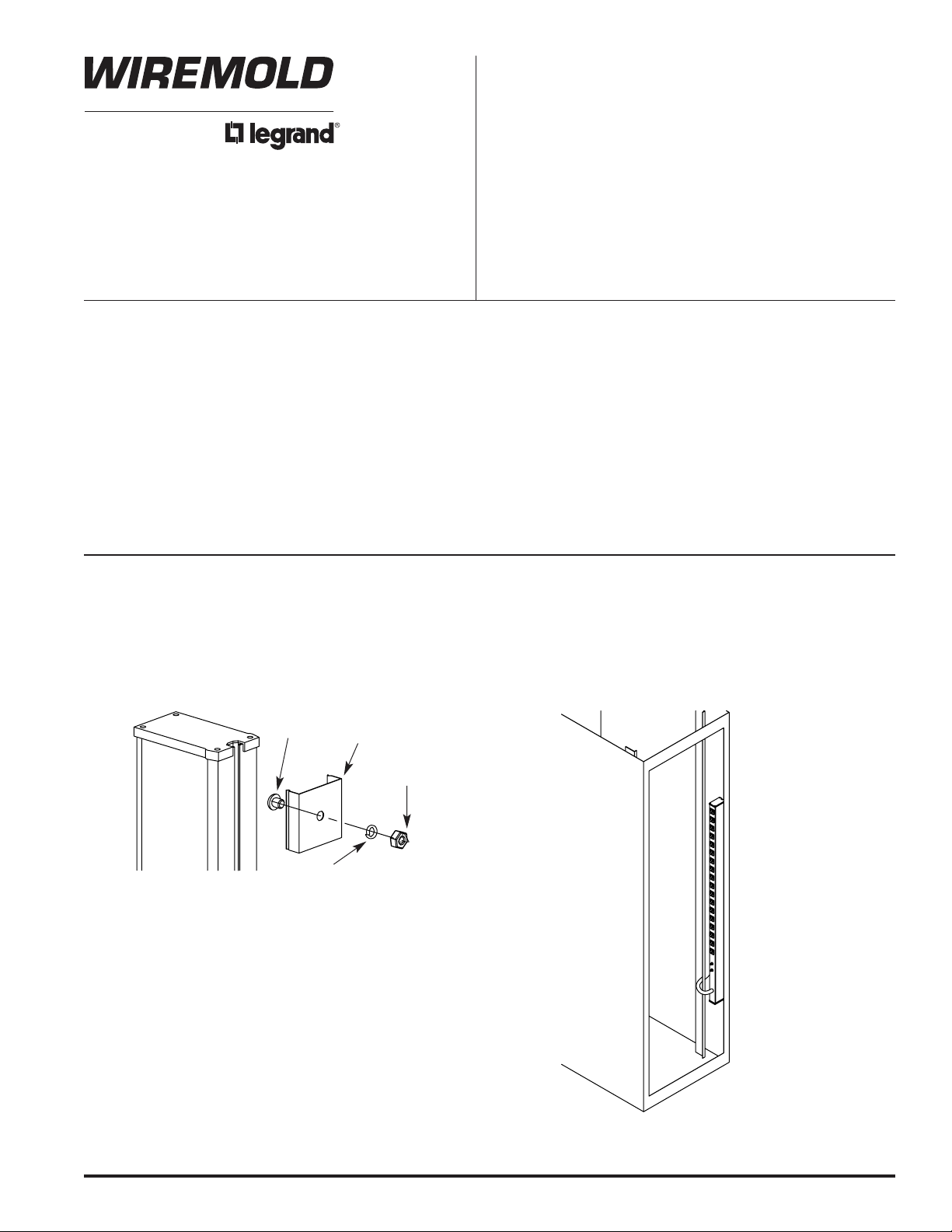
STANDARD HARDWARE INSTALLATION
Attach the Spring Clips to the cabinet frame or cabinet wall making sure the top clip is no more than 1
inch [25mm] from the top of the unit. Insert the 1/4 - 20 Phillips screw through the spring clip as shown,
and then through the cabinet frame or cabinet wall. On the other side of the mounting surface, put the
1/4 lock washer over the exposed Phillips screw and tighten into place with the 1/4 - 20 nut. Once the
spring clips are secure, place unit in one side of the clips and snap the other side into position.
1/4-20
Phillips
Spring
Clip
1/4 Lock
Washer
1/4-20
Nut
Page 2
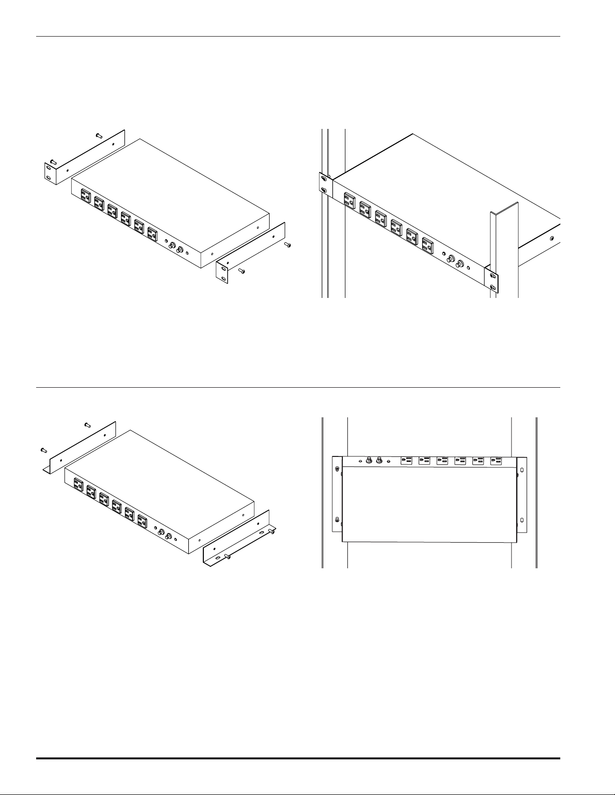
JPDU-A FRONT MOUNT (1U) INSTALLATION MOUNTING INSTRUCTIONS:
JPDU-A SIDE RAIL (0U) INSTALLATION MOUNTING INSTRUCTIONS:
With a 5/16" nut driver, unfasten the set of 10-32 Hex head
machine screws on each side of JPDU-A. Take one of the front
mounting brackets and align each side hole with the side hole
on JPDU-A. Attach one front mounting bracket using two of
the unfastened 10-32 Hex screws. Repeat installations steps
for the other front mounting bracket as shown above.
Install JPDU-A in a cabinet or 19" [483mm] rack using
appropriate hardware (not provided) for mounting.
With a 5/16" nut driver, unfasten the set of 10-32 Hex head
machine screws on each side of JPDU-A. Take one of the
rear mounting brackets and align each side hole with the
side hole on JPDU-A. Attach one rear mounting bracket
using two of the unfastened 10-32 Hex screws. Repeat
installations steps for the other rear mounting bracket as
shown above.
Install JPDU-A in a cabinet or 19" [483mm] rack using
appropriate hardware (not provided) for mounting.
The JPDU-A has two 12 amp circuits which are indicated by the two LEDs in the front of the unit.
Each circuit is protected by a 15 amp circuit breaker and 280V clamping level surge protection. A
lighted LED indicates that the circuit is functioning properly and is surge protected. A non-lighted
LED indicates that the circuit is not functioning properly and/or is not surge protected.
Page 3

RECOMMENDED MOUNTING INSTRUCTIONS - Remote Display:
All “-RAM” models contain a remote display unit which can be mounted in a 1U rack mount face plate. To install remote display,
remove black insert and push pins from the rack mount face plate to clear the desired display location. Use a flat screw driver to
gently pry up the push pin head followed by the push pin body so they are not separated.
Line up the remote display unit with the cleared holes in the rack mount face plate and insert the push pins through the pin holes
as indicated. Once secured, install the face plate into your 19" [482mm] rack via the closed slots.
Remote Display
Push Pins
Insert
Rack Mount
Face Plate
(Closed Slots
for Rigidity)
Designed in Accordance
with E. I. A. Standards
MOUNTING TYPES - Snap-On/ Slide-Off:
Mount unit in any position. Catalog No. 8004 includes two aluminum mounting
clips that snap onto mounting rails on the back of the unit. Screws also included.
Used for all units with 2" [51mm] aluminum housing.
Page 4

Wiremold / Legrand
U.S. and International:
60 Woodlawn Street • West Hartford, CT 06110
1-800-621-0049 • FAX 860-232-2062 • Outside U.S. 860-233-6251
Canada:
570 Applewood Crescent • Vaughan, Ontario L4K 4B4
1-800-723-5175 • FAX 905-738-9721
BK007R1 – Updated March 2007 – For latest specs visit www.wiremold.com
© Copyright 2007 Wiremold / Legrand All Rights Reserved
CAUTION: The three-prong, grounding type plugs in all units are for use with 3-prong, grounded receptacles only. Modifying
or bypassing the ground pin for use in a non-grounded receptacle may lead to electrical shock, is not recommended and
voids the product warranty. All units are designed for interior use in dry locations only. Check all local and national electrical
codes for proper installation.
ABOUT YOUR WIREMOLD PRODUCT: Each unit is 100% tested prior to packaging. Power Commander
®
products are
specifically made for use in the IT environment. These units are rated for 30 amps, 120 volts, 60 Hz or 40 amps, 208 volts,
60Hz. Consult product label for details.
TROUBLESHOOTING: If you are receiving no power to your Wiremold product, first make sure the unit is plugged firmly into
your wall outlet. Plug the unit into a different wall outlet to verify the condition. If there is still no power, the built-in circuit
breaker may need to be reset. If you are still having problems, please call technical support.
Understanding that each cabinet, enclosure, rack and application is unique, Wiremold has designed
four solutions for mounting the 30 Amp Power Distribution Units using the universal T-slot built into the
unit. The mounting kits listed below are available for purchase as accessories.
Catalog No. 30A-MK1 – Z Bracket
Sturdy anodized aluminum bracket
offsets the unit for front access to the
mounting. May be used for a side or
end mount.
Catalog No. 30A-MK2 – L Bracket
Allows mounting at a right angle. May
be used for a side or end mount.
Catalog No. 30A-MK3 – Swivel Bracket
Allows unit to be mounted then rotated up
to 270° (dependent on mounting location)
providing easy access to unit’s face
without losing space.
Catalog No. 30A-MK4 – Drop-In Clip
Clip is mounted directly on the unit and
allows the strip to install with a “drop
and hold” method that requires no
additional hardware.
NOTE: Accessory mounting kits are not UL Listed.
MOUNTING ACCESSORIES
 Loading...