

Page 1

USER MANUAL
• IP Video Server 1ch - IP Video Server 1ch
4 306 24 / 25
LE04770AA
ACT Net ALM Video
RS232
MIC
SPK
IR
Reset
Page 2

2
Indice
1 Accessories ........................................................................................................................... 4
2 General Introduction ................................................................................................................... 5
2.1 Overview ........................................................................................................................... 5
2.2 Features ........................................................................................................................... 5
2.3 Specications ......................................................................................................................... 6
3 Framework ...........................................................................................................................12
3.1 Front panel ........................................................................................................................... 12
3.2 Rear panel 1ch NVS ................................................................................................................ 13
3.3 Rear panel 4ch NVS ................................................................................................................ 14
4 Quick Conguration Tool ............................................................................................................ 15
4.1 First Connection ..................................................................................................................... 15
5 Connecting to a Device and Opening the Web Application ..................................................... 23
5.1 PC Conguration .................................................................................................................... 23
5.2 Connection with the Search Tool .......................................................................................... 24
5.3 Connection with Internet Explorer ....................................................................................... 25
5.4 Login ........................................................................................................................... 25
6 Main Interface Introduction ....................................................................................................... 27
6.1 Log in ........................................................................................................................... 27
6.2 Monitor Channel Menu Tree ................................................................................................ 28
6.3 System Menu .......................................................................................................................... 29
6.4 Monitor Window Switch ........................................................................................................ 30
6.5 Preview Window Switch ........................................................................................................ 30
6.6 PTZ Control ........................................................................................................................... 30
6.7 Color and More Setup ............................................................................................................ 31
7 Congure ........................................................................................................................... 32
7.1 System Information ............................................................................................................... 32
7.2 System Conguration ........................................................................................................... 34
7.3 Advanced ........................................................................................................................... 50
7.4 Additional Function ............................................................................................................... 56
Page 3

3
8 Search ........................................................................................................................... 59
9 Alarm ........................................................................................................................... 61
10 About ........................................................................................................................... 62
11 Log out ........................................................................................................................... 63
Annex 1: No-IP DDNS ........................................................................................................................ 64
Annex 2: Using Google Chrome ....................................................................................................... 70
Annex 3: Using Firefox ..................................................................................................................... 72
Annex 4: Using IE8 ........................................................................................................................... 74
Annex 5: Email Function ................................................................................................................... 77
Annex 6: Routers conguration ....................................................................................................... 80
Page 4

4
1 Accessories
Name Qty
Network video server 1
12V power adapter 1
Multiple function connector cable
data to DB9 male com cable
1
Quick Start Guide 1
CD 1
Page 5

5
2 General Introduction
2.1 Overview
This device adopts audio video data collection, transmission and storage. It can connect to the network directly without
any auxiliary device.
This device uses standard H.264 video compression technology which maximally guarantees the video quality.
It can be used alone or used in a network area. When it is used lonely, it can be connected to the network and used from
a network client-end.
2.2 Features
User Management
Dierent user rights for each group, one user belongs to one group.
The user right shall not exceed the group right.
Data Transmission Support cable network data transmission via Ethernet.
Storage Function
Support central server backup function in accordance with conguration and setup
in alarm or schedule setting.
Support record via Web and the recorded le are stored in the client-end PC.
Support local SD card hot swap.
Alarm Function
Real-time respond to local alarm input and video detection as user pre-dened
activation setup and exert audio prompt(allow user to pre-record audio le).
Realize real-time video detect such as motion detect, camera masking and video
loss.
Network Monitor
Supports one-channel audio/video data transmit to network terminal
Max supports 10 connections.
Adopt the following audio and video transmission protocol: HTTP, TCP, UDP, MULTICAST, RTP/RTCP and etc.
Support web access, widely used in WAN.
Network Management
Conguration and management via Ethernet.
Support device management via web.
Support various network protocols.
Peripheral Equipment
Support peripheral equipment connection via the RS232 port.
Support serial port (RS232/RS485) transparent data transmission.
Power External power adapter. Support DC 12V.
Page 6

6
2.3 Specications
2.3.1 Function specication
Model
Parameter
Ref. 4 306 24 Ref. 4 306 25
Audio video
Video input
1-ch analog video input. BNC port.
Level: 1.0Vp-p. Resistance: 75Ω
4-ch analog video input. BNC port.
Level: 1.0Vp-p. Resistance: 75Ω
Video output
1-channel analog video output. BNC port. Level: 1.0Vp-p. Resistance: 75Ω
Support composite video output (with OSD output).
Resolution D1/CIF/QCIF/QVGA
Audio input
1-ch audio input. BNC port. Level:
1.0Vp-p. Resistance: 75Ω
4-ch audio input. BNC port. Level:
1.0Vp-p. Resistance: 75Ω
Audio output 1-channel bidirectional talk output 3.5mm JACK LINE OUT.
Performances
Standard PAL: 1f/s ~ 25f/s
Encode Capability H.264 encode
Encode Bit Stream
D1 (704 * 576)
HD1 (352 * 576)
CIF (352 * 288)
QCIF (176 * 144)
Video Recording Speed
D1: 1f/s-25f/s for each channel
(Adjustable)
D1: 1f/s-25f/s for each channel
(Adjustable).
CIF: 1f/s-25f/s for each channel
(Adjustable)
Network Capacity Max support 10 network users to monitor simultaneously
Power Consumption < 5W
Power DC 12V
Temperature - 10°C ~ + 50°C
Working Environment Humidity 10% ~ 90%
Dimension (H * W * D) 137 mm * 162 mm * 30 mm
Specications Note
Video
Resolution D1/HD1/CIF/QCIF/QVGA
Video compression Standard H.264 encode/decode format
Motion Detection
Take 18 * 22 pix as a macro unit
Support 396 detection zones
Sensitivity level ranges from 1 to 6
Dual-stream 1-channal real-time D1 + 1-channel CIF
Audio
Bidirectional Talk Bidirectional talk. Delay within 200ms
Audio Listening Audio listening. 1-ch MIC input
Network
WEB access via IE browser
PPPoE dial function
DHCP auto get IP address
DDNS
SMTP email function
NTP time synchronization
DNS domain parse
IP address lter
Page 7

7
Specications Note
Record
Schedule Record
Support max 6 periods
(This series product does not support this function.)
Manual Record
After enabling manual record, no matter system is in
schedule or alarm status or not, system just begins
recording
Alarm Record
System automatically enables recording function
when alarm occurred
Motion Detection Record
When video changes, system automatically enables
record operation
OSD
Time Title Display
There are 255 layers
- is the bottom layer and 255 is the highest layer
- means completely transparent and 255 is opaque
Channel Title Display Please refer to the above information
Privacy Mask Max supports 8 zones
Storage
Local Micro SD storage Support high-speed card/low-speed card
Based on SDK network storage Supported
Alarm
Network alarm/local alarm
output
2-ch local/network alarm output
Local alarm/network alarm input 4-ch local/network alarm input
Event Management
Activate alarm via motion
detection or external input
Please enable pre-record function when activating
the alarm
Upload image email. Upload automatically
Send out alarm notice via email,
HTTP and external port.
Support de-jitter when alarm occurs frequently
Support video short time buer
storage before or after alarm
Pre-record is 2Mbytes. Buer storage video of 5s
Control RS485 PTZ control Support various protocols
On-line Upgrade Network remote upgrade Use upgrade tool
Device Management Network client-end Log in the client-end software in the PC to monitor IPC
Parameter Conguration
NVS provides device information, video information, COM setup, record setup, motion
detection setup, alarm setup, OSD information interfaces to modify system setup
NVS provides running information such as user port, log, status, user management,
email setup, date modication
Log
System can record the important event log record
Record the following information:
System operation, setup operation, alarm event, record management, user
management, clear log
Water Mark To avoid vicious video modication
Power supply DC12V power supply
RESET Support hardware reset. System needs to reboot to activate the default setup
Page 8

8
2.3.3 Factory Default Setup
Please refer to the following sheet for factory default setup information.
Function conguration type Item Name Default setup
General Setup
Date format Y-M-D
DST Disable by default
Date separator ‘ _ ’
Time format 24H
Language English
When HDD is full Overwrite
Record duration 60 min
Device No. 8
Video type PAL
Encode Setup
Main stream
Channel Channel 01
Compression
H.264
Enable audio and video
General bit stream Main stream
Resolution D1
Frame rate 25
Bit stream control CBR
Bit stream value 2048
I frame interval control 50
Extra stream
Extension stream Main stream
Audio/Video enable Enable video
Resolution CIF
Frame rate 25
Bit stream control VBR
Quality High
Bit stream value 512
I frame interval control 50
Image color
Brightness: 50
Contrast: 50
Saturation: 50
Hue: 50
Watermark
Enable
Stream type: all
Type: Character
Character: Digital CCTV
Privacy Mask Never
Time title Enable. OSD transparent: 128
Channel title Enable. OSD transparent: 128
Schedule setup
Channel Channel 01
Pre-record 5 seconds
Time Setup
Start time 0:00:00
End-time 23:59:59
Record Period 1 : Enable motion detection/alarm
Page 9

9
Function conguration type Item Name Default setup
Schedule setup Time Setup
Snapshot Period 1 : Enable motion detection/alarm
Week Sunday
RS232 Setup
Option COM01
Function Console
Data bit 8
Stop bit 1
Baud rate 115200
Parity None
Network setup
Ethernet Port 01
DHCP Disable
IP address 192.168.1.108
Subnet mask 255.255.0.0
Gateway 192.168.0.1
Device name Device factory default name
TCP port 37777
HTTP port 80
UDP port 37778
Max connection 10
Network transmission QoS Disable
Remote host Multiple broadcast group
IP address 239.255.42.42
Port 36666
Email setup Disable
Multiple DDNs Disable
NAS setup Disable
NTP setup Disable
IP Filter Disable
Alarm setup
Event type Local input
Alarm input Input 01, disable
Type Normal open
Setup
Period: Start time 0:00:00
End time: 23:59:59
Period 1:enable
Week: Sunday
Anti-dither 0 second
General output Disable
Alarm latch 10 seconds
Record channel 1, enable
Record latch 10 seconds
Send email Enable
PTZ activation
Disable
Event type: never
Address: 0
Snapshot Disable
Page 10

10
Function conguration type Item Name Default setup
Video detection
Event type Motion detection
Channel Ch01, Disable
Sensitivity 3
Time period setup
Period:
Start time 0:00:00
End time:23:59:59
Period 1:enable
Week: Sunday
Anti-dither 5 seconds
Alarm output Disable
Alarm latch 10 seconds
Record channel Disable
Record latch 10 seconds
Send email Disable
PTZ activation
Event type: Never
Address: 0
Disable
Snapshot Disable
PTZ Setup
Channel Channel 01
Protocol DH-SD1
Address 1
Baud rate 9600
Data bit 8
Stop bit 1
Parity None
Default and Backup
All Disable
General Disable
Encode Disable
Schedule Disable
RS232 Disable
Network Disable
Alarm Disable
Video detection Disable
Camera Disable
Maintain Disable
Channel No. Disable
Advanced
Abnormity
Even Type No disk, Disable
Alarm
Output
Disable
Alarm Latch 10 seconds
Send email Disable
User account
admin/admin (reusable)
888888/888888(reusable)
666666/666666(reusable)
default
Snapshot Channel Channel 01
Page 11

11
Function conguration type Item Name Default setup
Advanced
Snapshot
Snapshot
mode
Snapshot_Timing
Frame rate 1f/s
Resolution D1
Quality 60%
Auto maintain
Auto reboot 2.00 each day
Auto delete
old les
Never
SN 1
IP 0.0.0.0
Port 7000
DNS Setup
DNS 221.123.33.228
Alternative DNS 221.12.1.228
Page 12

12
3 Framework
3.1 Front panel
Refer to the following sheet for detailed information.
Indication light /Port Function / Port Color Note
ACT
Power/working status
indication light
Red / Green
When connected to power: Red
When device is working normally: Green
light is on.
When device is upgrading: Green light is
ashing.
NET
Wireless network
status indication light
Green
Wireless connection ok: light is on
Wireless network is abnormal: light is o
ALM
Alarm status
indication light
Red
Device is armed: Light is on.
There is data transmission: Light is ashing.
Device is disarmed: Light is o.
Video
Transmission/record
status indication light
Blue
Video transmission is normal: Light is on.
Video transmission is abnormal: Light is o.
RS232 232 debug COM
For common COM debug, congure IP address
to transmit transparent COM data.
MIC MIC Audio input port.
SPK SPK Audio output port.
IR
IR remote control
port.
To receive the IR control signal from the
remote controller.
Reset RESET button
Device reset button.
Press it for 5 s to restore factory default setup.
Page 13

13
3.2 Rear Panel 1ch NVS
Refer to the following sheet for detailed information.
Port name Connection Function
V-IN Video input port BNC
Receive the signal from the front-end device such
as camera or speed dome
V-OUT Video output port BNC
Output analog video signal.
It can connect to the TV monitor to view video
A-IN Audio input port Input analog audio signal
SD SD card port Input SD card
1/2/3/4
1-4 channel alarm
input port
Alarm input port to receive the relay signal from
the external alarm device
G
Alarm input port
ground end
Alarm commun port
NO/C-1
NO/C-2
2-ch alarm output
Alarm output port: Output alarm signal to the
alarm device
NO/C-1: NO alarm output 1
NO/C-2: NO alarm output 2
A, B RS485 Port
RS485 port to connect to the control devices such
as speed dome PTZ
Wireless port
Connect to the wireless antenna to receive
WIFI,3G and et signal
NET Network port
10M/100M self-adaptive Ethernet port Connect to
the network cable
12VDC Power port Input 12V DC
Page 14
14
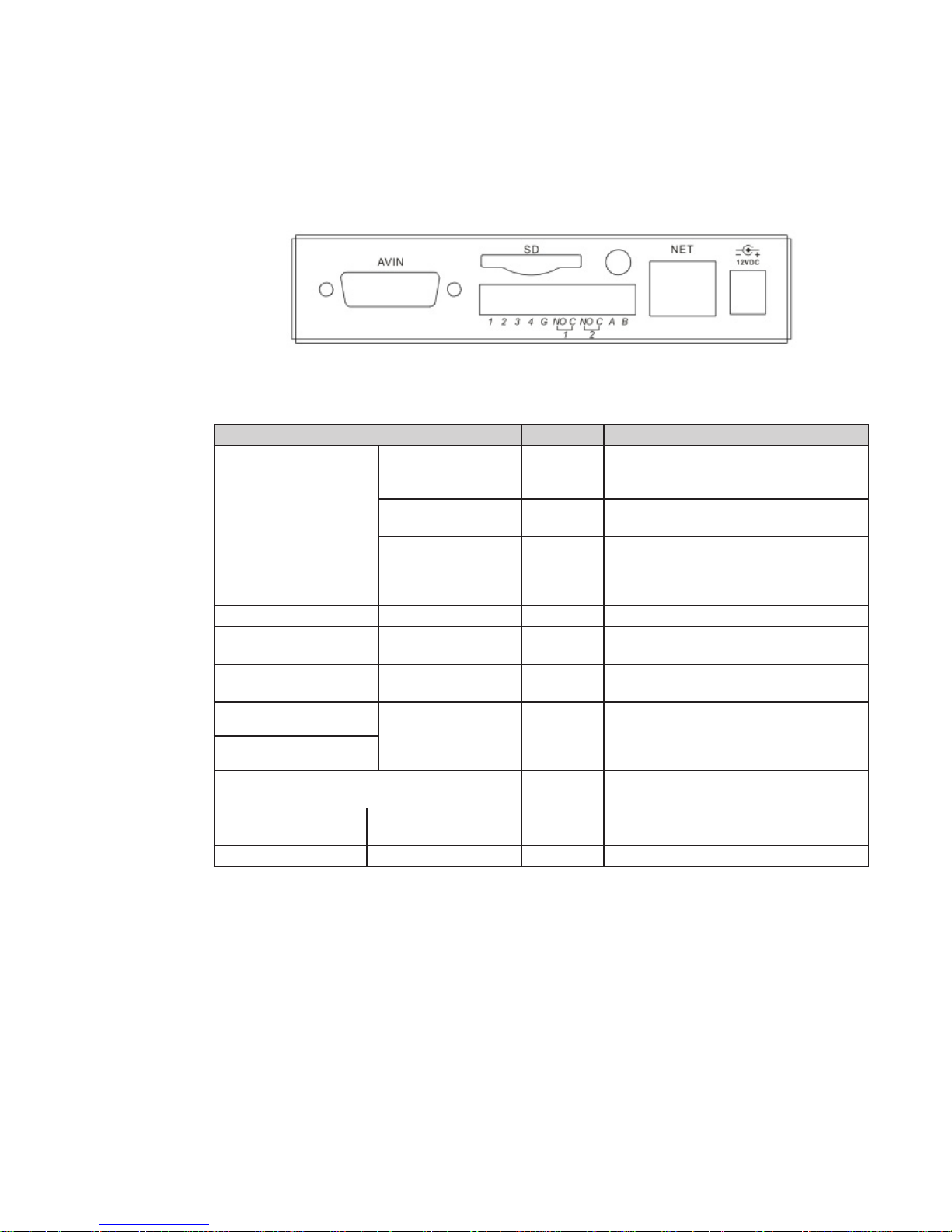
3.3 Rear Panel 4ch NVS
Refer to the following sheet for detailed information.
Port name Connection Function
AVIN
Video input port BNC
4 video input ports to receive the signal from
the front-end device such as camera or speed
dome.
Audio input port BNC
4 audio input ports to receive the analog
audio signal from the pickup or mike.
Video output port BNC
1 video output port to output analog video
signal.
It can connect to the TV monitor to view
video.
SD SD card port Input SD card
1/2/34
1-4 channel alarm
input port
Alarm input port to receive the relay signal
from the external alarm device
G
Alarm input ground
end
Alarm commun port
NO/C-1
2-ch alarm output
Alarm output port: Output alarm signal to the
alarm device.
NO/C-1: NO alarm output 1
NO/C-2: NO alarm output 2
NO/C-2
A B
RS485 port to connect to the control device
such as speed dome PTZ.
NET Network port
10M/100M self-adaptive Ethernet port.
Connect to the network cable.
12VDC Power port Input 12V DC power.
Page 15
15
4 Quick Conguration Tool
The quick conguration tool allows you to search for a device's IP address, even if it is in another segment (cameras, DVR,
NVR, encoders and decoders) and to modify it. The conguration tool is available on the CD supplied with the product.
It also allows the software to be upgraded or certain parameters to be modied.
This tool is used to connect to devices with an IP address in the same segment only.
4.1. First Connection
4.1.1 Connection with the conguration tool (to change the IP address or upgrade a device's internal software)
To open the software, double click the "CongTool.exe" icon on the CD supplied with the product.
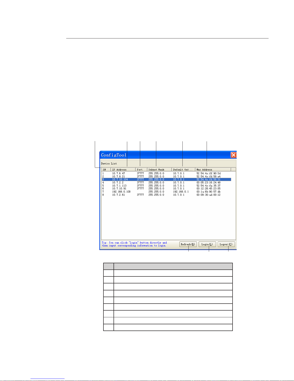
To search for devices connected to the network:
- Click the "Refresh" button; the tool will search for devices connected to the network and display it in the form of a list.
Description
1
Number
2
Device IP address
3
Device TCP port
4
Device subnet mask
5
Device default gateway
6
Device MAC address
7
Refresh the list
8
Access to the camera's network conguration menu
9
Disconnection from the camera's network conguration menu
1
2
3
4 5
6
7
8
9
Page 16
16
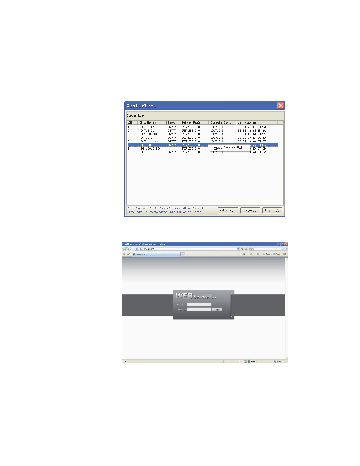
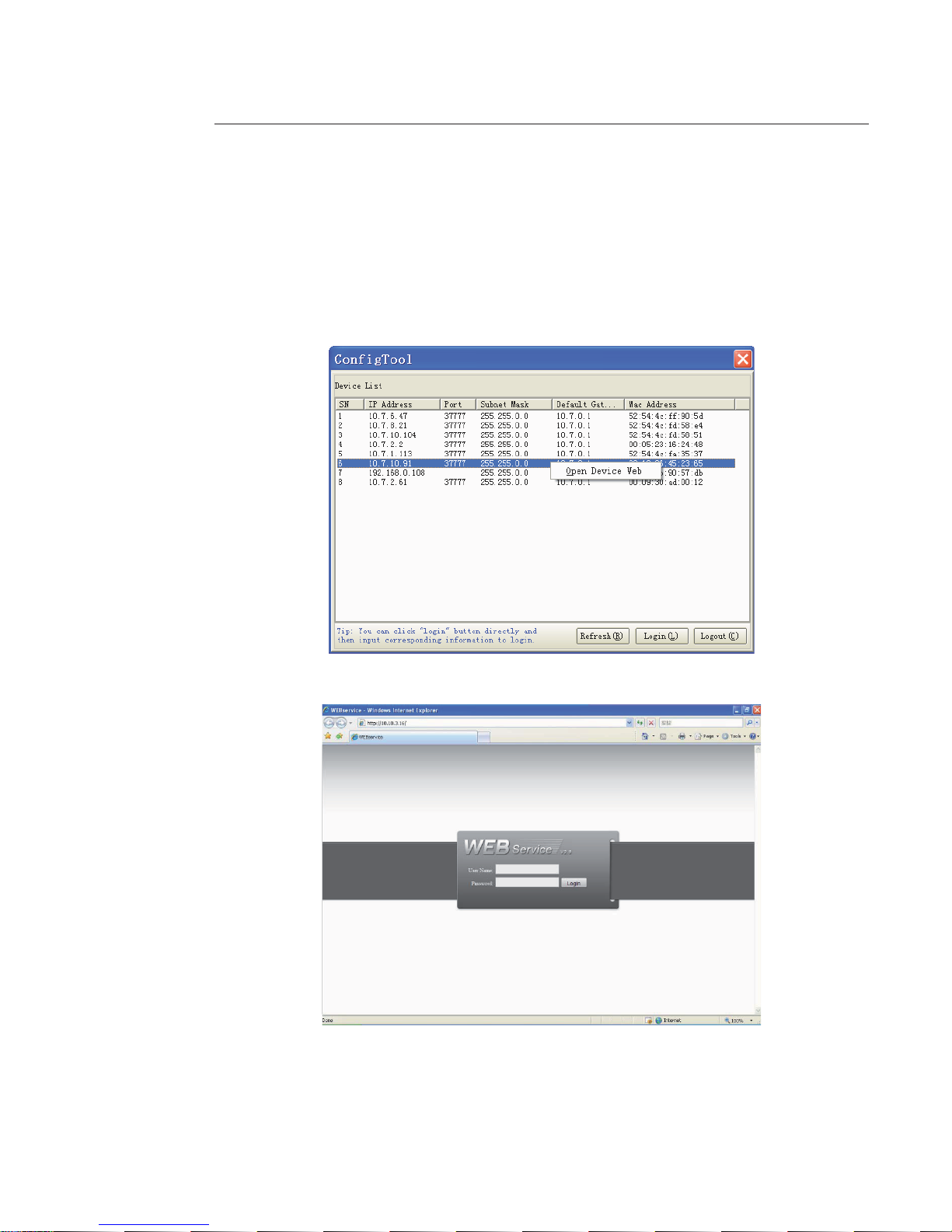
To connect to a device and open the web application:
- Highlight it (single click in the list).
- Right click the highlighted line.
- Click on "Open Device Web".
- The following web page opens:
If the connection fails:
- either the camera does not have an IP address in the same segment as the PC (see chapter 4.1.2 to change it),
- or the Internet Explorer security parameters are not set correctly (see chapter 5 to change them).
Page 17
17
4.1.2 Connection with the conguration tool (to change the IP address or upgrade a device’s internal software)
To search for devices connected to the network:
- Click the «Refresh» button; the tool will search for devices connected to the network and display them in the form of a
list (see chapter 4.1.1 for details of the interface).
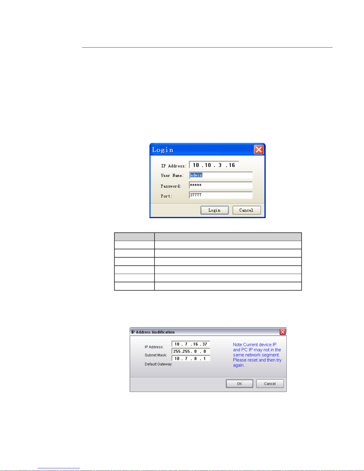
To connect to a device:
- Highlight it (single click in the list).
- Click on button 8 (or double click on the highlighted line).
- The following window opens:
Function Note
IP address Device IP address
User name Device user name
Password Device password
Port Device TCP port
Login Connection
Cancel Cancel
Click "Login" once the information has been entered.
If the following screen appears, this means that the device address is not in the same IP addresses segment as the PC on
which the conguration tool is currently running. It will therefore not be possible to connect.
- Manually modify the IP address by entering the desired new address.
- Click OK to save the new address in the device.
Page 18
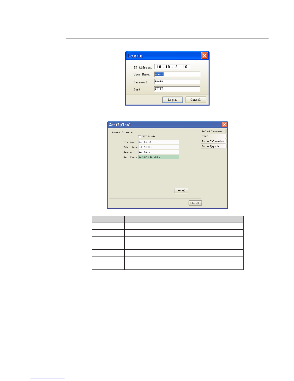
18
- Restart the procedure. The following window should open:
- Click Login to access the parameter modications.
Function Note
Enable DHCP Enable or disable the DHCP function
IP address Device IP address
Subnet mask Device subnet mask
Gateway Device default gateway
MAC address Device MAC address
Save Save
Return Return to the search interface
Page 19
19
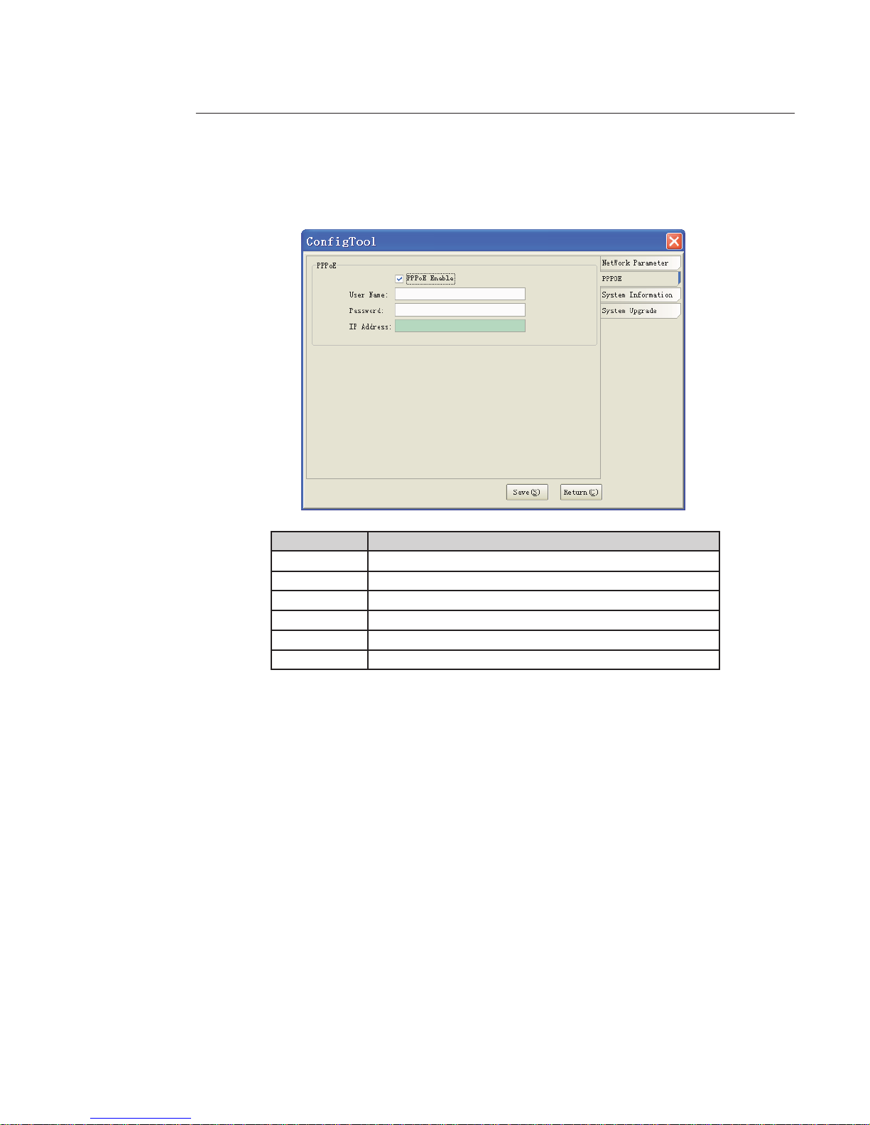
4.1.3 PPPoE
Select "PPPoE" on the right-hand side of the interface:
Function Note
Enable PPPOE Enable or disable the PPPoE function
User name PPPOE user name
Password PPPOE password
IP address Device IP address in the WAN
Save Save
Return Return to the search interface
- Click the "System Information" tab on the right.
Page 20
20
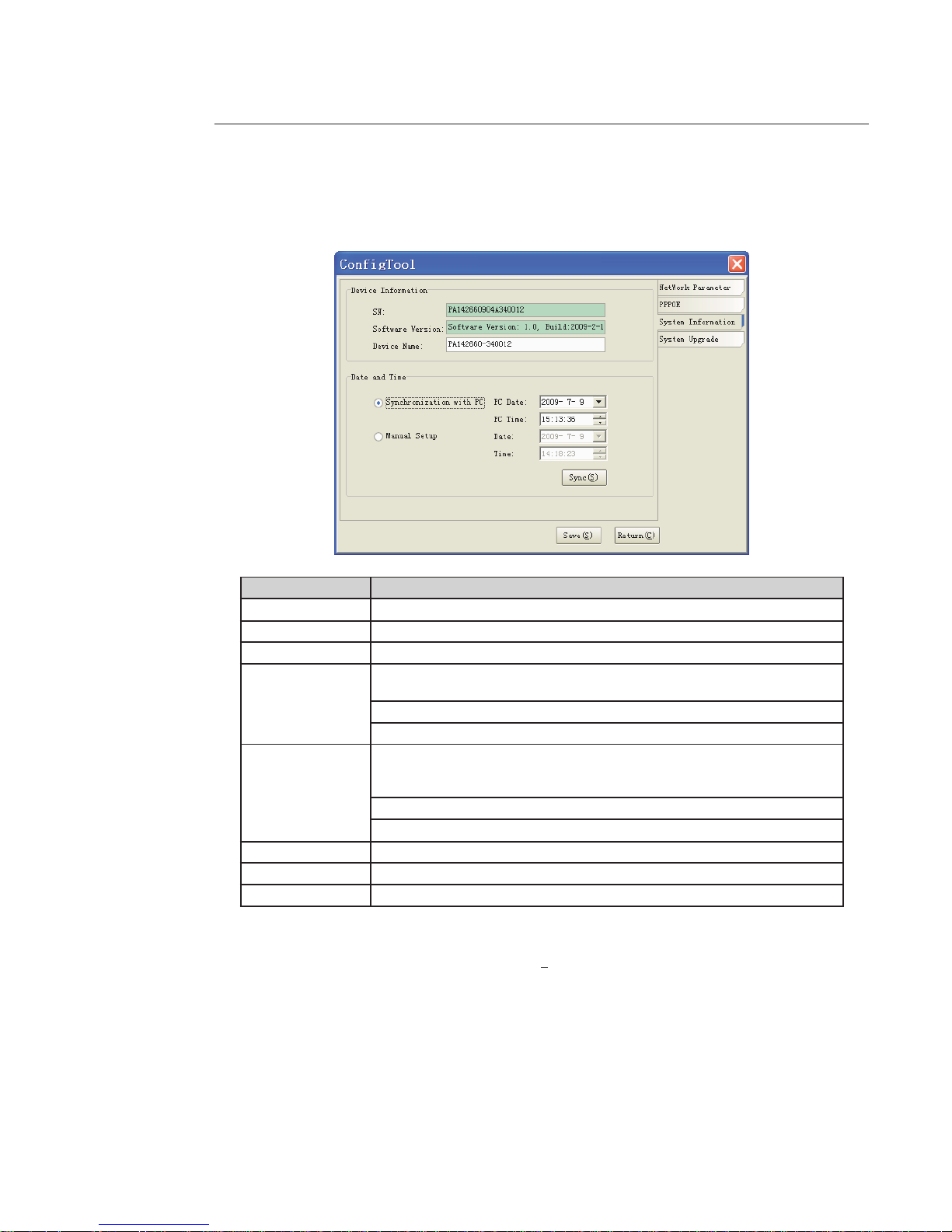
4.1.4 System
Select "System Information" on the right-hand side of the interface.
Function Note
SN Device serial number
Software version Device software version
Device name Model name
Synchronization
with PC
Synchronisation of the device date and time with the date and time on the PC.
Click "Sync" to synchronise, then "Save" to save the date and time.
PC date PC date
PC time PC time
Manual Setup
Manual setup of the device date and time.
Enter the desired date and time.
Click "Sync" to synchronise, then "Save" to save the date and time.
Date Date
Time Time
Sync Synchronise
Save Save
Return Return to the search interface
- By way of example, enter a camera name in the "Device Name" eld.
- Check that “Synchronization with PC” is selected, so that the date and time are synchronised with the PC.
- Check that the date and time are correct. If not, click “Sync(S) ”.
Page 21
21
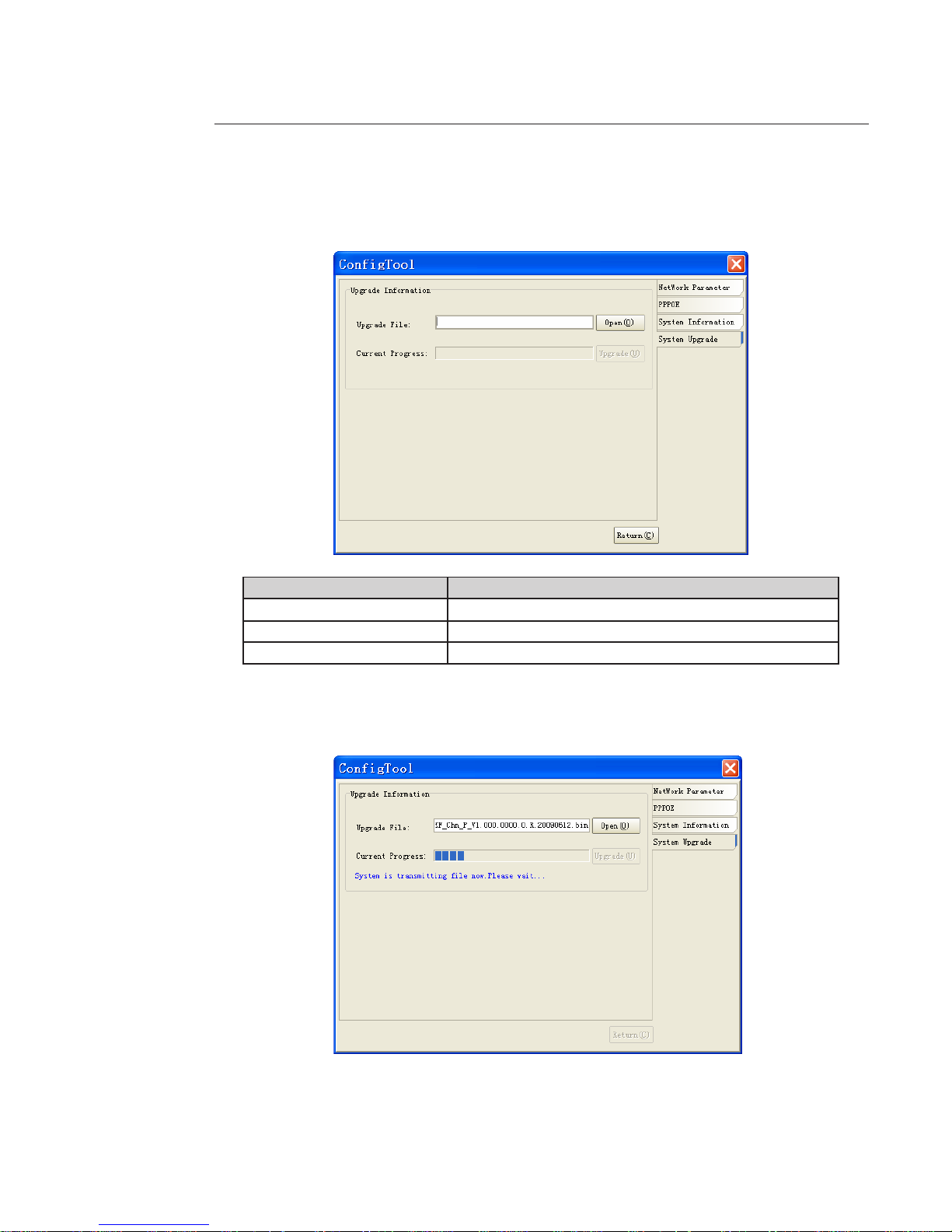
4.1.5 System Upgrade
Select "System Upgrade" on the right-hand side of the interface.
Function Note
Upgrade le/Open Click here to select the upgrade le.
Current progress/Upgrade Click here to start the upgrade procedure.
Return Return to search interface
Steps for updating the device's internal software
- Click on the "Open" button and select the *.bin internal software le.
- When the le has been added, click the "Upgrade" button; the le is then transmitted to the device.
Page 22
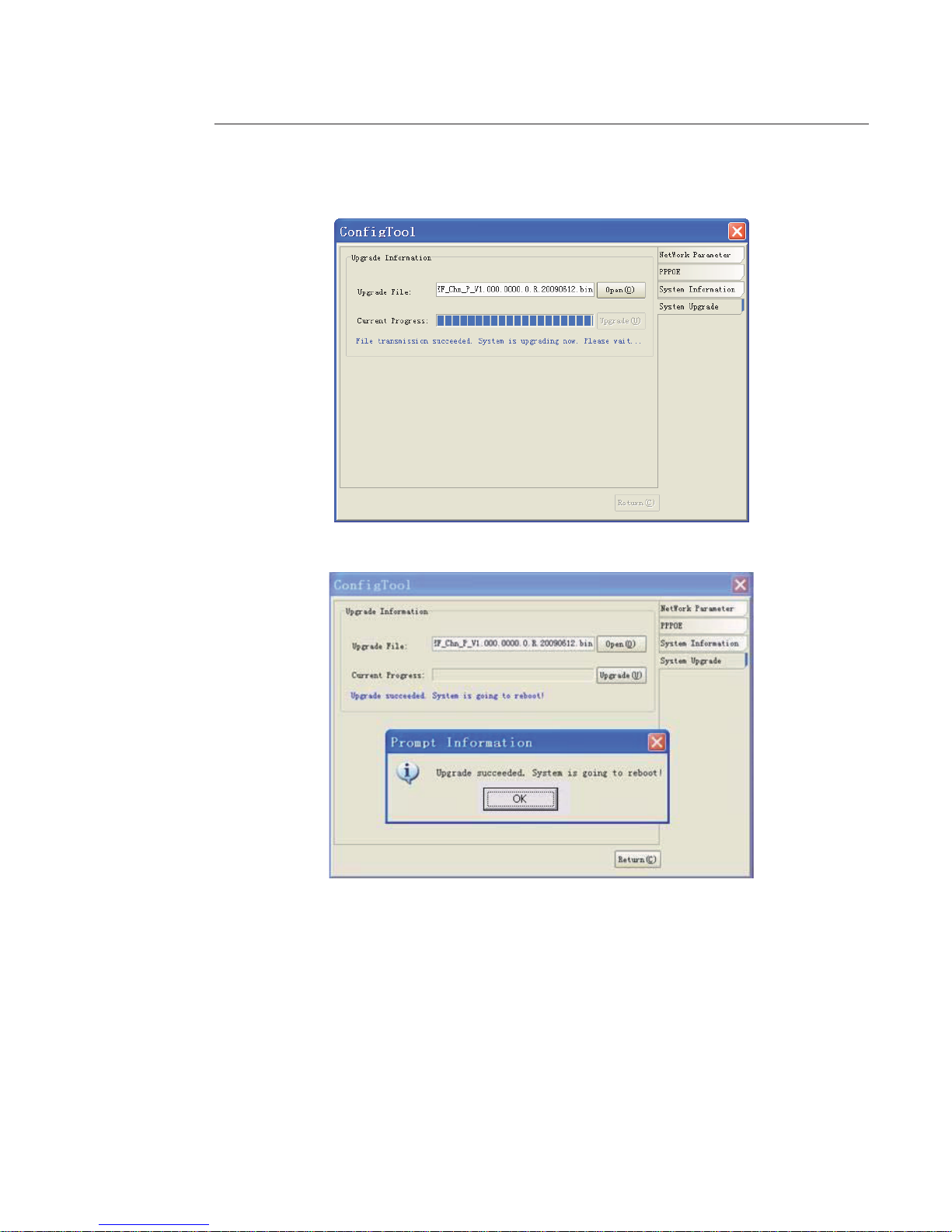
22
- Once the le has been transferred, the device upgrades automatically.
- Once the device has been upgraded, the following dialogue box opens:
- Click OK to nish the procedure.
Page 23
23
5 Connecting to a Device and Opening the Web Application
5.1 PC Conguration
This device supports Web access and management via PC.
Web includes several modules including monitor channel list, record search, alarm setup, system conguration,
PTZ control, monitor window, etc.
The system pops up warning information to ask whether you wish to install the control webrec.cab or not.
Click OK; the system can automatically install the control.
When the system is upgrading, it can overwrite the previous Web application too.
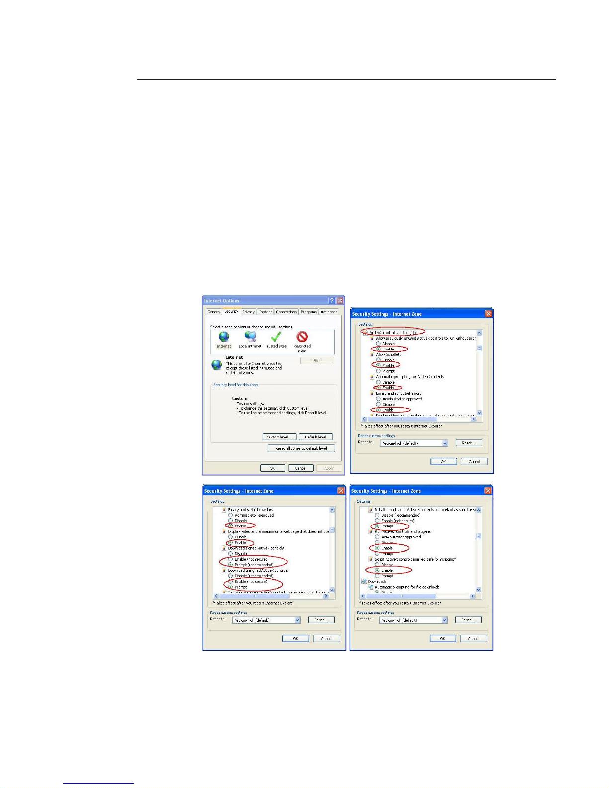
If you cannot download the ActiveX le, check whether you have installed the plug-in to disable the control download.
Alternatively you can lower the IE security level.
Page 24
24
5.2 Connection with the Search Tool
To open the software, double click the "CongTool.exe" icon on the CD supplied with the product.
To search for devices connected to the network:
- Click the "Refresh" button; the tool will search for devices connected to the network and display them in the form of
a list.
- Highlight the device required (single click in the list).
- Right click the highlighted line.
- Click on "Open Device Web".
- The following web page opens:
Page 25

25
5.3 Connection with Internet Explorer
IP camera factory default setup:
- IP address: 192.168.1.108.
- User name: admin
- Password: admin
Open Internet Explorer (IE) and enter your camera IP address in the address bar.
For example, if your camera IP is 192.168.1.108, then enter http://192.168.1.108 in the IE address bar.
Note:
If the connection fails:
- either the camera does not have an IP address in the same segment as the PC (see chapter 4.1.1 to change it),
- or the Internet Explorer security parameters are not set correctly
(see chapter 5.1 to change them).
5.4 Login
- Enter your user name and password.
(Default factory name is admin and password is admin.)
The login type includes: TCP/UDP/Multicast (depending on the device).
Input your IP
address here
Page 26

2626
After you log in, the main window appears:
Note: Use IE compatibility mode if you are using IE8 or above.
See the detailed user guide for the Web interface.
Page 27

27
6 Main Interface Introduction
6.1 Log in
Input user name and password (default is admin/admin).
After you logged in, IP Camera web main interface appears:
There are six sections:
- Section 1: Monitor channel menu tree.
- Section 2: System menu.
- Section 3: PTZ control.
- Section 4: Video setup and other setup.
- Section 5: Preview window.
- Section 6: Monitor window switch.
1
2
3
4
5
6
Page 28

28
6.2 Monitor Channel Menu Tree
The monitor channel menu tree is shown below.
Refer to the following sheet for detailed information.
Parameter Function
CAM 1 Monitor channel 1
IP Camera supports main stream and extra stream.
- Main stream: In normal network width environment, main stream can record video and
audio and realize network monitor.
- Extra stream: If network width is not sucient, you can use extra stream to realize network
monitor.
Note the extra stream resolution shall be less than main stream resolution.
Open all /Close all Click this button to open all video channels.
Once all video channels are open, this button becomes “Close all”.
Start dialog Click this button to enable audio talk. Audio compression type: G.711a (default), PCM, etc.
Local play Click this button to select recorded le into the local PC to play it in the web interface.
Refresh Click this button to refresh monitor channel name.
6.2.1 Live Monitoring
Left click on camera name to view real-time video, the monitor is show below.
1 2
3
4
5678
9
A
B
Page 29

29
Refer to the following sheet for monitor window parameter information.
SN Parameter Function
1-4 Display
device
information
- 1: Device IP address.
- 2: Channel number.
- 3: Bit stream.
- 4: Stream decode type.
- S1: Overlay.
- S2: O stream.
- S3:GD1
- H1: Overlay
- H2: o stream decoding from the display card.
5 Digital
zoom
Click this button and then left drag the mouse in the zone to zoom in.
Right click mouse system restores original status.
6 Change
show mode
Resize or switch to full screen mode.
7 Local
record
Click this button to begin local recording.
The recorded le is saved by default to folder: C:\RecordDownload.
8 Capture
picture
Click this button to snapshot.
Images are memorized in folder: C:\ Picture download (default).
9 Audio Turn on or o audio.
10 Close video Close video in current window.
11 Channel
number
Current view channel number.
6.2.2 Playback
Click local play to open recorder. The playback bar is shown below:
1 2 3 4 5
6
1- Playback process control
2- Play
3- Pause
4- Stop
5- Slow play
6- Fast play
Once you selected window is in real-time monitor mode, system automatically switches to playback the video by
default.
6.3 System Menu
For detailed information refer to:
- Chapter 7 : Conguration,
- Chapter 8 : Search,
- Chapter 9 : Alarm,
- Chapter 10: About,
- Chapter 11 : Log out.
Page 30

30
6.4 Monitor Window Switch
The device support only 1-window and full-screen display mode.
Video quality adjustment button.
Displays the original image size in the webpage.
6.5 Preview Window Switch
The device do not support this function.
6.6 PTZ Control
PTZ interface is shown below
Before operations make sure you have set the speed dome address. The DVR and the speed dome connection are OK.
Parameter Function
Channel You can select monitor channel from the dropdown list.
Protocol Select the corresponding dome protocol (such as PELCOD).
Address Set corresponding dome address. Default value is 1.
Please Note your setup here shall comply with your dome address; otherwise you can not control the speed dome.
Baud Rate Select the dome baud rate. Default setup is 9600.
Data Bit Default setup is 8. Please set according to the speed dome dial switch setup.
Stop bit Default setup is 1. Please set according to the speed dome dial switch setup.
Parity Default setup is none. Please set according to the speed dome dial switch setup.
Save You can click save button after you complete setup for one channel, or you can complete the
whole setups and then click save button.
Refresh Click this button to get device latest conguration information.
Page 31

31
6.7 Color and More Setup
Color setup
Refer to the following sheet for detailed information.
Parameter Function
Video
setup
Adjust monitor video brightness.
All the operations here apply to
web display only.
Go to chapter 7.2.2 System
conguration->Encode
setup->color setting to adjust
corresponding system items.
Adjust monitor video contrast ness.
Adjust monitor video saturation.
Adjust monitor video hue.
More Setup
Refer to the following sheet for detailed information.
Parameter Function
More Picture
Path
System pops up an interface to modify path.
Record
Path
System pops up an interface to modify path.
Reboot System pops up a dialogue box, click OK button to reboot device.
Page 32

3232
7 Congure
See chapter 6.3 to see how to access to the conguration menu».
7.1 System Information
7.1.1 Version Information
View device hardware feature and software version information.
7.1.2 HDD information
View local storage status and network status including free capacity and total capacity.
Page 33

33
7.1.3 Log
View system log.
Refer to the following sheet for log parameter information.
Parameter Function
Type Log types include: system operation, conguration operation, data management,
alarm event, record operation, user management, log clear and le operation.
Search Select log type from the drop down list and then click search button to view the list.
Clear Click this button to delete all displayed log les.
System does not support clear by type.
Backup Click this button to backup log les.
To export logs, click backup button, the following interface appears:
Page 34

34
7.2 System Conguration
Please click save button to save your setup before exiting each section.
7.2.1 General Setup
Set system time, record length, video format, etc.
Page 35

35
Refer to the following sheet for detailed information.
Parameter Function
System Time Modify system time. Click “Save” button after your completed modication
Sync PC Click this button to save the system time as your PC current time
Data Format Select data format from the dropdown list.
Data Separator Select separator such as – or /.
Time Format Two options: 24-H and 12-H.
DST Set day night save time begin time and end time.
Language
Select the language from the dropdown list.
Device needs to reboot to get the modication activated.
HDD Full Two options: stop recording or overwrite the previous les when HDD is full.
Pack Duration Select recorded le size.
Device No
When you are using one remote control to manage multiple devices, you can
give a serial numbers to the devices.
This device does not support this function.
Video Standard Display video standard such as PAL.
7.2.2 Encode
Page 36

3636
Refer to the following sheet for detailed information.
Parameter Function
Channel Select a monitor channel.
Channel Name Display current channel name. You can modify it .
Compression H.264
Main Stream
It includes general stream, motion stream and alarm stream.
Select dierent encode frame rates form dierent recorded events.
For example, use high frame rate to record important events, record scheduled
event in lower frame rate and set dierent frame rates for motion detection
record and alarm record.
Extra Stream Select extra stream to enable the extension stream to monitor.
Audio/Video
Main stream: Recorded le only contains video by default. Check the audio box
here to enable audio function.
Extra stream: Recorded le only contains video by default. Check the audio box
here to enable audio function.
Resolution
There are multiple resolutions. Select from the dropdown list.
For each resolution, the recommended bit stream value is dierent.
Frame Rate
The frame rate may vary due to dierent resolutions. When the resolution type is
3M, 1-15f/s. For other resolutions 1-25f/s.
Bit Rate Type There are two options: VBR and CBR.
Quality
The value ranges from 1 to 6. The level 6 is the best video quality.
This setting is available only with VBR bit rate
Bit Rate
In CBR, the bit rate here is the max value. In dynamic video, system needs to low
frame rate or video quality to guarantee the value.
The value is null in VBR mode.
Refer to recommend bit rate for the detailed information. .
Recommended Bit Recommended bit rate value according to the resolution and frame rate set.
I Frame
Set the P frame amount between two I frames. The value ranges from 1 to 150.
Default value is 50. Recommended value is frame rate *2.
Color Setting
Set video brightness, contrast, hue, saturation and gain.
The value ranges from 0 to 100.
Watermark
Select watermark bit stream, watermark mode and watermark character.
Default character is Digital CCTV.
Cover area (privacy
mask)
Set privacy masks.
System max supports 8 privacy mask zones.
Time Title
Enable this function to overlay time information in video window.
OSD transparent value ranges from 0 to 255. 0 means complete transparent.
Use the mouse to drag the time tile position.
Channel Title
You can enable this function to overlay channel information in video window.
OSD transparent value ranges from 0 to 255. 0 means complete transparent.
Use the mouse to drag the channel tile position.
Save
Click save button after complete setup for one item, or complete the whole
setups and then click save button.
Refresh Click this button to get device latest conguration information.
Page 37

37
Click watermark button to open interface as below:
7.2.3 Schedule
Set dierents periods for various days. There are max six periods in one day.
Page 38

38
Refer to the following sheet for detailed information.
Parameter Function
Channel Select a channel rst.
Pre-record
Input pre-record value here. System can record the three to ve seconds video
before activating the record operation into the le. (Depends on data size).
Storage System support record/snapshot le local storage mode only.
Setup
• Click set button, to go to the corresponding setup interface.
• Set schedule period and select corresponding record or snapshot type:
motion detection/snapshot, and alarm/snapshot. System does not support
schedule/snapshot function,
• Select date (Current setup applies to current day by default. Select all to
apply the setup to the whole week.)
• After complete setup, go back and click save to save current time period
setup.
Save
Click save button after complete setup for one channel, or complete the whole
setup and click save button.
Refresh Click this button to get device latest conguration information.
Note : System does not support regular recording on SD card.
7.2.4 RS232
l
Page 39

39
Refer to the following sheet for detailed information
Parameter Function
RS232 There is only one option COM 01, corresponding to RS232
Function
Console is for debug.
Control keyboard: Switch between RS232 and control keyboard.
Network keyboard: COM control protocol. You can use network keyboard to
control IPC via COM.
Transparent COM: Network user can communicate with RS232 COM device.
Alarm box: not used.
COM_GPS: not used.
COM_RADAR: not used.
Data Bit The value ranges from 5 to 8.
Stop Bit There are two options: 1/2.
Baud Bit You can select corresponding baud bit here.
Parity There are ve options: none/odd /even/mark/space.
7.2.5 Network
Network interface
Page 40

40
Refer to the following sheet for detailed information
Parameter Function
Ethernet
Select the network card rst.
Port 1 is the ethernet port.
Port 2 is the wireless port (if available).
DHCP
Dynamically get IP address. Get the device IP adress from the server if this
function is enabled.
Device Name Device ID in the network.
TCP Port Default value is 37777.
HTTP Port Default value is 80.
UDP Port Default value is 37778.
DNS Manually set IP address of DNS.
You need to enable this function if you are inputting the domain name in some
items. Otherwise the system can not parse the domain name.
Alternative DNS
Max Connection Simultaneously, network users max amount. The value ranges from 1 to 10.
Network
transmission
QoS
Set the priority between uency and video quality or self-adaptive.
System can automatically adjust the bit stream or lower the resolution according
to the network bandwidth.
Advance interface
Parameter Function
Remote
Host
Multiple
cast
group
- Set MULTICAST address and port.
- Enable function.
- Current series IPC does not support this function right now.
PPPOE
- Input the PPPoE user name and password you get from the IPS (internet
service provider) and enable PPPoE function. Save current setup and reboot
the device to get the setup activated.
- Device connects to the internet via PPPoE after reboot. Get the IP address
in the WAN from the IP address column.
Page 41

41
Email Interface
Please refer to the following sheet for detailed information.
Parameter Function
SMTP Server Input server address and then enable this function.
Port Default value is 25. Modify it if necessary.
User Name Sender email account user name.
Password Sender email account password.
Sender Sender email address.
Subject Input email subject here.
Address Input receiver email address here. Max three addresses.
Page 42

42
DDNS interface
Refer to the Annex 1 for NO-IP DDNS setup information.
Refer to the following sheet for detailed information.
Parameter Function
Server Type Select DDNS protocol from the dropdown list and then enable DDNS function.
The private DDNS protocol means you use your self-dened private protocol to
realize DDNS function.
Server IP DDNS server IP address.
Server Port DDNS server port.
Domain Name Self-dened domain name.
User User name you input to log in the server.
Password Password you input to log in the server.
Interval Device sends out alive signal to the server regularly.
Set interval value between the device and DDNS server here.
NAS interface
This device does not support this function.
Page 43

43
NTP interface
Realize network time synchronization. Enable current function and input server IP, port number, time zone and time.
Refer to the following sheet for detail information.
Parameter Function
Enable Enable NTP function or not.
Server IP Server IP address
Port Server port.
Time Zone Device current time zone.
Update Interval Time update interval value.
Page 44

44
IP Filter interface
Enable IP lter function so that some specied IP user can or not access the device.
You can not set white list and black list function at the same time.
Page 45

45
7.2.6 Alarm
Page 46

46
Parameter Function
Event Type It includes local alarm/network alarm.
- Local alarm: Device detects alarm from input port.
- Network: Device detects alarm from network.
Alarm in Select corresponding alarm channel.
Enable Check to enable the alarm function.
Type There are two options: normal open and normal close.
NO becomes activated in low voltage, NC becomes activated in high voltage..
Period - Alarm record function becomes activated in the specied periods.
- There are six periods in one day. Enable corresponding period.
- Select date or whole week.
- Click OK button, system goes back to alarm setup interface, please click save button to exit.
Anti-dither System only memoryze one alarm during the period set here (0 to 600 s)
Normal Out Select alarm output port so that system can activate corresponding alarm device when
alarm occurs.
Alarm Latch System delay the alarm output for specied time after alarm end (from 10 seconds to 300
seconds).
Record Channel System auto activates current channel to record once alarm occurs (working with alarm
activation function). Note current device shall be in auto record mode (Chapter 7.2.3
Schedule).
Record Latch System can delay the record for specied time after alarm ended.
The value ranges from 10s to 300s.
Email Check to enable email function. System can send email when alarm occurs and ends.
Tour This function is not available in current device.
PTZ activation The system can go to a preset when alarme occurs (only for IP speed dome).
Capture Input capture channel number so that system can backusnapshot le to the SD card or send
to the specied email box when alarm occurs.
Copy It is a shortcut menu button. You can copy current channel setup to one or more (all)
channels.
Save You can click save button after you complete setup for one channel, or you can complete
the whole setups and then click save button.
Refresh Click this button to get device latest conguration information.
Page 47

4747
7.2.7 Detect
The dark blue squares correspond to a zone with active detection.
Page 48

48
Refer to the following sheet for detailed information.
Parameter Function
Event Type There are three types: Motion detection/Video loss/Camera Masking.
Channel Select channel name from the dropdown list.
Enable Check to enable motion detection function.
Sensitivity There are six levels. The level 6 has the highest sensitivity.
Region - Region: after you select motion detection type, click this button to set motion
detection zone.
There are PAL 22X18/NTSC 22X15 zones.
Double right click mouse you can go to full-screen display mode.
Remember clicking OK button to save your motion detection zone setup.
Period - Motion detection function becomes activated in the specied periods.
- There are six periods in one day. Enable corresponding period.
- Select date or whole week.
- Click OK button, system goes back to motion detection interface.
Click save button to exit.
Anti-dither System only memorizes one event during the anti-dither period.
The value ranges from 0s to 15s..
Normal out - There is 1-channel alarm output.
- Corresponding to motion detection alarm output port.
- Enable alarm activation function.
You need to select alarm output port so that system can activate corresponding
alarm device when alarm occurs..
Alarm Latch System can delay the alarm output for specied time after alarm end.
The value ranges from 10 seconds to 300 seconds.
Record Channel System auto activates motion detection channel to record once alarm occurs
(works with motion detection function).
Note you need to go to chapter 7.2.3 Schedule to set motion detection record
period and go to chapter 7.3.3 Record to set current period as auto record.
Record Latch System can delay the record for specied time after alarm ended.
The value ranges from 10 seconds to 300 seconds..
Email Send email when alarm occurs and ends.
PTZ activation Set PTZ movement when alarm occurs.
Such as go to preset x when there is an alarm.
Capture Input capture channel number so that system can backup motion detection
snapshot le.
Save Click save button after complete setup for one channel, or complete the whole
setups and click save button.
Refresh Click this button to get device latest conguration information.
Page 49

49
7.2.8 Default & Backup
Default: Restore factory default setup. Select corresponding items.
Backup: Export current conguration to local PC or import conguration from current PC.
System can’t restore some information such as network IP address.
Refer to the following sheet for detailed information.
Parameter Function
Select All Restore factory default setup.
Export
Conguration
Export system conguration to local PC.
Import
Conguration
Import conguration from PC to the system.
Page 50

5050
7.3 Advanced
7.3.1 HDD Management
HDD management includes net storage management and local storage management.
Select the storage device rst and then the items on your right become valid.
Check the corresponding item here.
Click the Execute the button; system needs to reboot to activate current setup.
Refer to the following sheet for detailed information.
Parameter Function
Format Clear data in the disk
Read/write Set current disk as read/write
Read only Set current disk as read.
Hot swap This function allows to hot swap the disk when the device is working.
This function will not result in disk malfunction.
Execute Click this button to save disk current status.
Page 51

51
7.3.2 Alarm I/O
Refer to the following sheet for detailed information.
Parameter Function
Alarm output There is only one output channel. Please click the button 1.
Trigger Enable/disable alarm output device.
Refresh Search alarm output status.
Page 52

5252
7.3.3 Record
Refer to the following sheet for detailed information.
Parameter Function
Auto System enables auto record function as set in record schedule setup.
Manual Not available.
Stop Stop current channel record, no matter what period applied in the record
schedule setup.
Page 53

53
7.3.4 Account
Add, remove user or modify password.
Note : Reusable means that the account can be use for dierent login at the same time.
7.3.5 Auto Maintenance
Select auto reboot and auto delete old les interval.
Page 54

5454
7.3.6 Snapshot
Refer to the following sheet for detailed information.
Parameter Function
Channel Monitor channel.
Snapshot mode Two modes: Timing and activation.
Frame rate Select from the dropdown list. The value ranges from 1f/s to 8f/s.
Resolution Select from the dropdown list. The resolution may vary due to dierent series.
Quality Select from the dropdown list. Here is for you to set video quality.
Page 55

55
7.3.7 Abnormity
Refer to the following sheet for detailed information.
Parameter Function
Event Type
- The abnormal events include: no disk, no space, disk error, net error, oine, IP
conict.
- XXXX Space Alarm: Set the minimum percentage value here.
The device can alarm when capacity is not sucient.
- Check enable this function.
Normal Out Corresponding alarm output channel when alarm occurs, there is one channel.
Record channel
System auto activates channel to record once alarm occurs (for oine type only).
Please note you need to go to chapter 7.3.3 record to set current period as auto
record.
Latch
The alarm output can delay for the specied time after alarm stops.
The value ranges from 10s to 300s
Send email
System send email to alarm the specied user.
This function is invalid when network is oine or IP conict occurs.
Page 56

5656
7.4 Additional Function
7.4.1 Congure
Set camera property parameter. The following interface may vary regarding dierent devices.
Refer to the following sheet for detailed information.
Parameter Function
Channel Monitor channel 1
Exposure Mode
There are two modes: Auto exposure (AE) and Manual exposure (ME).
There are some ME time ranges from 1/50 to 1/10000. It supports customized
setup too (may be dierent depending of the device).
Day/Night
Mode
IPC day night mode switch.
There are three options: color-o/color-on/auto (may be dierent depending of
the device).
Signal Standard Video input mode: internal input.
Flip It is to switch video up and bottom.
Page 57

57
7.4.2 Auto Register
Refer to the following sheet for detailed information.
Parameter Function
Enable Enable auto register function.
No. Device management server number.
IP Device management server IP address.
Port Server port number.
Device ID Device ID in the device management server.
Page 58

5858
7.4.3 Talk Encode
Set audio compression bit rate. It includes PCM, G711a, G711u.
Page 59

59
8 Search
See chapter 6.3 to see how to access to the conguration menu».
Click search button, the following interface appears:`
Select record playback mode, and then select start time, end time and channel.
Click search button, the corresponding les in the list appears.
Select the le(s) to download and click download button, system pops up a dialogue box.
Specify le name and path to download the le(s) to PC.
Click Ok to complete the download procedure.
Refer to the following sheet for detailed information.
Type Parameter Function
Type
Record Search general record, alarm record and motion detection record.
Alarm Search alarm record.
Motion
Detection
Search motion detection record.
Local Search local record.
Picture Search snapshot le.
Card This function is not available in current device.
Item
Start time Set the le start time.
End time Set the le end time.
Channel Select the channel from the dropdown list.
Operation
Search
Click this button you can view the recorded le matched your
requirements.
Playback Select the le rst and then click playback button to view the video.
Page 60

6060
Type Parameter Function
Download
type
Download by le: Select the le(s) and then click download button.
Download by time: Download the recorded le(s) during specied
period.
Download
Select the le needed (multiple choices) and click download button,
system pops up a dialogue box.
Input the downloaded le name, specify the path and then click OK
button.
System begins download and the download button becomes stop
button. There is a progress bar.
Open local
record
Select local record to play.
Watermark
Note :
Go to chapter 7.2.2 Encode to enable watermark function rst. Click
watermark button, system pops up a dialogue box. Default watermark
character is Digital CCTV. Click local le you can select the recorded
le.
Then click verify button to check le is original or not.
Multiplechannel
playback
System supports playback one le in several monitor channels.
During the playback process, there are control buttons such as play, pause, stop. slow play and fast play in the play
process bar.
Page 61

61
9 Alarm
See chapter 6.3 to see how to access to the conguration menu».
Click alarm function, the folowing interface appears.
Set device alarm type and alarm sound setup. .
Refer to the following sheet for detailed information.
Type Parameter Function
Alarm Type
Video loss System alarms when video loss occurs.
Motion Detection System alarms when motion detection alarm occurs,
Disk full System alarms when disk is full.
Disk error System alarms when disk error occurs.
Camera masking System alarms when camera is deliberately masking.
Encode alarm System alarms when encode module alarms.
External alarm Alarm input device sends out alarm.
Operation
Listening alarm Check to activate live alarm notication.
Video
Check to activate pop up video when alarm occurs
(listening alarm loss to be activated (listening alarm has
be activated).
Prompt
Automatically pops up alarm dialogue box (listening
alarm has be activated).
Sound pop up System sends out alarm sound when alarm occurs.
Path Specify alarm sound le.
Page 62

6262
10 About
See chapter 6.3 to see how to access to the conguration menu».
View current web client information.
Page 63

63
11 Log out
See chapter 6.3 to see how to access to the conguration menu».
System goes back to log in interface.
Page 64

6464
Annex 1: No-IP DDNS
If you do not have a Static IP address on the Internet, you need to have a dynamic IP. Because your IP address changes
after a certain period of time.
So you need to congure a dynamic DNS service.
After completed conguration in the device. DDNS service can constantly inform the latest device’s connection IP, and
modify its IP on the table of data from the server.
Then you have a constant domain name in the Web browser, along with the HTTP port, send a request to identify the car
IP of the domain name typed.
The server will redirect the domain name to the IP connection, thus allowing access to the device which does not have a
xed IP in the network.
Note: It is important to note that to gain access to the device in a local network, it is necessary to redirect the port of
your modem or router to your device.
Click DDNS to go to the conguration interface. You can see an interface.
• DDNS Type: You can select from the dropdown list. There are four options: No-IP, DynDNS, CN99, Private.
• Port: input server port here.
• Domain Name: Get the domain name you get from your DDNS service provider.
• User: Get the user name you get from your DDNS service provider.
• Password: Enter corresponding password.
Highlight the icon in front of Enable to enable the DDNS server conguration.
Page 65

65
To receive domain name in the No-IP DDNS service, please follow the steps listed below.
1. Please visit www.no-ip.com; the page of No-IP appears as below.
2. Left click mouse on the “Create Account” button, account Information interface
3. Fill in the requested elds and click I Accept button.
Then you can get an email containing username and password.
You can use this account to access the service.
4. Open the e-mail sent by trusted rmação No-IP and double-click the link that is below the phrase “To activate your
account please click the following URL:” in the body of the email.
5. Now you can see an interface. You have successfully created an account.
Page 66

66
6. Click to sign and enter the email address and password you get earlier.
Click “login” to sign up, you can see the welcome interface and conguration option of account.
You can highlight manage host item.
7. The Manage Hosts interface is shown belox.
Click the Add Host button you can access the creation of a domain name.
Page 67

67
8. Input corresponding host name in the led. You can use this name to access device from an external network.
In the eld to the right of the name, select the desired area.
This is your domain name for access to the device.
Click “Create Host” button at the bottom of the page.
9. Now you can see an interface. Here you can view domain name and the computer’s current IP setup.
If you already have a domain name equal to gurado trusted, you must dene another name for the host.
10. Now you need to dene the denition of the server’s IP in IP-device able to access this service DDNS.
To get DDNS service, you need to have a computer connected to the Internet on the same network with device.
Type the command ping dynupdate.no-ip.com at the command prompt, Windows ®.
The server’s IP will be displayed on the screen. Your device can use this IP to nd the No-IP server.
Page 68

68
11. Please go to the device and access the MAIN MENU> SETTING> NETWORK> DDNS. Input server IP you get in the
above step. Select the DDNS Type as No-IP DDNS and highlight the icon in front of Enable to enable the DDNS
function. Now ll the elds as described below, and click OK to save current setup.
• Server IP: Enter the IP noted in step 10.
• Port: Enter the port 80.
• Domain Name: Enter the domain name created in step 8.
• User: Enter your username (email address) created in step 3.
• Password: Enter the password created in step 3.
12. Now you have completed device setup. Open Internet Explorer ® in another foreign network with Internet access,
unlike the network where the device is connected to, you need to follow the steps listed below:
1. Enter the address into your browser: http://nome the eld created in step 8.
For example: http://vd16s480st. no-ip.biz
2. If the device HTTP port is 80, just type the domain name. Otherwise, enter in the browser address as:
http://nome the eld created in Step 8: port number of HTTP.
For example: http://vd16s480st.no-ip.biz:9090
3. Press Enter. The system will ask install application webrec.cab control or not. Please click Yes to perform a
successful connection.
4. If the page does not appear on the computer screen, you need to lower your system safety setup.
From Tools> Internet Options> Security, select Internet and then click Custom Level, you can enable ActiveX
controls. See below . Then open your browser and re-enter the domain name of the device.
Page 69

69
Page 70

7070
Annex 2: Using Google Chrome
1- Download and Install Extension
Click “Extension” in Google Chrome conguration dropdown list to go to the extension management interface.
The Google Chrome extension management interface is shown below.
Click “Browse the gallery” and search for “IE Tab” extension.
Page 71

71
Install the latest “IE Tab” extension (version 1.0.11208.1 or above).
After installation, you will get an IE icon on top right of your Google Chrome interface.
2. Visit Web Interface
- Get an IE address bar by clicking the icon showed previously.
- Enter the IP address of your device.
Page 72

72
Annex 3: Using Firefox
1- Dowload and install extension:
- Click “Tools” and “Add-ons”.
- Search and install IE Tab: ie_tab_plus-1.95.20100930-fx+sm
After installation, restart Firefox.
2- After restart of Firefox, choose Tools—Add-ons to check if the plugin has been installed.
3- After installation, add the target address to IE Tab before start to access device web client.
At the sametime, select IE Tab plus Mode.
For example, here device address is http://10.15.5.127, so type”http:.//10.15.5.127/* ”to the URL option.
Page 73

73
After this, open the webpage http://10.15.5.127 with Firefox .
Note : If you have done the follows above and you still can not open the web normally, you need to check the setting in
IE to enable downloading of the ActiveX.
Page 74

74
Annex 4: Using IE8
1- Run Web interface with IE8
With IE8, sometimes it will not run with the normal mode, there 2 ways to solve this.
1.1 Use the Compatibility View function of IE8
With this way, every time you open the IE interface, must click this button
1.2 Add the certain IP address or website into Compatibility View Settings
- Choose Compatibility View Settings in Tool menu
Page 75

75
- Add the IP or domain name of device into Compatibility View Settings list
- Now the web interface can be accessed in normal mode.
3- Download ActiveX with IE8
- For some PC when update windows and install IE8, it will not install the ActiveX.
Page 76

76
Note : If you have done the follows above and you still can not open the web normally, you need to check the setting in
IE to enable downloading the ActiveX.
Page 77

77
Annex 5: Email Function
First, the Email sender must support smtp
1- Email Setting 1
Set as follow, I use Email server: www.126.com as an example
Désignation
1
Email server IP address (ping the server to get the IP)
2
Must be enable
3
Server port (usually 25)
4
User Name - Password
5
Sender. Must be your email address
6
Subject. You can set any subject according your needs
7
Receiver
- Ping the email server to get the ipaddress, for example: ping smtp.126.com to get ip:220.181.15.112
- Input user name and password of the account e.g.: Username: user. Password: pass
- Input sender: must the whole email address of the sender, for example: user@126.com
- Set Subject: any title according your need
- Input receiver email address
1
2
3
4
5
6
7
220.181.15.112
user
user@126.com
Page 78

78
2- Email Setting 2
- Input domain name of the email server, such as:smtp.126.com, if you have already set DNS settings
Désignation
1
Email server: if it is domain name, set DNS as follow
2
Must be enable
3
Server port (usually 25)
4
User Name - Password
5
Sender. Must be your email address
6
Subject. Set any subject according your needs
7
Receiver
- DNS Setting
1
2
3
4
5
6
7
smtp.126.com
Get the DNS address
from your network
administrator
user
user@126.com
Page 79

79
- Get DNS setting from your PC in the same network by command: ipcong /all
3- Send Email Setting
- Enable “send email function” of Detect or Alarm settings, so when there are alarms the device will send Email.
Page 80

80
Annex 6: Routers conguration
If you need to access to your device from external network, you will need to set NAT settings on your router.
In the circumstance that your device is behind a router or gateway, you need to open the port on that router for the device
behind it.
Device 1
Device 2
IP: 192.168.0.108
Port: 37777 (TCP)
and 80 (HTTP)
IP: 192.168.0.109
Port: 37779 (TCP)
and 81 (HTTP)
ROUTER
Local IP: 192.168.0.1
Public IP: 60.191.94.100
INTERNET
ROUTER NAT Settings
IP Address Private Port Public Port Enable/Disable
192.168.0.108 37777 37777 Enable
192.168.0.108 80 80 Enable
192.168.0.109 37779 37779 Enable
192.168.0.109 81 81 Enable
Local IP HTTP
Port
TCP
Port
Public IP HTTP
Port
TCP
Port
Device 1
192.168.0.108
80 37777 60.191.94.100 80 37777
Device 2
192.168.0.109
81 37779 60.191.94.100 81 37779
SWITCH
1- D-LINK Router (interface may very depending of the device)
Log on to the router. Select “Advanced” tab on the top, and click on “Virtual Server” button on the left. The following
page will be displayed. The screen might be very dierent regarding to the dierent model of routers.
To access Device 1, input the IP address: http://60.191.94.100
To access Device 2, input the IP address: http://60.191.94.100:81
Page 81

81
Note :
Do not copy the information in this sample conguration. It is dierent according the setting on each device.
The picture above shows an example of how to open the service port on router for a device in local network.
- Check the “Enabled” button.
- In “Name” box, type in a name for this router’s entry. For example: “myDVR’s Remote Service”
- In “Private IP” box, type in the IP address of device which is the IP you put in “IP ADDRESS” eld in “Network” setting
menu on device. For example: “192.168.0.102”.
- Select “TCP” in “Protocol Type” drop down menu.
- In both “Private Port” and “Public Port”, type in the service port number. In above example, it is 4000. The port number
is the port that you put in “TCP PORT” eld in “NETWORK” menu on the device.
- Select “Always” button.
After click “Apply”, the service port 4000 will be opened on the router for the device on 192.168.0.102.
The device Net View and other client tools will be able to connect to this device from public network by connecting to
the router’s IP address.
Follow the same process, add another entry for HTTP Port service. After this service port is open, the web browser client
from public network will be able to connect to this device by connecting to the router’s IP address.
Page 82

82
2- LINK SYS Router
Log on to the router. Select “Applications & Gaming” tab on the top. Select “UPNP Forwarding” tab on the left. Then the
following screen will be displayed. The screen might be very dierent regarding to the dierent model of routers.
You can add entry on the rst available row in the list table.
- In the “Application” box, type in the entry name you want to use. For example: MyDVR’s Service, for the service port we
are opening for DVR’s remote service.
- In the “Ext Port” box, type in the service port you put in the DVR’s network setting. For example: 4000.
- Select “TCP” button.
- In “Int Port” box, type in the same port number you put in “Ext. Port” box. For example: 4000.
- In “IP Addr.” box, type in the last decimal digit of your DVR’s IP address. For example, the device’s IP address is
192.168.0.102, so type in 102 in this box.
- Check the “Enable” box to enable port forwarding.
Follow the same process, add another entry, open the HTTP Port on the router for this device.
Click the “Save Setting” button, the router might need to restart. After the these settings have been activated, the web
browser client, device Net View client or other client tools will be able to access the device from public network.
Page 83

83
3 SMC Router
Log on to the router, select “Advanced Setup” tab on the top, and click “NAT” button on the left panel. Select “Virtual
Server” in the expanded list structure, you will see the following screen.
Notice that it might look very dierent according to dierent models of routers.
- In “Private IP” column, put in the last decimal digit of your DVR’s IP address.
For example, your device’s IP address is 192.168.2.102, so put 102 in this box.
- In “Private Port” column, put in the service port number you put in the DVR network settings. For example: 4000.
- In “Type” column, select the “TCP” radio button.
- In “Public Port” column, put in the same service port number you put in the “Private Port” box, for example, 4000.
Follow the same process, add another entry for HTTP Port on the router.
Click “Apply” button and conrm if it prompts to restart the router. After the new conguration is activated, the web
browser clients or other DVR clients tools from public network will be able to access the device.
 Loading...