

Page 1

1 / 14
LEGRAND - BP30076
87045 LIMOGES CEDEX FRANCE
Telephone: +33 5 55 06 87 87 – Fax: +33 5 55 06 88 88
EMS CX3 - Signalling Auxiliary Contact
(CA + SD)
Cat. N°: 4 149 29
Contents Pages
1. Description - Use ............................................. 1
2. Range............................................................... 1
3. Overall dimensions .......................................... 1
4. Preparation - Connection ................................. 1
5. General characteristics .................................... 4
6. System architectures ....................................... 8
6.1 Stand-alone ........................................................ 8
6.1.1 with local addressing ..................................... 8
6.1.2 with remote addressing ................................. 8
6.2 Supervised ....................................................... 10
6.2.1 with local addressing ................................... 10
6.2.2 with remote addressing ............................... 12
7. Compliance and approvals ............................ 14
1. DESCRIPTION - USE
. Module dedicated to Energy Management System (EMS CX3) use.
. Auxiliary and Fault signalling electronic module (CA+SD): indicates
contacts position (open or closed) and fault tripping of Legrand
modular associated device (MCB, RCBO, RCCB or Remote trip
head IS).
Symbol:
2. RANGE
. Cat. n° 4 149 29: electronic auxiliary contact (CA) + fault signalling
(SD).
Width:
. ½ module. 8,8 mm width.
3. OVERALL DIMENSIONS
4. PREPARATION -CONNECTION
Fixing:
. On symmetric rail EN/IEC 60715 or DIN 35 rail
Operating positions:
. Vertical, Horizontal, Upside down, On the side
Power Supply:
. Mandatory in 12 VDC via the specific Power supply module Cat n°4
149 45
. Two ways:
via specific communication patch cords (cat. nos 4 149 07/08/09) to
connect at the downstream through dedicated ports
via specific communication rails (cat. nos 4 149 01/02/03) to
connect at the rear through dedicated connectors.
Technical data sheet: F02334EN/02
Updated: 07/11/2018
Created: 20/07/2016
Page 2
2 / 14
EMS CX3 - Signalling Auxiliary Contact
(CA + SD)
Cat. N°: 4 149 29
4. PREPARATION –CONNECTION
(continued)
Manual action of the CA + SD:
. By the handle of the associated device.
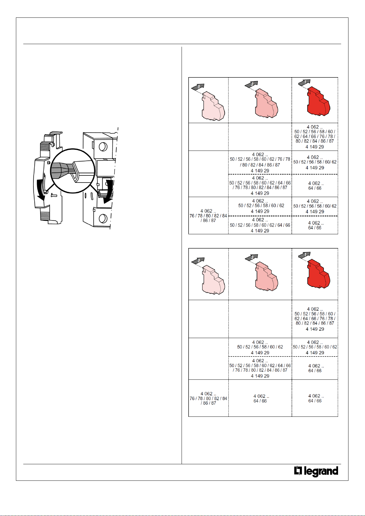
Assembling:
. On the left side of Legrand MCB, IS, RCBO or RCCB
. No tools are required. Clipped by mean of plastic clamps on the
associated device.
. Assembling products in OFF position
. The switching device of signalling auxiliaries must fit into the
housing of the handle of the associated device.
List of allowed associations (General rules):
Three auxiliaries maximum which:
- two signalling auxiliaries
(Cat. nos 4 062 50/52/56/58/60/62/64/66, 4 149 29).
- only one control auxiliary
(Cat. nos 4 062 76/78/80/82/84/86/87).
. If signalling and control auxiliaries are associated on the same
circuit breaker, the control auxiliary must be placed to the left of the
signal auxiliary (ref. 4 062 5x / 6x or 4 149 29).
List of allowed associations (Particular rules):
. With MCB’s 1,5 modules per pole width:
- if a remote tripping auxiliary (Cat. nos 4 062 76/78/80/82/84/86/
87) is already mounted on this kind of device, only 1 module
width signalling auxiliaries (Cat. nos. 4 062 64/66) can be added.
In this set up the ½ module signalling auxiliaries will not operate.
Nothing changes for the other modular references.
. With an isolating switch DX3-IS:
- only one signalling auxiliary CA type (Cat. nos 4 062
50/56/58/62/64/66) or CA+SD (Cat. n° 4 149 29).
. With a remote trip head isolating switch DX3-IS, three auxiliaries
maximum which:
- one or two signalling auxiliaries CA type Cat. nos 4 062
50/56/58/62/64/66) or CA+SD (Cat. n° 4 149 29).
- one control auxiliary (Cat nos 4 062 4 062 76/78/80/82/84/86/
87).
4. PREPARATION –CONNECTION
(continued)
Combination tables of the auxiliaries:
. For devices 1 module per pole width:
. For devices 1,5 modules per pole width:
Technical data sheet: F02334EN/02
Updated: 07/11/2018
Created: 20/07/2016
Page 3
3 / 14
EMS CX3 - Signalling Auxiliary Contact
(CA + SD)
Cat. N°: 4 149 29
4. PREPARATION –CONNECTION
(continued)
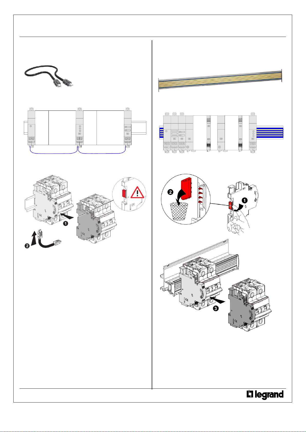
Data connection (EMS CX3 modules inter-connection):
. Via specific communication patch cords (cat. nos 4 149 07/08/09)
Allow data transmission between the different EMS CX3 modules.
This type of connection is recommended when there are few EMS
CX3 modules, distributed all over the enclosure.
Implementing: with this configuration, the plastic protection cover of
the backside communication ports on the EMS CX3 module must be
keep on.
4. PREPARATION –CONNECTION
(continued)
Data connection (EMS CX3 modules inter-connection)
(continued)
:
. Via specific communication rails (cat. nos 4 149 01/02/03).
. Allow data transmission between the different EMS CX3 modules.
This type of connection is recommended when there are several
EMS CX3 modules on the same DIN row.
Implementing: with this configuration, the plastic protection cover of
the backside communication ports on the EMS CX3 module must be
removed.
Technical data sheet: F02334EN/02
Updated: 07/11/2018
Created: 20/07/2016
Page 4
4 / 14
EMS CX3 - Signalling Auxiliary Contact
(CA + SD)
Cat. N°: 4 149 29
4. PREPARATION –CONNECTION
(continued)
Data connection (EMS CX3 modules inter-connection)
(continued)
:
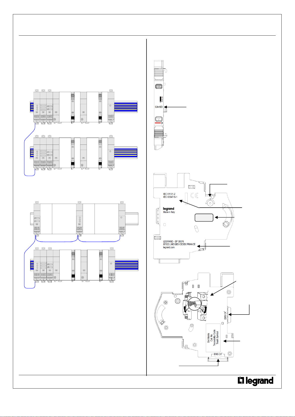
. Via a mix between specific communication patch cords and
communication rails in order to create a link between several rows
Two situations:
- Individually connected with communication rails.
The communication patch cord allows to connect two rows.
- Individually connected with communication patch cords &
communication rail.
The communication patch cords allow to connect EMS CX3
module on a row and to connect two rows.
5. GENERAL CHARACTERISTICS
Front face marking:
. By permanent ink pad printing (red line) and laser marking
Lateral side marking:
. By laser.
left side: Standard and programming information
right side: installing and traceability information
Technical data sheet: F02334EN/02
Updated: 07/11/2018
Created: 20/07/2016
Function name:
CA = auxiliary contact
SD = fault signalling
Legrand address
Indicates the presence
of the addressing
track-wheel
Assembling
information
Traceability
information
Data connection
with communication
rail
Data connection
with communication
patch cords
Standards
Label: to be removed
and kept if necessary
(ID and module info…
Page 5
5 / 14
EMS CX3 - Signalling Auxiliary Contact
(CA + SD)
Cat. N°: 4 149 29
5. GENERAL CHARACTERISTICS
(continued)
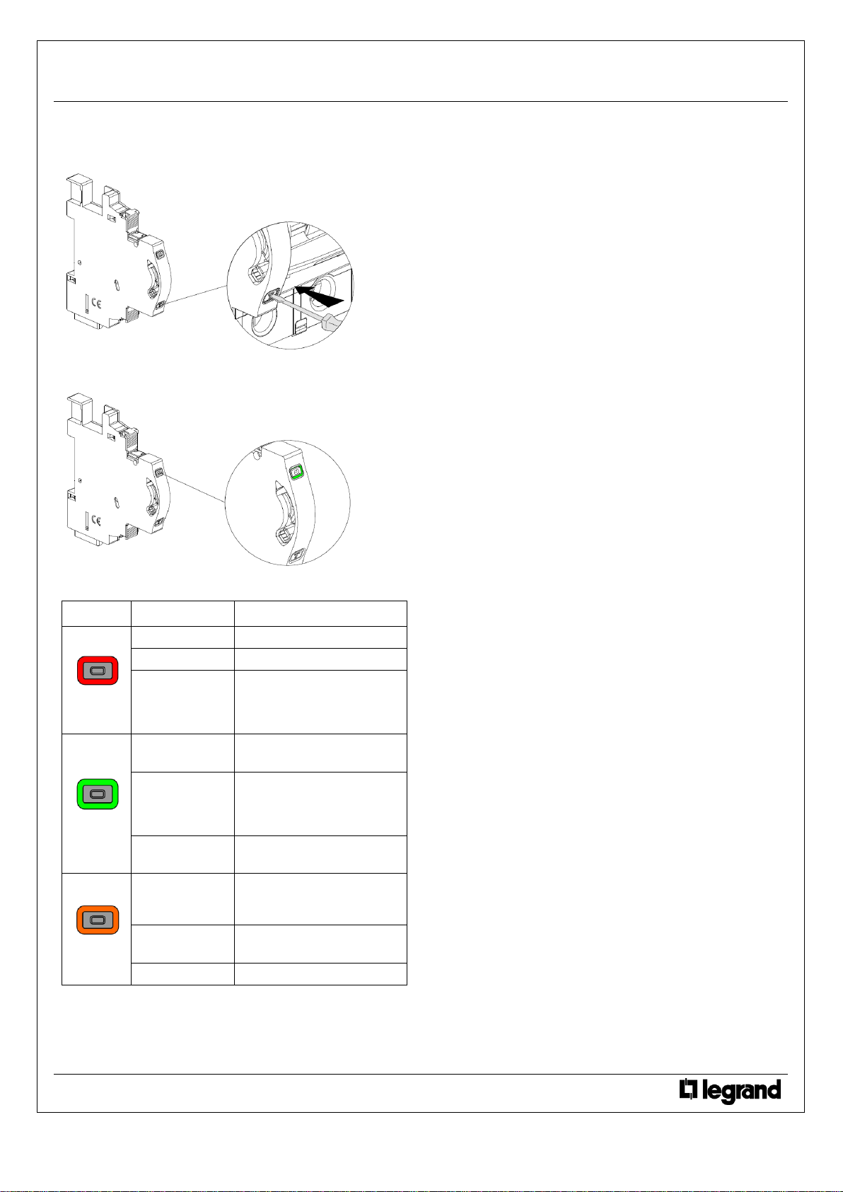
Test button:
. It allows to check the correct association between the module and the associated device.
Functions button:
. Front face button as several functions:
. Give information about the operating state on the module
Possible states:
Led colour
State
Meaning
red
Slow blinking
Error (e.g. addressing error)
Fast blinking
No function
Steady
(pressing the
multifunction button
longer than 20 sec.)
Total reset
[any firmware updates are
preserved]
green
Slow blinking
System process is running.
Wait until the Led turns steady
Fast blinking
(pressing the
multifunction button
for 10 sec.)
put in “Stand-by” the EMS CX3
module (no remote action and
communication available)
Steady
System OK, connection is
running
orange
Slow blinking
Creation of a link with “Link
Functionality” procedure
(see
next §)
Fast blinking
Device’s firmware update in
progress
Steady
No function
Technical data sheet: F02334EN/02
Updated: 07/11/2018
Created: 20/07/2016
Page 6

6 / 14
EMS CX3 - Signalling Auxiliary Contact
(CA + SD)
Cat. N°: 4 149 29
5. GENERAL CHARACTERISTICS
(continued)
Link Functionality:
. This function allows you to link two EMS CX3 modules to create automatic actions that, once programmed, can run independently without a
connection to a manager is needed.
The basic rule is the link between an event (circuit breaker that trip, a threshold exceeded, etc.) and an action accordingly (signalling, opening
of a circuit by motorized control or contactor, etc.).
Possible associations are:
Action module
Event
generator
Command:
4 149 32
State +
Command:
4 149 31
State:
4 149 30
Measure:
4 149 19/20/23
Only with the module configured
(locally or remotely) as shown:
State:
4 149 29/30
Is sufficient to configure the
module (locally or remotely) as
˝Slave˝
State + Command:
4 149 31
Is sufficient to configure the
module (locally or remotely) as
˝Slave˝
Note:
- association can only be of type 1 to 1 (1 event and 1 action).
- modules already associated cannot be used for other associations.
- all the configuring procedure will be done with the Configuration Software (available online for free).
[For more details refer to the Installation Manual
of EMS CX3 Configuration software]
Modules compatible with “Link Functionality” feature: firmware versions and production date:
Cat n°
Firmware version
Production date indicated on the label
sticked on the side of the module
4 149 19
ver. ≥ 2.0.1
date ≥ 18W29
4 149 20
ver. ≥ 2.0.1
date ≥ 18W49
4 149 23
ver. ≥ 2.0.1
date ≥ 18W49
4 149 29
ver. ≥ 2.0.1
date ≥ 18W49
4 149 30
ver. ≥ 2.0.2
date ≥ 18W32
4 149 31
ver. ≥ 2.0.6
date ≥ 18W45
4 149 32
ver. ≥ 3.0.2
date ≥ 18W39
4 149 36
ver. ≥ 2.0.4
date ≥ 18W38
4 149 37
ver. ≥ 2.0.4
date ≥ 18W43
4 149 40
ver. ≥ 3.0.8
date ≥ 18W34
Technical data sheet: F02334EN/02
Updated: 07/11/2018
Created: 20/07/2016
Page 7

7 / 14
EMS CX3 - Signalling Auxiliary Contact
(CA + SD)
Cat. N°: 4 149 29
5. GENERAL CHARACTERISTICS
(continued)
Insulation voltage:
. Ui = 400 V
Pollution degree:
. 2 according to IEC/EN 60898-1.
Overvoltage category:
. III
Dielectric strength:
. 2500 V
Tripping force:
. Between 1 and 1,5 Nm.
Mechanical endurance:
. These devices support the mechanical cycles of the associated
devices
. 20,000 manoeuvres
Plastic material:
. Self-extinguishing polycarbonate.
. Heat and fire resistant according to IEC/EN 60695-2-12, glow-wire
test at 960°C.
. Classification UL 94 / IECEN 60695-11-10: V1
Ambient operating temperature:
. Min. = -25°C. Max. = +70°C
Ambient storage temperature:
. Min. = -40°C. Max. = +70°C
Protection Index:
. Protection index of terminals against direct contacts:
IP2X (IEC/EN 60529).
. Protection index of terminals against solid and liquid bodies (wired
device): IP 20 (IEC/EN 60529).
. Protection index of the front face against solid and liquid bodies: IP
40 (IEC/EN 60529).
. Class II, front panel with faceplate.
Average weight per device:
. 0,032 kg.
Volume when packed:
. 0,21 dm
3
.
Consumption:
. Values at 12 VDC
0,236 W
19,7 mA
Technical data sheet: F02334EN/02
Updated: 07/11/2018
Created: 20/07/2016
Page 8

8 / 14
EMS CX3 - Signalling Auxiliary Contact
(CA + SD)
Cat. N°: 4 149 29
6. SYSTEM ARCHITECTURES
The EMS CX3 is a polyvalent system and, according to the needs of the customer, can be set up and/or used as “Stand-alone” or “Supervised”
system. Based on this choice the configuration and addressing methods are different.
Four possible architectures are provided:
6.1 Stand-alone system
6.1.1 with local addressing (through the track wheel)
6.1.2 with remote addressing (through a computer)
6.2 Supervised (Computer Supervisory System)
6.2.1 with local addressing
6.2.2 with remote addressing
6.1 Stand-alone system
. Stand-alone = autonomous system. To be used by the end-user if it is not necessary to have a computer for the supervision outside the
envelope. Everything can be managed on site.
6.1.1 Stand-alone system with local addressing (through the track wheel)
Local addressing advantages:
- No configuration software needed to set-up the installation
- It is not necessary to use a computer to manage settings (configurations, test, ...) and to use the system (visualize and be alerted,
...). Everything can be done through the Mini configuration module (local display, cat. no 4 149 36/37).
[Refer to the technical sheet
dedicated to this module for details]
.
- No communication Interfaces or gateways are required.
- Installation can be done without the intervention of a System Integrator
Programming procedure:
. For EMS CX3 modules which need some: mandatory through to lateral DIP-switch of each EMS CX3 modules (see § ”Module configuration”)
Addressing procedure:
. For all EMS CX3 modules: mandatory through the track wheel located on the top upper face of each EMS CX3 modules
. Marked from 0 to 9 in order to locally define the Modbus address of the EMS CX3 modules
Consequences of the local addressing mode (through the track wheel):
. Each device of the system must be addressed.
. Addresses available: from 1 to 9
. Address 0 not permitted
. It is possible to assign to several devices the same address with the purpose of grouping different functions, because they are related to the
same electrical circuit. For example, it is possible to assign the same address to a signalling auxiliary module (cat. no 4 149 29), a universal
control module (cat. no 4 149 32), a measuring module, and so on. In this way on the EMS CX3 mini configuration module (local display) the
grouped function will be displayed as a unique “device” with all grouped functions.
[Refer to the schemes hereunder]
Note for the mini configuration module (local display)
. It is possible to assign it the same address as another EMS CX3 through the programming menu of the device
. The mini configuration module can be placed everywhere in the EMS CX3 bus
Technical data sheet: F02334EN/02
Updated: 07/11/2018
Created: 20/07/2016
Page 9

9 / 14
EMS CX3 - Signalling Auxiliary Contact
(CA + SD)
Cat. N°: 4 149 29
6. SYSTEM ARCHITECTURES
6.1 Stand-alone system
(continued)
6.1.2 Stand-alone system with remote addressing (through a computer)
Remote addressing advantages:
- Whole configuration (addresses and functions) can be set up through the EMS Configuration software
- Configuration software available for free
- Automatic detection of the EMS CX
3
modules installed in the system (characteristics, functions, configuration...)
- Increased settings possibilities: load shedding function
- Increased addressing: up to 30 Modbus addresses in a system
Programming procedure:
. For EMS CX3 modules which need some: possible through the lateral DIP-switch of each EMS CX3 modules (see § “Module configuration”).
Addressing procedure:
. It is not necessary to address the EMS CX3 modules. The track wheel must be left in default position “0”.
. All the addressing/configuring procedure will be done with the Configuration Software (available online for free)
. With remote addressing, the software does the automatic detection of modules installed in the system, but the supervision is not possible until
the user assigns the remote address and all the characteristics to each module.
Note: it is mandatory to connect the computer to the mini configuration module with an USB-micro USB cable.
[For more details, refer to User
Manual Document]
Technical data sheet: F02334EN/02
Updated: 07/11/2018
Created: 20/07/2016
Page 10

10 / 14
EMS CX3 - Signalling Auxiliary Contact
(CA + SD)
Cat. N°: 4 149 29
6. SYSTEM ARCHITECTURES
6.1 Stand-alone system
(continued)
6.1.2 Stand-alone system with remote addressing (through a computer)
(continued)
Consequences for the system architecture:
- for 1 mini configuration module (cat. no 4 149 36/37)
o up to 30 EMS CX
3
modules (eg. 30 devices grouped per functions with addresses from1 to 30)
It is possible to assign to several devices the same address with the purpose of grouping different functions, because they are related to the
same electrical circuit. For example, it is possible to assign the same address to a signalling auxiliary module (cat. no 4 149 29), a universal
control module (cat. no 4 149 32), a measuring module, and so on. In this way on the EMS CX3 display or in a supervision system the grouped
function will be displayed as a unique “device” with all grouped functions.
[Refer to the schemes here under]
Note for the mini configuration module (local display)
. It is possible to assign it the same address as another EMS CX3
. The mini configuration module can be placed everywhere in the EMS CX3 bus
6.2 Supervised system (Computer Supervisory System)
. Supervised system = System to be used through a Computer Supervisory System to remotely read data from the EMS CX3 devices and/or do
operations on these devices (e.g. commands of a motor driven or contactor ...).
6.2.1 Supervised system with local addressing (through the track wheel)
Local addressing advantages:
- No configuration software needed to set-up the installation
- Installation can be done without the intervention of a System Integrator
Programming procedure:
. For EMS CX3 modules which need some: mandatory through to lateral DIP-switch of each EMS CX3 modules (see § “Module configuration”)
Addressing procedure:
. For all EMS CX3 modules: mandatory through the track wheel located on the top upper face of each EMS CX3 modules
. Marked from 0 to 9 in order to locally define the Modbus address to EMS CX3 modules
In this system the Modbus address of an EMS CX3 module device or group of modules (several functions) is obtained considering the address
of the interface Modbus/EMS CX3 Interface as tenth and the address of a device or group of function as unit (e.g. Interface address 1 = 10
address of module n°5 = Modbus address 15)
Technical data sheet: F02334EN/02
Updated: 07/11/2018
Created: 20/07/2016
Page 11

11 / 14
EMS CX3 - Signalling Auxiliary Contact
(CA + SD)
Cat. N°: 4 149 29
6. SYSTEM ARCHITECTURES
(continued)
6.2 Supervised system (Computer Supervisory System)
(continued)
6.2.1 Supervised system with local addressing (through the track wheel)
(continued)
Consequences of the local addressing mode (through the track wheel):
. Each device of the system must be addressed.
. Addresses available: from 1 to 9
. Address 0 not permitted
It is possible to assign to several devices the same address with the purpose of grouping different functions, because they are related to the
same electrical circuit. For example, it is possible to assign the same address to a signalling auxiliary module (cat. no 4 149 29), a universal
control module (cat. no 4 149 32), a measuring module, and so on. In this way on the EMS CX3 display or in a supervision system the grouped
function will be displayed as a unique “device” with all grouped functions.
[Refer to the scheme hereunder]
Note: In this configuration the Modbus address of an EMS CX3 module device or group of modules (several functions) is obtained considering
the address of the interface Modbus/EMS CX3 Interface as tenth and the address of a device or group of function as unit (e.g. Interface address
1 = 10 and device address = 5 Modbus address = 15)
Consequences for the system architecture:
- for 1 IP/Modbus gateway (cat. no 0 046 89):
o up to 81 Modbus address
o mandatory limit of max. 9 Modbus/EMS CX
3
interfaces or max. 1000 m of Modbus cable (cable Belden 9842, Belden 3106A or
equivalent).
- for 1 Modbus/EMS CX
3
Interface (cat. no 4 149 40):
o up to 30 EMS CX
3
modules (ex. 30 devices grouped per functions with addresses from1 to 9)
Note: with local addressing, the Modbus/EMS CX3 interface, does the automatic detection of modules (characteristics, functions,
configuration...)
Technical data sheet: F02334EN/02
Updated: 07/11/2018
Created: 20/07/2016
Cat. no 0 046 89
Page 12

12 / 14
EMS CX3 - Signalling Auxiliary Contact
(CA + SD)
Cat. N°: 4 149 29
6. SYSTEM ARCHITECTURES
(continued)
6.2 Supervised system (Computer Supervisory System)
(continued)
6.2.2 Supervised system with remote addressing (through a computer)
Remote addressing advantages:
- Whole of configuration (addresses and functions) can be done a remotely through the EMS Configuration software
- Configuration software available for free
- Automatic detection of the EMS CX
3
modules installed in the system (characteristics, functions, configuration...)
- Increased settings possibilities: load shedding function
- Increased addressing: up to 32 Modbus/EMS CX
3
interfaces
- Increased addressing: up to 247 Modbus addresses in a system
Programming procedure:
. For EMS CX3 modules which need some: possible through the lateral DIP-switch of each EMS CX3 modules (see § “Module configuration”).
Note: via the configuration software it is possible to assign all the functions and characteristics of each EMS CX3 module
Addressing procedure:
. It is not necessary to address the EMS CX3 modules. The track wheel must be left in default position “0”.
. All the addressing/configuring procedure will be done with the Configuration Software (available online for free)
. With remote addressing, the software does the automatic detection of modules installed in the system, but the supervision is not possible until
the user assigns the remote address and all the characteristics to each module.
Note: it is mandatory to connect the computer to the different Modbus/EMS CX3 interface with an USB-micro USB cable (one interface at a
time).
[For more details, refer to the User Manual Document]
Technical data sheet: F02334EN/02
Updated: 07/11/2018
Created: 20/07/2016
Page 13

13 / 14
EMS CX3 - Signalling Auxiliary Contact
(CA + SD)
Cat. N°: 4 149 29
6. SYSTEM ARCHITECTURES
(continued)
6.2 Supervised system (Computer Supervisory System)
(continued)
6.2.2 Supervised system with remote addressing (through a computer)
(continued)
Consequences for the system architecture:
- for 1 IP/Modbus gateway (cat. no 0 046 89):
o up to 247 Modbus address
o Because of Modbus: mandatory limit of max. 32 Modbus/EMS CX
3
interfaces or max. 1000 m of Modbus cable (cable Belden 9842,
Belden 3106A or equivalent).
- for1 Modbus/EMS CX
3
Interface (cat. no 4 149 40):
o up to 30 EMS CX
3
modules or grouped modules (e.g. 30 devices grouped per functions with addresses from1 to 30)
It is possible to assign to several devices the same address with the purpose of grouping different functions, because they are related to the
same electrical circuit. For example, it is possible to assign the same address to a signalling auxiliary module (cat. no 4 149 29), a universal
control module (cat. no 4 149 32), a measuring module, and so on. In this way on the EMS CX3 display or in a supervision system the grouped
function will be displayed as a unique “device” with all grouped functions.
[Refer to the scheme up here]
Technical data sheet: F02334EN/02
Updated: 07/11/2018
Created: 20/07/2016
Cat. no 0 046 89
Page 14

14 / 14
EMS CX3 - Signalling Auxiliary Contact
(CA + SD)
Cat. N°: 4 149 29
7. COMPLIANCE AND APPROVALS
Compliance to standards:
. Compliance with Directive on electromagnetic compatibility (EMC)
n° 2014/30/EU
. Compliance with low voltage directive n° 2014/35/EU.
. Electromagnetic Compatibility:
IEC/EN 61131-2
IEC/EN 60947-5-1
Environment respect - Compliance with EU directives:
. Compliance with Directive 2011/65/EU as amended by Directive
2015/863 (RoHS 2) on the restriction of the use of certain
hazardous substances in electrical and electronic equipment.
. Compliance with REACH regulation (1907/2006): at the date of the
publication of this document no element of the SVHC substance list
(updated on 27/06/2018) is present in these products.
. WEEE directive (2012/19/EU): the sale of this product is subject to
a contribution to eco-organisations in each country responsible for
managing end-of-life products in the field of application of the
European Waste Electronic and Electrical Equipment Directive.
Plastic materials:
. Halogens-free plastic materials.
. Marking of parts according to ISO 11469 and ISO 1043.
Packaging:
. Design and manufacture of packaging compliant to decree 98-638
of the 20/07/98 and also to directive 94/62/CE.
Environmental profile:
. PEP document available
Installation software:
. XL PRO3.
Technical data sheet: F02334EN/02
Updated: 07/11/2018
Created: 20/07/2016
 Loading...