

Page 1
Plugmold 2000 Aluminum
Legrand/Wiremold electrical systems conform to and should be properly
grounded in compliance with requirements of the current National
Electrical Code or codes administered by local authorities.
All electrical products may present a possible shock or fire
hazard if improperly installed or used. Legrand/Wiremold electrical
products may bear the mark of a Nationally Recognized Testing
Laboratory (NRTL) and should be installed in conformance with current
local and/or the National Electrical Code.
Plugmold 2000TR Aluminum
I N S T A L L A T I O N I N S T R U C T I O N S
Installation Instruction No.: 1 009 949 – February 2011
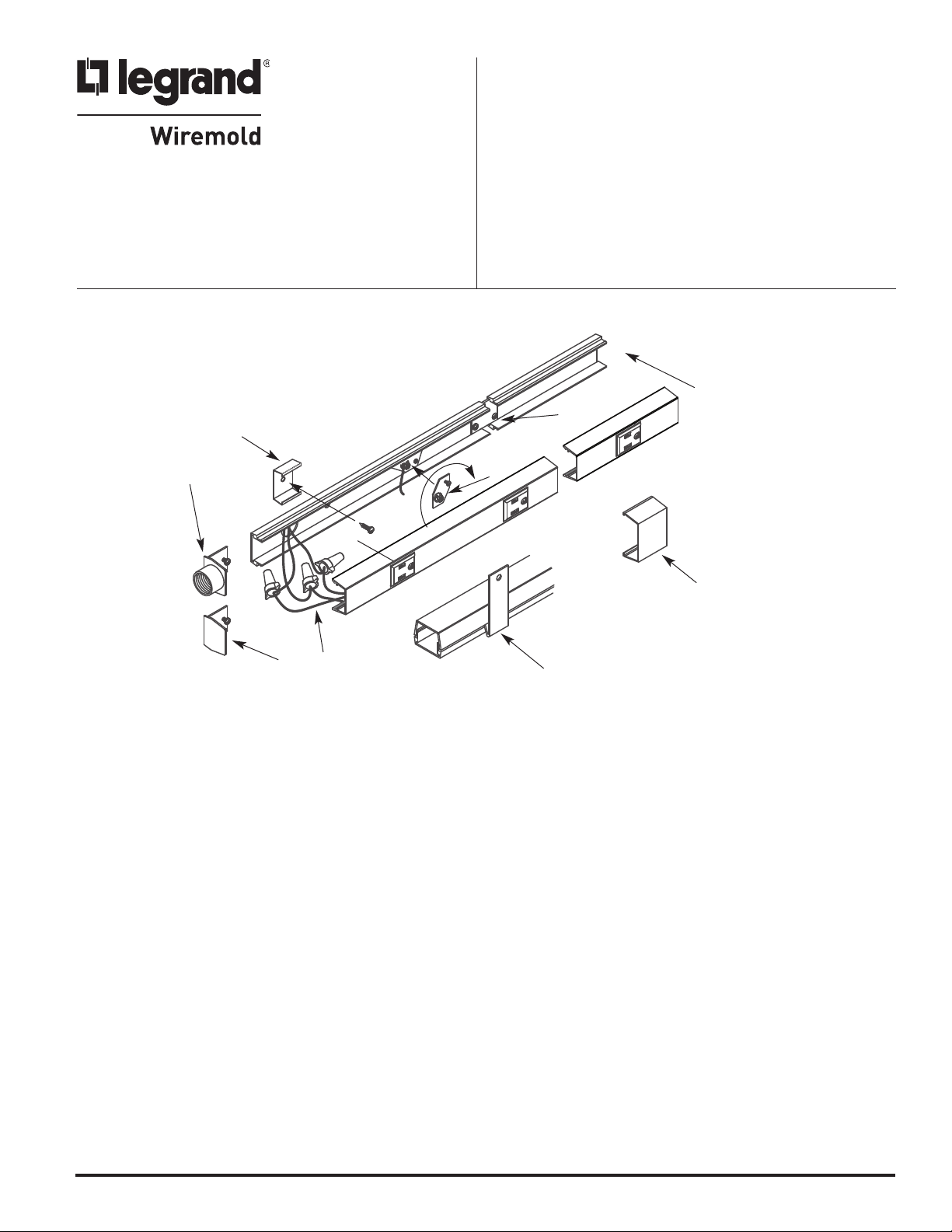
AL2000 SYSTEM PRODUCT APPLICATIONS
2
1
5
4
IMPORTANT: Please read all instructions
before beginning.
6
2
3
7
8
TO INSTALL:
1. Bring Feed into Base
a. Remove appropriate 1/2" trade size entrance knockout in base, or attach Feed End Fitting (AL2010A).
2. Install Base Section on Surface
a. Attach base section on mounting surface using AL2003 Spring Mounting Clips, or by drilling 9/32” holes in the base and use #8
set screws. Ensure holes are free from burrs.
b. If required, cut base to length and carefully debur any cut ends before mounting. If cuts have been made to the base, center the
cover section over the mounted base. Locate, mark and cut the cover ends. If the edge of any receptacle falls closer than 1 1/2"
[38mm] from the end of the unit, that receptacle must be cut out to allow sufficient space for the installation of an end fitting.
c. Connect multiple sections together using coupler (AL2001). To install, slide coupling plate into both base sections, center on joint
and tighten locking screws.
d. To install around corners, use appropriate elbows, (AL2011 - 90° Flat Elbow), (AL2017 – Internal Elbow), or (AL2017 - External Elbow)
3. Install Ground Adapter
a. Use Ground Adapter (AL2009) provided to secure ground connection. To relocate, loosen set screw and twist counter clockwise.
Position in between receptacles (to avoid interference) and assemble in reverse order.
4. Install Blank End Fitting (AL2010B)
a. At end of base raceway run, slide blank end fitting in last base sections and secure in place by tightening screw.
5. Connect wired section to feed
a. Connect feed wires to wired raceway sections. It is recommended to stagger connection points to allow room for all connections.
6. Snap raceway cover onto base
a. If necessary, snap receptacle harness into cover making sure to line up receptacle faces with pre-punched holes in the raceway cover.
b. Engage lower edge of cover over the edge of the base. Starting at one end and progressing along the unit, snap in upper edge
of the cover with the heel of the hand. Ensure that wires are pushed completely into the base before assembling the cover to
avoid pinching the wires.
7. Snap on cover clip to cover joint seams where lengths of covers come together.
8. To remove cover, insert removal tool into groove, push down and twist.
NOTE: All mounting methods must result in flush interior surface.
Page 2

AL2000 RACEWAY WIRE FILL CAPACITIES FOR POWER
MAXIMUM CROSS SECTION
8 sq. in.
.
20.3mm]
.1 sq. in.
1/8"
1
29mm]
[
NOTE: Raceway may be configured in single or
1
27mm]
[
7/16"
1
37mm]
[
multiple channels to accommodate power
or communications wiring.
[
AL2000 RACEWAY WIRE FILL CAPACITIES FOR POWER
POWER WIRING 10 AWG 8
WITHOUT DEVICE 12 AWG 12
1.1 sq. in. cross section 14 AWG 24
POWER WIRING AWG 10 AWG 3
WITH DEVICE 12 AWG 6
515 amp devices 14 AWG 8
.8 sq. in. cross section
AL2003 Mounting Clip AL2006 Cover Clip
WIRE TYPE THHN/THWN
Use for external support of raceway. To install attach
AL2003 to mounting surface with screws. Snap
raceway base into AL2003.
AL2010A Feed End Fitting
AL2010B Blank End Fitting
At end of AL2000B base raceway run, slide AL2000A or
AL2000B fitting in last base section. Secure in place by
tightening screw.
le
c
pta
e
c
Re
und
d Gro
te
a
ol
s
I
line
n-
olated
G I
Gro
G Ta
I
und Re
mper-
eptac
c
Re
sis
tant I
le
n-line
AL2043I
AL2043TR
Is
To close any gaps. That occur from field cutting, snap
AL2006 Cover Clip over joints, where two adjoining
pieces come together.
AL2043 In-line Receptacle
AL2043TR Tamper-Resistant In-line Receptacle
For AL2043 Series Two 15A, 120V U-ground factory prewired
receptacles. To install slide coupler into grooves of AL2000B
end base raceway and push sections together. Connect
wires, tighten. Screws and snap in cover.
AL2040A In-line Single Pole Switch
For AL2043IG Series Two 15A, 120V Isolated ground factory
prewired receptacles. To install slide coupler into grooves
of AL2000B base raceway and push sections together.
Connect wires, tighten screws and snap in cover.
Single Pole Switch 15A. 120V. To Install slide coupler into
groove of AL2400B base raceway and push sections together.
Tighten screws and snap in cover.
Page 3

L2044 Series
AL2038 Series
Round Fixture Box
TO INSTALL:
1. Attach back plate to 2x4 outlet utility box or mounting surface.
2. If back plate is not attached to box, use cover to close opening.
3. 1/2" or 3/4" conduit connections may be connected to back cover.
4. Slide AL2000B base raceway into slot of back plate. Tighten set
screws to secure connections and for ground continuity.
A
Deep Device Box
5. Twist out KOs in cover section where raceway enters.
Attach cover with screws.
6. Attach device ( if required) to cover section.
7. Install standard cover plate.
L2047 Series Shallow Switch &
A
Receptacle Box
AL2011 90° Flat Elbow AL2017 Internal Elbow
At 90° turn on same surface, position AL2011 Flat Elbow at end
of AL200B base. Position next base section onto other end of
AL2011. Center coupling over base joints and over base joints
and tighten screws. Install fitting cover after wiring.
AL2015 Tee Elbow
AL2015 Tee Fitting, position fitting at end of AL2000B base.
Install other base section to other end of fitting. Center
couplings on joints and tighten screws. Install fitting
cover after wiring.
AL2416 Cross Elbow
Install AL2017 to raceway base BEFORE mounting raceway
base. Fasten section to surface joints, tighten set screws.
Center coupling over base and tighten screws. Install
fitting cover after wiring.
AL2018 External Elbow
At 90° outside corner, position AL2018 External Elbow at end
of joints and tighten screws. Install fitting cover after wiring.
AL2000WC Wire Clip
AL2416 Cross Elbow, position fitting at end of AL2000B base.
Install other base sections to other ends of the fitting.
Center couplings on joints tighten screws. Install
cover fitting after wiring.
For retaining wires in long raceway run, Snap-in AL2000 WC
Wire Clip approximately 30" apart into AL2000B base.
Page 4

AL2000B Base
48"
[1219mm]
L2001 Coupling
A
To attach AL2000B base sections to mounting surface, drill
9/32" holes in the base (approx. 48" o.c.). Fasten base with
8 flathead head screws.
#
AL2051H Box Adapter
Use for feed raceway from existing wall outlet box. To install,
attach adapter to outlet box with two screws. This system is
designed with capacity for additional feed or circuitry conductors.
t AL2000B base section butt joints, slide AL2001 Coupling
A
into first base section mount next base to surface. Center
coupling on joints. Tighten locking screws.
AL2009 Ground Clamp
Position AL 2009 Ground Clamp into rib in AL2000B raceway
base. Tighten locking screw. Attach ground wire using brass
cup washer and green hex nut to ground lug.
© Copyright 2011 Legrand/Wiremold All Rights Reserved
WIREMOLD
U.S. and International:
60 Woodlawn Street • West Hartford, CT 06110
1-800-621-0049 • FAX 860-232-2062 • Outside U.S.: 860-233-6251
Canada:
570 Applewood Crescent • Vaughan, Ontario L4K 4B4
1-800-723-5175 • FAX 905-738-9721
1 009 949 0211
 Loading...