

Page 1

Line Interactive Sinewave UPS
1.1KVA | 1.5KVA | 2KVA | 3KVA Models
Uninterruptible Power Supply System
User Manual
I-00886 Rev A
Page 2

2
Table of Contents
Important Safety Warnings ......................................................................................................3
Transportation and Storage ................................................................................................................................................. 3
Preparation ......................................................................................................................................................................... 3
Installation .......................................................................................................................................................................... 3
Operation ............................................................................................................................................................................ 4
Maintenance, Service and Faults ........................................................................................................................................ 4
Avertissements de sécurité importants ....................................................................................5
Transport et stockage .......................................................................................................................................................... 5
Préparation ......................................................................................................................................................................... 5
Installation .......................................................................................................................................................................... 6
Fonctionnement .................................................................................................................................................................. 6
Maintenance, Service et Défauts ........................................................................................................................................ 7
1. Installation and Setup ..........................................................................................................9
Unpacking and Inspection ................................................................................................................................................... 9
Rear Panel ......................................................................................................................................................................... 10
Operating Principle ........................................................................................................................................................... 11
Installing The UPS .............................................................................................................................................................. 11
Setting Up the UPS ............................................................................................................................................................ 13
Battery Replacement ......................................................................................................................................................... 15
Replacement Battery Assembly ........................................................................................................................................ 16
2. Operations .......................................................................................................................... 18
Button Operations ............................................................................................................................................................. 18
LCD Panel .......................................................................................................................................................................... 19
Audible Alarms .................................................................................................................................................................. 20
LCD Panel Index ................................................................................................................................................................. 21
Operating Mode Descriptions ........................................................................................................................................... 21
UPS Settings ...................................................................................................................................................................... 22
Fault Reference Codes ....................................................................................................................................................... 25
Warning Indicators ............................................................................................................................................................ 25
4. Troubleshooting ................................................................................................................. 26
5. Maintenance and Storage ................................................................................................... 27
Maintenance ..................................................................................................................................................................... 27
Storage .............................................................................................................................................................................. 27
6. Specifications ..................................................................................................................... 28
Input .................................................................................................................................................................................. 28
Output ............................................................................................................................................................................... 28
Efficiency ........................................................................................................................................................................... 28
Battery ............................................................................................................................................................................... 28
Protection.......................................................................................................................................................................... 28
Alarm ................................................................................................................................................................................. 29
Physical .............................................................................................................................................................................. 29
Environment ...................................................................................................................................................................... 29
Management ..................................................................................................................................................................... 29
Expandable Battery Box Specification ............................................................................................................................... 30
Page 3

3
Important Safety Warnings
Comply with all warnings and operating instructions in this manual and save it for future reference. Do not
operate this unit before carefully reading through all safety information and operating instructions.
Transportation and Storage
Transport the UPS system only in the original package to protect against shock and impact.
The UPS must be stored in a ventilated and dry room.
Preparation
Condensation may occur if the UPS system is moved directly from cold to warm environments. The
UPS system must be absolutely dry before being installed. Please allow at least two hours for the UPS
system to adjust to the environment.
Do not install the UPS system near water or in damp environments.
Do not install the UPS system where it would be exposed to direct sunlight or near a heater.
Do not block ventilation holes on the UPS housing.
Installation
Do not connect appliances or devices to the UPS output sockets or terminal that would over load the
UPS.
Place cables in such a way that no one can step on or trip over them.
Do not connect domestic appliances such as hair dryers to UPS output sockets.
Connect the UPS system only to a grounded, shockproof outlet, which must be easily accessible and
close to the UPS system.
Use only a VDE-tested, CE-marked (or UL-marked for 100/110/115/120/127 Vac models) mains cable
(e.g. the mains cable of your computer) to connect the UPS system to the building wiring outlet (shockproof
outlet).
Use only VDE-tested, CE-marked (or UL-marked for 100/110/115/120/127 Vac models) power cables
to connect the loads to the UPS system.
When installing the equipment, ensure that the sum of the leakage current of the UPS and the
connected devices does not exceed 3.5mA.
Temperature Rating: Units are considered acceptable for use in a maximum ambient environment of
104°F (40°C).
For Pluggable Equipment: The socket-outlet shall be installed near the equipment and shall be easily
accessible.
The unit is heavy. Lifting the unit requires a minimum of two people.
Page 4

4
Operation
Do not disconnect the ground conductor cable on the UPS or the building wiring terminals at any time
since this would cancel the protective earth of the UPS system and of all connected loads.
The UPS system features its own, internal current source (batteries), therefore, the UPS output
sockets or output terminal blocks may be electrically live even if the UPS system is not connected to the
building wiring outlet.
In order to fully disconnect the UPS system, first press the “OFF” button, and then disconnect the
mains.
Ensure that no liquid or other foreign objects can enter into the UPS system.
The EPO, RS-232 and USB circuits are an IEC 60950-1 safety extra low voltage (SELV) circuit. This
circuit must be separated from any hazardous voltage circuits by reinforced insulation.
Maintenance, Service and Faults
The UPS system operates with hazardous voltages. Repairs may be carried out only by qualified
maintenance personnel.
Risk of electric shock. Even after the unit is disconnected from the mains (building wiring outlet);
components inside the UPS system are still connected to the battery and are electrically live and dangerous.
Before performing any service and/or maintenance, disconnect the batteries and verify that no
current is present and no hazardous voltage exists on the terminals of the high capability capacitor, such as
BUS-capacitors.
Only persons are adequately familiar with batteries and with the required precautionary measures
may replace batteries and supervise operations. Unauthorized persons must be kept well away from the
batteries.
Risk of electric shock. The battery circuit is not isolated from the input voltage. Hazardous voltages
may occur between the battery terminals and the ground. Before touching, please verify that no voltage is
present.
Do not dispose of batteries in a fire. The batteries may explode.
Do not open or mutilate batteries. Released electrolyte is harmful to the skin and eyes. It may be
toxic.
Batteries may cause electric shock and have a high short-circuit current. Please take the
precautionary measures specified below and any other measures necessary when working with batteries:
• Remove watches, rings, or other metal objects.
• Use tools with insulated handles.
• Wear rubber gloves and boots.
• Do not lay tools or metal parts on top of batteries.
• Disconnect charging source and load prior to installing or maintaining the battery.
• Remove battery grounds during installation and maintenance to reduce likelihood of shock. Remove the
connection from ground if any part of the battery is determined to be grounded.
Page 5

5
When changing batteries, install the same number and same type of batteries or battery packs.
For UPS with internally mounted battery:
• Instructions shall have sufficient information to enable the replacement of the battery with a suitable
manufacturer and catalogue number.
• Safety instructions to allow access by Service Personnel shall be stated in the installation/service
handbook.
• If batteries are to be installed by Service Personnel, instructions for interconnections, including terminal
torque, shall be provided.
Do not attempt to dispose of batteries by burning them. This could cause an explosion.
Do not open or destroy batteries. Escaping electrolyte can cause injury to the skin and eyes. It may
be toxic.
Only replace the fuse with the same type and amperage to avoid fire hazards.
Do not disassemble the UPS system.
This equipment has been tested and found to comply with the limits for a Class A digital device,
pursuant to part 15 of the FCC Rules. These limits are designed to provide reasonable protection against
harmful interference when the equipment is operated in a commercial environment. This equipment
generates, uses, and can radiate radio frequency energy and, if not installed and used in accordance with
the instruction manual, may cause harmful interference to radio communications. Operation of this
equipment in a residential area is likely to cause harmful interference in which case the user will be required
to correct the interference at his own expense.
Changes or modifications not expressly approved by the party responsible for compliance could void
the user's authority to operate the equipment.
This is a product for commercial and industrial applications. In second environment installations,
restrictions or additional measures may be needed to prevent disturbances.
Avertissements de sécurité importants
Respectez tous les avertissements et consignes d'utilisation de ce manuel et conservez-le pour référence
ultérieure. Ne faites pas fonctionner cet appareil avant de lire attentivement toutes les informations de
sécurité et les instructions d'utilisation.
Transport et stockage
Transportez le système UPS uniquement dans son emballage d'origine pour le protéger contre les
chocs.
L'onduleur doit être stocké dans une pièce ventilée et sèche.
Préparation
De la condensation peut se produire si le système UPS est directement déplacé d'un environnement
froid à un environnement chaud. Le système UPS doit être absolument sec avant d'être installé. Veuillez
prévoir au moins deux heures pour que le système d'ASI s'adapte à l'environnement.
N'installez pas l'onduleur à proximité d'eau ou dans un environnement humide.
Page 6
6
N'installez pas le système UPS à un endroit exposé à la lumière directe du soleil ou à proximité d'un
appareil de chauffage.
Ne bloquez pas les trous de ventilation sur le boîtier de l'onduleur.
Installation
Ne connectez pas de périphériques à la sortie de l'onduleur ou à un terminal susceptible de
surcharger l'onduleur.
Placez les câbles de manière à ce que personne ne puisse marcher dessus ou trébucher dessus.
Ne connectez pas d'appareils domestiques tels que des sèche-cheveux aux prises de sortie de l'ASI.
Ne connectez le système ASI qu'à une prise de terre protégée contre les chocs, qui doit être
facilement accessible et proche du système ASI.
Utilisez uniquement un câble d'alimentation certifié VDE, marqué CE (par exemple, le câble
d'alimentation de votre ordinateur) pour connecter le système UPS au câblage du bâtiment sortie (sortie
antichoc).
Utilisez uniquement des câbles d'alimentation VDE, marqués CE pour connecter les charges au
système UPS.
Lors de l'installation de l'équipement, assurez-vous que la somme du courant de fuite de l'onduleur et
des périphériques connectés ne dépasse pas 3.5 mA.
Température nominale: Les unités sont considérées acceptables pour une utilisation dans un
environnement ambiant maximal de 40°C (104°F).
Pour les équipements enfichables: La prise de courant doit être installée près de l'équipement et doit
être facilement accessible.
L'unité est lourde. Le levage de l'unité nécessite un minimum de deux personnes.
Fonctionnement
Ne déconnectez pas le câble du conducteur de mise à la terre de l'onduleur ou des bornes de câblage
du bâtiment car cela annulerait la mise à la terre de protection de l'onduleur et de toutes les charges
connectées.
Le système ASI dispose de sa propre source de courant interne (batteries). Par conséquent, les prises
de sortie ou les borniers de sortie de l'ASI peuvent être sous tension même si le système ASI n'est pas
connecté à la sortie du bâtiment.
Pour déconnecter complètement le système UPS, appuyez d'abord sur le bouton "OFF", puis
débranchez le secteur.
Assurez-vous qu'aucun liquide ou autre corps étranger ne puisse pénétrer dans le système ASI.
Les circuits EPO, RS-232 et USB sont des circuits de très basse tension de sécurité (TBTS) CEI
60950-1. Ce circuit doit être séparé de tout circuit de tension dangereux par une isolation renforcée.
Page 7

7
Maintenance, Service et Défauts
Le système UPS fonctionne avec des tensions dangereuses. Les réparations ne peuvent être
effectuées que par du personnel de maintenance qualifié.
Risque de choc electrique. Même après que l'appareil est déconnecté du secteur (prise de câblage du
bâtiment); les composants à l'intérieur du système UPS sont toujours connectés à la batterie et sont sous
tension et dangereux.
Avant d'effectuer toute opération de maintenance, déconnectez les batteries et vérifiez qu'il n'y a pas
de courant et qu'aucune tension dangereuse n'existe sur les bornes du condensateur haute capacité, telles
que les condensateurs BUS.
Seules des personnes connaissent bien les batteries et, avec les mesures de précaution requises,
peuvent les remplacer et superviser les opérations. Les personnes non autorisées doivent être tenues à
l'écart des batteries.
Risque de choc electrique. Le circuit de la batterie n'est pas isolé de la tension d'entrée. Des tensions
dangereuses peuvent se produire entre les bornes de la batterie et le sol. Avant de toucher, vérifiez s'il n'y a
pas de tension.
Ne jetez pas les piles dans un feu. Les piles peuvent exploser.
N'ouvrez pas et ne mutilez pas les piles. L'électrolyte libéré est nocif pour la peau et les yeux. Cela
peut être toxique.
Les batteries peuvent provoquer un choc électrique et un courant de court-circuit élevé. Veuillez
prendre les mesures de précaution suivantes et toutes les autres mesures nécessaires lorsque vous travaillez
avec des batteries:
• Retirez les montres, bagues ou autres objets métalliques.
• Utilisez des outils avec des poignées isolées.
• Portez des gants et des bottes en caoutchouc.
• Ne posez pas d'outils ou de pièces métalliques sur les batteries.
• Débranchez la source de charge avant d'installer ou de maintenir la batterie.
• Retirez les masses de la batterie pendant l'installation et la maintenance afin de réduire les risques de
choc. Retirez la connexion de la masse si une partie de la batterie est déterminée pour être mise à la
terre.
Lorsque vous changez les piles, installez le même numéro et le même type de piles ou de batteries.
Pour onduleur avec batterie interne:
• Les instructions doivent contenir suffisamment d'informations pour permettre le remplacement de la
batterie par un fabricant et un numéro de catalogue appropriés.
• Les instructions de sécurité pour permettre l'accès au personnel de service doivent être indiquées dans
le manuel d'installation/d'entretien.
• Si des batteries doivent être installées par le personnel de service, des instructions pour les
interconnexions, y compris le couple aux bornes, doivent être fournies.
N'essayez pas de vous débarrasser des piles en les brûlant. Cela pourrait provoquer une explosion.
Ne pas ouvrir ou détruire les piles. L'électrolyte qui s'échappe peut causer des blessures à la peau et
aux yeux. Cela peut être toxique.
Page 8

8
Ne remplacez le fusible que par le même type et le même ampérage pour éviter les risques
d'incendie.
Ne démontez pas le système UPS.
Cet équipement a été testé et déclaré conforme aux limites d'un appareil numérique de classe A,
conformément à la partie 15 des règles de la FCC. Ces limites sont conçues pour fournir une protection
raisonnable contre les interférences nuisibles lorsque l'équipement est utilisé dans un environnement
commercial. Cet équipement génère, utilise et peut émettre de l'énergie radiofréquence et, s'il n'est pas
installé et utilisé conformément au manuel d'instructions, peut causer des interférences nuisibles aux
communications radio. L'utilisation de cet équipement dans une zone résidentielle est susceptible de
provoquer des interférences nuisibles, auquel cas l'utilisateur devra corriger les interférences à ses propres
frais.
Les changements ou modifications non expressément approuvés par la partie responsable de la
conformité pourraient annuler l'autorité de l'utilisateur à utiliser l'équipement.
Ceci est un produit pour les applications commerciales et industrielles. Dans les installations du
deuxième environnement, des restrictions ou des mesures supplémentaires peuvent être nécessaires pour
éviter les perturbations.
Page 9
9
1. Installation and Setup
NOTE: Before installation, please inspect the unit. Be sure that nothing inside the package is damaged.
Please keep the original package in a safe place for future use.
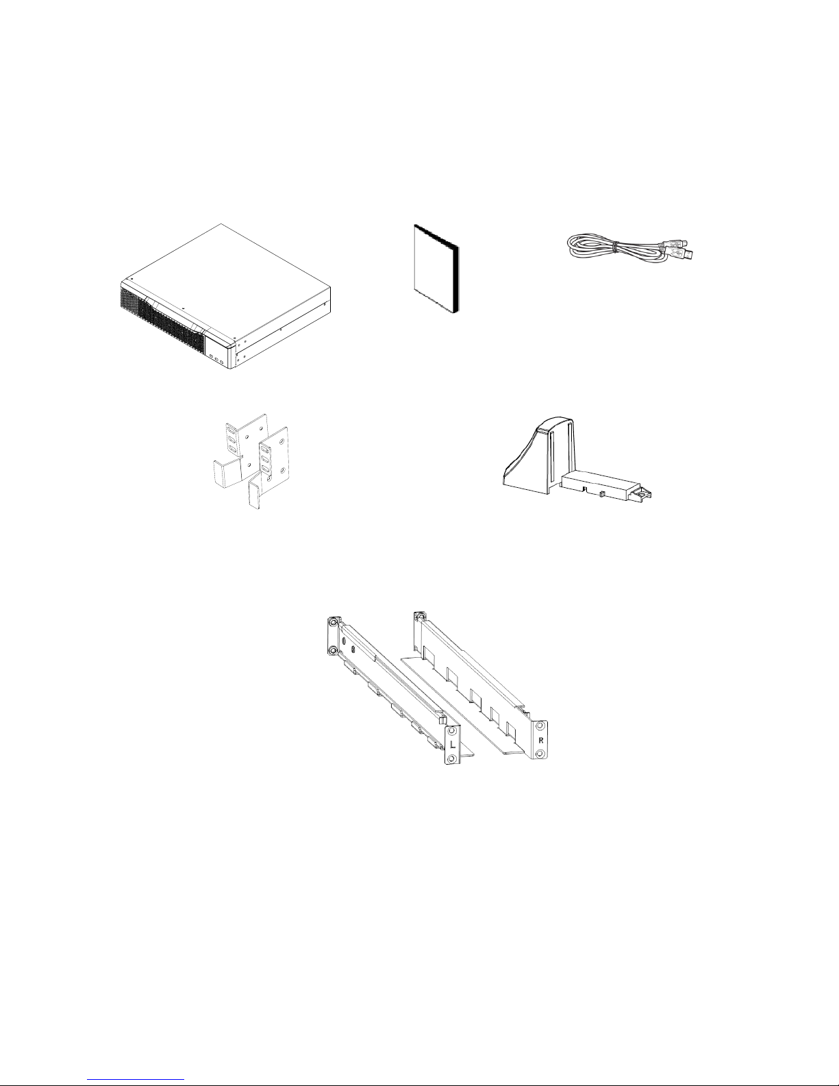
Unpacking and Inspection
Unpack your products and inspect the contents. The contents should include the following supplied
components and hardware.
1.1, 1.5, 2, or 3KVA
UPS Unit
User Manual
USB Cable
(2x) UPS Mounting Brackets and Screws
(4x) Foot
NOTE:
• Rail Slider is provided. For more information, refer to the 2U Rackmount Rail Slider instruction sheet
(I-00888.pdf).
• Before installation, inspect all supplied components and hardware to ensure nothing was damaged
during transportation. If you notice any damaged or missing parts, do not turn on the unit and notify
the carrier and utilize the support reference number provided on your unit. Please keep the original
package in a safe place for future use.
Page 10

10
Rear Panel
1.1K and 1.5K Models
2K Models
3K Models
Label Descriptions:
1. Programmable Outlets: Connect to non-critical loads.
2. Output Receptacles: Connect to critical loads.
3. AC Input
4. Network/Fax/Modem Surge Protection
5. EPO (Emergency Power Off) Function Connector
6. USB Communication Port
7. RS-232 Communication Port
8. SNMP Intelligent Slot
9. External Battery Connector
Page 11

11
Operating Principle
The operating principle of the UPS is shown as follows:
The UPS is composed of a mains input, EMI/RFI filters, inverter, battery charger, DC-to-DC converter, battery,
AVR TX, and UPS output.
Installing The UPS
For safety considerations, the UPS is ships from the factory without the battery wires connected. Before
installing the UPS, please use the following steps to first re-connect the battery wires.
Step 1: Remove the front panel. Step 2: Connect the AC input
and re-connect the battery
wires.
Step 3: Put the front panel back on
the unit.
This UPS can be either placed on a surface or mounted in a 19” rack chassis.
Rackmount Installation
CAUTION: Do not use the mounting brackets to lift the unit. Use the mounting brackets only for
securing the unit to the rack.
ATTENTION: N'utilisez pas les supports de montage pour soulever l'appareil. Utilisez les supports de
montage uniquement pour fixer l'unité au rack.
NOTE: Rail Slider is provided. For more information, refer to the 2U Rackmount Rail Slider instruction sheet
(I-00888.pdf).
Page 12

12
Use the following steps to mount your UPS system into a 19” rack.
Step 1
Step 2
Tower Installation
Step 1
Step 2
Step 3
NOTE: When using feet for tower installations of the UPS or battery pack, ensure a 2.76” (70mm) distance
from the edge of the unit to the feet as follows.
2.76”
(70mm)
2.76”
(70mm)
M4 Screw
Tower Stand
Page 13

13
Setting Up the UPS
Before installing the UPS, please read the following to select the proper location.
1. The UPS should be placed on a flat, clean surface. Place it in an area away from vibration, dust, humidity,
high temperature, flammable liquids, gases, corrosive, and conductive contaminants. Install the UPS
indoors in a clean environment, where it is away from windows and doors. Maintain a minimum
clearance of 3.94 in. (100mm) on the bottom of the UPS to avoid dust and high temperatures.
2. Maintain an ambient temperature range of 32ºF (0ºC) to 113ºF (45ºC) for optimal UPS operation. For
every 41ºF (5ºC) above 113ºF (45ºC), the UPS will derate 12% of nominal capacity at full load. The
highest working temperature requirement for operation is 122ºF (50ºC).
3. It is required to maintain a maximum altitude of 1093.61yd. (1000m) to keep the UPS within normal
operation at full load. If used in high altitudes, please reduce the connected load. Altitude derating
power with connected loads for UPS normal operation is listed as follows:
Altitude (Feet and Meters) Derating Factor
3280.84 1000 1.0
4921.26 1500 0.95
6561.68 2000 0.91
8202.1 2500 0.86
9842.52 3000 0.82
11482.94 3500 0.78
13123.36 4000 0.74
14763.78 4500 0.7
16404.2 5000 0.67
NOTE: Based on density of dry air = 1.225 kg/m3 at sea level, + 59˚F (15˚C).
4. UPS Placement
Your UPS is equipped with a fan for cooling. Therefore, place the UPS in a well-ventilated area. It’s
required to maintain minimum clearance of 4” (100mm) in the front of the UPS, and 12” (300mm) at the
back and two sides of the UPS, for heat dissipation and easy-maintenance.
UPS Input Connection
CAUTION: Plug the UPS into a two-pole, three-wire, grounded receptacle only. Avoid using
extension cords.
ATTENTION: Branchez l'onduleur dans une prise bipolaire, trois fils et mise à la terre uniquement.
Évitez d'utiliser des rallonges.
• The power cable is attached to the UPS. The input plug is a NEMA 5-15P for 1.1K and 1.5K models,
NEMA 5-20P for 2K model and NEMA 5-30P for 3K model.
NOTE: Check if the site wiring fault indicator lights up on the LCD panel. It will be illuminated when the UPS
is plugged into an improperly wired utility power outlet. For more information, see “Troubleshooting” on
page 26. Please also check if there is a circuit breaker against overcurrent and short circuit between the
mains and AC input of the UPS for safe operation. The recommended protection values are as follows:
• 15A for the 1.1K and 1.5K models
• 20A for 2K model
• 30A for 3K model
UPS Output Connections
There two kinds of outputs: programmable outlets and general outlets. Please connect non-critical devices
to the programmable outlets and critical devices to the general outlets. During a power failure, you may
extend the backup time to critical devices by setting a shorter backup time for non-critical devices.
Page 14

14
Communication Connection
Communication Ports:
USB Port RS-232 Port Intelligent Slot
To allow for unattended UPS shut down, start, and status monitoring, connect one end of the
communication cable to the USB/RS-232 port and the other end to the communication port on your PC. With
the monitoring software installed, you can schedule your UPS to shut down or start and monitor your UPS
status from your PC.
The UPS is equipped with an intelligent slot for attaching either an SNMP or an AS400 card. When installing
either card in the UPS, it will provide advanced communication and monitoring options.
Making Network Connections
Network, Phone, or Fax Surge Ports
Connect a single modem, phone, or fax line into the surge-protected “IN” outlet on the back panel of the
UPS unit. Connect from the “OUT” outlet to your equipment with another modem, phone, or fax line cable.
Disabling and Enabling the EPO Function
The UPS is equipped with an EPO (emergency power off) function. By default, the UPS is delivered from the
factory with a metal plate connecting Pin 1 and Pin2, which disables the EPO function. To activate the EPO
function, loosen the two screws and remove metal plate from the EPO port.
NOTE: The EPO function’s logic is set up via LCD settings. For more information, see Program 16 in “UPS
Settings,” on page 22.
Optional Expandable Battery Connection
Connect one end of the external battery cable into your UPS and the other end into the battery box. Use the
following illustration to connect your expandable battery.
CAUTION: External battery connections must only be performed by qualified service technicians.
ATTENTION: Les connexions de batterie externes doivent uniquement être effectuées par des
techniciens de maintenance qualifiés.
NOTE: For more information, refer to the Expandable Battery Box User Manual (I-00890.pdf).
Turning on the UPS
Press the ON/Mute button on the front panel for two seconds to power on your UPS.
NOTE: The battery charges fully during the first five hours of normal operation. Do not expect full battery
operation capability during this initial charge period.
UPS
Battery Box
Page 15

15
Installing the UPS Monitoring Software
For optimal computer system protection, install the UPS monitoring software to fully configure your UPS
shutdown procedure. Then, use the following steps to install the UPS monitoring software.
1. Download the UPS monitoring software from www.legrand.us/upsdownloads
and then follow the
on-screen instructions.
2. When your computer restarts, the monitoring software will appear as an orange plug icon located in the
system tray, near the clock.
Battery Replacement
NOTE: This UPS is equipped with internal batteries and only service person can replace the batteries.
CAUTION: Consider all warnings, cautions, and notes before replacing batteries.
ATTENTION: Tenez compte de tous les avertissements, mises en garde et remarques avant de
remplacer les piles.
NOTE: After disconnecting the ba ttery, your connected equipment is not protected from power outages.
Step 1: Remove the front panel. Step 2: Disconnect the battery
wires.
Step 3: Pull out the battery box by
removing the two screws on the front
panel.
Step 4: Remove the top cover of
the battery box and replace the
batteries inside.
Step 5: After replacing the
batteries, put the battery box
back in the original location and
replace the two screws.
Step 6: Re-connect the battery
wires.
Step 7: Put the front panel
back on the unit.
Page 16

16
Replacement Battery Assembly
NOTE: Assemble the battery kit first before installing it inside of your UPS. Select from the following battery
kit procedures for proper assembly.
2 Cell Battery Kit
Step 1: Thoroughly remove old adhesive tape
and install new tape in the following locations.
Step 2: Connect all battery terminals as shown.
Step 3: Place the connected battery packs onto
adhesive strips on one side of the plastic shells.
Step 4: Cover the other side of the plastic shell as
shown.
4 Cell Battery Kit
Step 1: Thoroughly remove old adhesive tape
and install new tape in the following locations.
Step 2: Connect all battery terminals as shown.
Step 3: Place the assembled battery packs on
adhesive strips on one side of the plastic shells.
Step 4: Cover the other side of the plastic shell as
shown.
Tap e
Tap e
Tap e
Page 17

17
6 Cell Battery Kit
Step 1: Thoroughly remove old adhesive tape
and install new tape in the following locations.
Step 2: Connect all battery terminals as shown.
Step 3: Place the assembled battery packs onto
adhesive strips on one side of the plastic shells.
Step 4: Cover the other side of the plastic shell as
shown.
Tap e
Tap e
Page 18

18
2. Operations
Button Operations
Button Function
• Turn on the UPS: Press and hold this button for at least 2 seconds to turn on
the UPS.
• Mute the alarm: While the UPS is turned on and in battery mode, press and
hold this button for at least 3 seconds to disable or enable the alarm system.
This function is overridden by warning or error alerts.
• Up key: Press this button to display the previous selection when in the UPS
settings mode.
• Switch to UPS self-test mode: While in AC mode, press and hold the ON/Mute
button for 3 seconds.
• Turn off the UPS: Press and hold this button at least 2 seconds to turn off the
UPS
• Confirm selection key: Press this button to confirm your selection while in the
UPS settings mode.
• Switch LCD message: Press this button to change the LCD message from input
voltage, input frequency, battery voltage, battery capacity, ambient
temperature, output voltage, output frequency, load current, and load percent
choices.
• Settings mode: When the UPS is off, press and hold this button for 3 seconds
to enter UPS settings mode.
• Down key: Press this button to display the next selection when in the UPS
settings mode.
+
• Exit the setting mode or return to the previous menu: When working in setting
mode, press both of these buttons simultaneously for 2 seconds to return to
the main menu. When already in the main menu, press these 2 buttons at the
same time to exit the setting mode.
Page 19

19
LCD Panel
Backup Time Information
Display Function
Indicates the backup time in pie chart.
Indicates the backup time in numbers.
H: hours, M: minute
Warning and Fault Information
Display Function
Indicates that the warning and fault occurs.
Indicates the warning and fault codes. For more information, see “Fault
Reference Codes,” on page 25 and “Warning Indicators,” on page 25.
Setting Operation
Display Function
Indicates the selected UPS setting program. For more information, see
“UPS Settings” on page 22.
Input, Battery, Temperature, Output, and Load Information
Display Function
Indicates the input voltage, input frequency, battery voltage, battery
capacity, ambient temperature, output voltage, output frequency, load
current, and load percentage.
k: kilo, W: watt, V: voltage, A: ampere, %: percent, C°: centigrade degree,
Hz: frequency
Load Information
Display Function
Indicates the load level by 0-24%, 25-49%, 50-74%, and 75-100%.
Indicates overload.
Page 20

20
UPS Status
Display Function
Indicates the UPS is connected to the mains.
Indicates that the unit is using the battery for power.
Indicates the AC to DC circuit is working.
Indicates the inverter circuit is working.
Indicates the output is working.
Indicates that programmable outlets are working.
Indicates the ECO (efficiency corrective optimizer) mode is enabled.
Indicates the UPS is working in boost mode.
Indicates the UPS is working in buck mode.
Indicates the battery charger is working.
Indicates the UPS alarm is disabled.
Battery Information
Display Function
Indicates the Battery level by 0-24%, 25-49%, 50-74%, and 75-100%.
Indicates low battery.
Audible Alarms
Reason Sound
Battery Mode Sounding every 10 seconds
Low Battery Sounding every 2 seconds
Overload Sounding every second
Fault Continuously sounding
Page 21

21
LCD Panel Index
Abbreviation Display Content Meaning
ENA
Enable
DIS
Disable
ESC
Escape
ON
ON
OK
OK
EP
EPO (Emergency Power Off)
AO
Active Open
AC
Active Close
ST 1/2/3
/ /
Input waveform sensitivity 1/2/3
AUT / AON
/
Automatic / Always on
TP
Tempera ture
CH
Charger
BF
Battery Fault
BR
Battery Replacement
EE
EEPROM Error
Operating Mode Descriptions
Operating Mode
Description
LCD Panel
ECO (Efficiency
Corrective
Optimizer) Mode
When the input voltage is within the voltage
regulated range, the UPS powers the output directly
from the mains. When the battery is fully charged in
this mode, the fan stops working to save energy.
Buck Mode
(When AC is
normal)
When the input voltage is higher than the voltage
regulation range, but lower than the high loss point,
the buck AVR (automatic voltage regulation) is
activated.
Page 22

22
Operating Mode
Description
LCD Panel
Boost Mode
(When AC is
normal)
When the input voltage is lower than the voltage
regulation range, but higher than the low loss point,
the boost AVR (automatic voltage regulation) is
activated.
Battery Mode When the input voltage is beyond the acceptable
range or when a power failure takes place and the
alarm is sounding every 10 seconds, the UPS
switches to backup power from the battery.
Standby Mode In this mode, the UPS is powered off and no outputs
are supplied power, however, the unit can still charge
the batteries.
Fault Mode When a fault occurs, the ERROR icon and the fault
code will be displayed.
UPS Settings
There are three parameters used for setting up your
UPS.
Parameter 1 is for selecting available programs for
your UPS system. See the remainder of this topic for
program details.
Parameter 2 is the setting options or values for each
program.
If another level of attenuation is available from
Parameter 2, the screen changes to show Parameter
2 and Parameter 3 as shown.
NOTE:
The following tables refer to these parameters as
Interface (Parameter 1) and Setting (Parameter 2) or
(Parameter 3), respectively.
Enter Settings mode before performing the following configurations. To enter the UPS settings mode, your
UPS needs to be OFF. With the unit off, press and hold the Select button for 5 seconds.
For more information, see “Button Operations” on page 18.
Parameter 2
Parameter 1
Parameter 3
Parameter 2
Page 23

23
01: Output Voltage Setting
Interface Setting
For 110/115/120/127 Vac models, you may choose the following output
voltage:
110: The output voltage is 110Vac
115: The output voltage is 115Vac
120: The output voltage is 120Vac (Default)
127: The output voltage is 127Vac
02: Programmable Outlets (Enable/Disable)
Interface Setting
Enable or disable programmable outlets.
ENA: The programmable outlet is enabled
DIS: The programmable outlet is disabled (Default)
03: Programmable Outlets Setting
Interface Setting
Set up backup time limits for all programmable outlets.
0-999: Set the backup time limits in minutes from 0-999 for
programmable outlets which connect to non-critical devices in battery
mode. (Default: 999)
04: Site Fault Detection (Enable/Disable)
Interface Setting
Enable or disable site fault detection.
ENA: Site fault detection enabled (Default)
DIS: Site fault detection disabled
05: Autonomy Limitation Setting
Interface Setting
Sets up backup time for general outlets when in battery mode.
0-999: setting the backup time in minutes from 0-999 for general outlets
on battery mode.
DIS: Disable the autonomy limitation and the backup time will depend on
battery capacity. (Default)
NOTE:
• When enabled, if the set time duration is less than the programmable
outlet setting, it overrides the latter.
• When setting as “0”, the backup time will be only 10 seconds.
Page 24

24
06: Battery Total Ah Setting
Interface Setting
Sets up the battery total Ah of the UPS.
7-81: Set the total capacity of the battery from 7-81 in AH.
NOTE: Be sure to set the correct total capacity of the battery, including the
external battery bank, if used.
07: EPO Logic Setting
Interface Setting
Sets up the EPO (Emergency Power Off) function control logic.
AO: Active Open (Default). When AO is selected as EPO logic, it will activate
EPO function with Pin 1 and Pin 2 in open status.
AC: Active Close. When AC is selected as EPO logic, it will activate EPO
function with Pin 1 and Pin 2 in close status.
08: Input Waveform Sensitivity Setting
Interface Setting
Sets the input waveform sensitivity when connected to a generator.
St1: Input voltage waveform detection is set to high sensitivity. (Default)
St2: Input voltage waveform detection is set to middle sensitivity.
St3: Input voltage waveform detection is set to low sensitivity. (St3 is
recommended for generator input.)
09: LCD Display Backlight Setting
Interface Setting
Sets up the working mode for the LCD display backlight.
Aon: LCD display backlight is on all the time. (Default)
Aut: LCD display backlight turns off 60 seconds after the last button press.
00: Exit Settings
Interface Setting
Exit the settings mode.
Page 25

25
Fault Reference Codes
Fault Event Fault Code Icon Fault Event Fault Code Icon
Bus start fail 01 None Inverter output short 14 None
Bus over 02 None Battery voltage too high 27 None
Bus under 03 None Battery voltage too low 28 None
Inverter soft start fail 11 None Over temperature 41 None
Inverter voltage high 12 None Overload 43
Inverter voltage Low 13 None Charger failure 45 None
Warning Indicators
Warning Icon (Flashing) Alarm
Low Battery
Sounding every 2 seconds
Overload
Sounding every second
Battery Disconnected
Sounding every 2 seconds
Overcharge
Sounding every 2 seconds
Site Wiring Fault
Sounding every 2 seconds
EPO (Emergency Power Off) Enabled
Sounding every 2 seconds
Over Temperature
Sounding every 2 seconds
Charger Failure
Sounding every 2 seconds
Battery Fault
Sounding every 2 seconds
(At this time, UPS is off to remind users of
something wrong with battery)
EEPROM Error
Sounding every 2 seconds
Battery Replacement
Sounding every 2 seconds
Page 26

26
4. Troubleshooting
If the UPS system does not operate correctly, please solve the problem by using the table below.
Issue Possible Cause Solution
No indication showing on LED or alarm
sounding that there’s power coming
into the unit.
The AC input power is not
connected well.
Check if input power cable
firmly connected to the mains.
The AC input is connected to
the UPS output.
Plug the AC input power cable
into the AC input.
The icon and the warning code
are flashing on LCD screen and
alarm is sounding every 2 seconds.
EPO (emergency power off)
function is activated.
Set the circuit in close position
to disable EPO function.
The icon and are flashing
on LCD screen and alarm is sounding
every 2 seconds.
Line and neutral conductors of
UPS input are reversed.
Rotate mains power socket by
180° and then connect to UPS
system.
The icon and are flashing
on LCD screen and alarm is sounding
every 2 seconds.
The external or internal
battery is incorrectly
connected.
Check if all batteries are
connected well.
Fault code is shown as 27 and the
alarm is continuously sounding.
Battery voltage is too high or
the charger is fault.
Contact your dealer.
Fault code is shown as 28 and the
alarm is continuously sounding.
Battery voltage is too low or
the charger is faulty.
Contact your dealer.
The icon and the icon are
flashing on LCD screen and alarm is
sounding every second.
UPS is overloaded Remove excess loads from UPS
output.
Fault code is shown as 43 and the icon
is lighting on LCD screen and
alarm is continuously sounding.
The UPS shut down
automatically because of an
overload at the UPS output.
Remove excess loads from UPS
output and restart it.
Fault code is shown as 14 and alarm is
continuously sounding.
The UPS shut down
automatically because a short
circuit occurred at the UPS
output.
Check output wiring and if
connected devices are in short
circuit status.
Fault code is shown as 01, 02, 03, 11,
12, 13 and 41 on the LCD screen and
alarm is continuously sounding.
A UPS internal fault has
occurred.
Contact your dealer
The battery backup time is shorter
than the nominal value.
The batteries are not fully
charged.
Charge the batteries for at
least 5 hours, and then check
capacity. If the problem still
persists, consult your dealer.
The batteries are defective. Contact your dealer to replace
the battery.
Fault code is shown as 45 on LCD
screen. At the same time, alarm is
continuously sounding.
The charger does not have
output and the battery voltage
is less than 10V/PC.
Contact your dealer.
Page 27

27
5. Maintenance and Storage
Maintenance
The UPS system contains no user-serviceable parts. If the battery service life (3~5 years at 77°F, 25°C
ambient temperature) has been exceeded, the batteries must be replaced. Contact technical support.
Storage
Before storing your UPS for long periods of time, charge the system for 5 hours. Store the UPS covered
and upright in a cool, dry location. While in storage, recharge the battery as follows:
Storage Temperature Recharge Frequency Charging Duration
-13°F to 104°F (-25°C to 40°C) Every 3 months 1-2 hours
104°F to 113°F (40°C to 45°C) Every 2 months 1-2 hours
Be sure to bring discharged batteries to a recycling facility or ship it to your dealer in the
replacement battery packing material.
Page 28

28
6. Specifications
NOTE: Product specifications are subject to change without notice.
Input
MODEL/CAPACITY
1100VA
990W
1500VA
1350W
2000VA
1800W
3000VA
2700W
Acceptable Voltage
Range
81-145 Vac
Frequency Range 60/50 Hz (auto sensing)
Output
MODEL/CAPACITY
1100VA
990W
1500VA
1350W
2000VA
1800W
3000VA
2700W
Voltage Regulation
(Battery Mode)
110/115/120/127 Vac ±1.5% (before battery alarm)
Frequency Range
(Battery Mode)
50 Hz or 60 Hz ± 1 Hz
Current Crest Ratio 3:1
Harmonic Distortion
2% max @ 100% linear load, 5% max @ 100% non-linear load
(before low battery alarm)
Transfer Time Typical 2-6 ms, 10ms max.
Waveform
(Battery Mode)
Pure Sine Wave
Efficiency
MODEL/CAPACITY
1100VA
990W
1500VA
1350W
2000VA
1800W
3000VA
2700W
AC Mode 95%
Buck & Boost Mode 93%
Battery Mode 88% 90% 90%
Battery
MODEL/CAPACITY
1100VA
990W
1500VA
1350W
2000VA
1800W
3000VA
2700W
Battery Type & Number 12 V/9 Ahx2 12 V/7 Ahx4 12 V/9 Ahx4 12 V/9 Ahx6
Charging Voltage 27.4 VDC ± 1% 54.8 VDC ± 1% 82.1 VDC ± 1%
Recharge Time 4 hours recover to 90% capacity
Charging Current 1.5A
Protection
MODEL/CAPACITY
1100VA
990W
1500VA
1350W
2000VA
1800W
3000VA
2700W
Full Protection Overload, short, discharge, and overcharge protection
Page 29

29
Alarm
MODEL/CAPACITY
1100VA
990W
1500VA
1350W
2000VA
1800W
3000VA
2700W
Battery Mode Sounding every 10 seconds
Low Battery Sounding every 2 seconds
Overload Sounding every second
Battery Replacement
Alarm
Sounding every 2 seconds
Fault Continuously sounding
Physical
MODEL/CAPACITY
1100VA
990W
1500VA
1350W
2000VA
1800W
3000VA
2700W
Dimension, D x W x H
(inches)
16.1 x 17.2 x 3.4 20.0 x 17.2 x 3.4 24.8 x 17.2 x 3.4
Dimension, D x W x H
(mm)
410 x 438 x 88 510 x 438 x 88 630 x 438 x 88
Net Weight (lbs) 29.5 42.9 47.3 64.5
Net Weight (kgs) 13.4 19.5 21.5 29.3
Environment
MODEL/CAPACITY
1100VA
990W
1500VA
1350W
2000VA
1800W
3000VA
2700W
Operating Humidity 0-90 % RH @ 32 – 104°F or 0 – 40°C (non-condensing)
Acoustic Noise Level Less than 45dBA @ 1 Meter
Management
MODEL/CAPACITY
1100VA
990W
1500VA
1350W
2000VA
1800W
3000VA
2700W
Smart RS-232/USB Supports Windows® 2000/2003/XP/Vista/2008, 7/8, Linux, Unix, and MAC
Optional SNMP Power management from SNMP manager and web browser
Page 30

30
Expandable Battery Box Specification
M
ODEL/CAPACITY 18Ah24V 18Ah48V 18Ah72V
Used with UPS Models
1.1K 1.5~2K 3K
Battery Type
12V 9Ah 12V 9Ah 12V 9Ah
Battery Numbers
4 8 12
Dimension, D
x W x H
(
inches)
16.1 x 17.2 x 3.5 20.1 x 17.2 x 3.5 24.8 x 17.2 x 3.5
Dimension, D
x W x H
(mm)
410 x 438 x 88 510 x 438 x 88 630 x 438 x 88
Net Weight (
lbs) 37.69 63.93 90.83
Net Weight (kg
s) 17.1 29 41.2
NOTE: Battery pack should be used with corresponding UPS.
 Loading...