

Page 1
301 Fulling Mill Road, Suite G
Middletown, PA 17057
Phone (800) 321-2343 / Fax (717) 702-2546
www.onqlegrand.com
1. Introduction
The On-Q/Legrand 1x6 Basic Telecom (P/N 1267062-01) and 6
Port Telecom Expansion Module (P/N 1267058-01) provide a
structured method for distributing telephone service through-out
a residence. The modules occupy three (3) vertical inches and
span half the width of an On-Q Service Center Enclosure.
2. Description
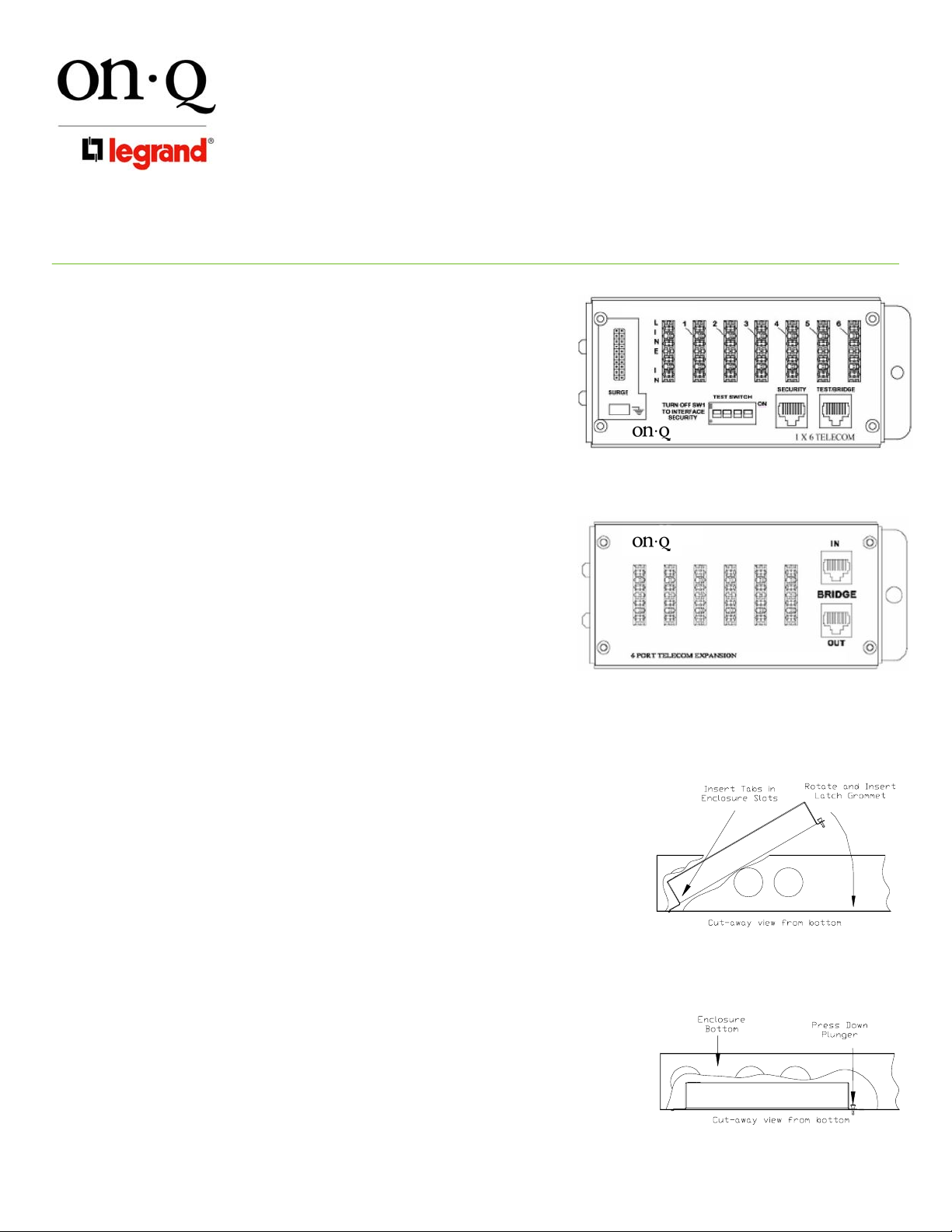
The 1x6 Telecom Module (see Figure 1) has an eight position
110 punch-down connector for connecting the incoming four line
service, a two row 20 position posted connector and spade
terminal for optional surge protection (On-Q P/N 363487-01).
There is a vertical RJ45 jack for test for local handset attachment
and an additional vertical RJ45 jack for the RJ31X security
interface. Six 8 position 110 punch-down connectors for
connecting the outlets to the system are available. The module
also features a 4-position switch to allow separation of the
incoming lines from the outlets for testing purposes. The switch
is also used to activate the security option. The Telecom
Expansion Module (also see Figure 1) has two RJ45 vertical
telephone jacks for bridging connections and six 8 position, 110
punch-down connectors for outlet distribution.
3. Installation
A. Mounting in Enclosure - See Figure 2
1) Align tabs on the module with slots on rail of enclosure.
2) Insert tabs angling module away from the back of the enclosure.
3) Rotate the module and insert fasteners on module into
corresponding holes on rail of enclosure. (Plunger must be in a
pulled position for fastener to engage hole)
4) Push plunger in to lock module in place. Pull on module to
ensure module is locked properly in place.
B. Incoming Service Cable Installation (1x6 Telecom)
1) Identify incoming service cable and route to “Line In” 110 punchdown block. In routing cable, allow slack or bundling to the side
and avoiding other cable terminations. Trim cable about 2
inches beyond connector.
2) Strip off approximately 4 inches of the outer jacket using On-Q
Strip Tool (P/N 363292-01 or equivalent).
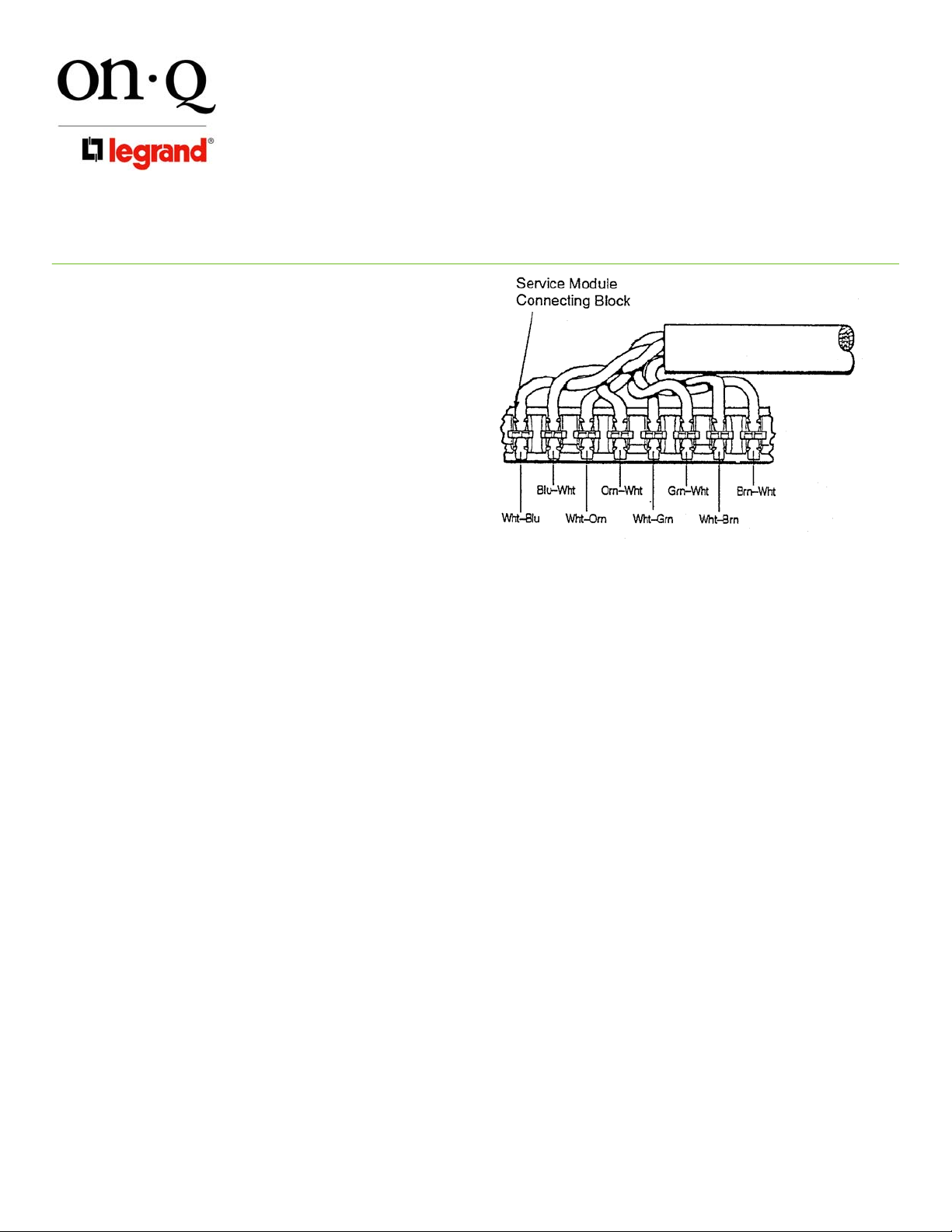
3) Position pairs over color-coded slots on the connector (see
Figure 3).
NOTE: Do NOT untwist pairs.
INSTRUCTION / INSTALLATION SHEET
Telecom Modules
IS-0058 Rev. E
Figure 1
Figure 2
©Copyright 2007 by On-Q/Legrand All Rights Reserved. Page 1 of 3
Page 2
301 Fulling Mill Road, Suite G
Middletown, PA 17057
Phone (800) 321-2343 / Fax (717) 702-2546
www.onqlegrand.com
INSTRUCTION / INSTALLATION SHEET
Telecom Modules
IS-0058 Rev. E
NOTE: White wires may not have color trace
stripe. Keep white wire paired with
appropriate colored wire based on twist.
4) Without untwisting cable, position the wires
in individual slots (see Figure 3).
5) Punch-down and trim wires using On-Q
Punch-Down Tool (P/N 363293-01 or
equivalent).
6) Remove excess wire & tug slightly to
ensure wire is securely installed in
connector.
C. Incoming Service Cable Installation
(Telecom Expansion)
1) Connect one end of the supplied CAT5E
jumper cable to the RJ45 jack labeled
“Test/Bridge” on the 1x6 Telecom Module
and connect the other end to the RJ45 jack
labeled “Bridge In” on the Telecom Expansion Module.
2) To install additional Telecom Expansion Modules, connect one end of the supplied CAT5E jumper to the
RJ45 jack labeled “Bridge Out” on the first Telecom Expansion Module and connect the other end to the
“Bridge In” RJ45 on the second Telecom Expansion Module.
3) If connecting to a 1x11 Basic Telecom Module (P/N 363484-01), connect the CAT5E jumper between the
RJ45’s labeled “Test Bridge” and “Bridge In”.
D. Outlet Cable Termination
1) Identify outlet cable and route to a numbered 110 punch-down block. In routing cable, allow slack for
bundling to the side and avoiding other cable terminations. Trim cable about 2 inches beyond connector.
2) Strip off approximately 4 inches of the outer jacket using On-Q Strip Tool (P/N 363292-01 or equivalent).
3) Position pairs over color-coded slots on the connector (see Figure 3).
4) Without untwisting cable, position the wires in individual slots (see Figure 3).
5) Punch-down and trim wires using On-Q Punch-Down Tool (P/N 363293-01 or equivalent).
6) Remove excess wire and tug slightly on cable to ensure wire is securely installed in connector.
7) Record room name/number to connector number on a wire layout list and place list in enclosure.
8) Repeat until all outlets are connected.
NOTE: To complete proper cross connect, install a CAT5E jumper (P/N 363201-27).
E. Securing Cables
After all cables are connected to the module, the cables should be bundled and grouped to allow ease of
maintenance. On-Q Wire Management Straps (P/N 363491-01), may be used to bundle cable.
Figure 3
4. Testing
A. To test the outlet wiring from the Telecom Modules to the wall outlets, turn all switches on “Test Switch” to
“OFF”. Insert line tester into the RJ45 jack labeled “Test/Bridge”. Perform check at each wall outlet. All
outlets, including those on the Telecom Expansion Module, will be testable.
©Copyright 2007 by On-Q/Legrand All Rights Reserved. Page 2 of 3
Page 3

301 Fulling Mill Road, Suite G
Middletown, PA 17057
Phone (800) 321-2343 / Fax (717) 702-2546
www.onqlegrand.com
B. To reset module to normal operation, ensure all switches are set to the “ON” position.
5. Other Applications
A. Security Interface
1) To enable line seizure and dial out capability to most security systems, connect the RJ31X cable
(supplied w/security system), to the RJ45 “Security” jack on the module. Turn Test Switch #1 to the OFF
position to activate the RJ31X. Connect the other end to the security systems as outlined in the security
system installatio n instru ction s.
2) To disable security, remove plug from “security” jack and set line 1 to “ON”.
NOTE: Line 1 Blue Pair is sent to the RJ-31X jack.
B. Surge Protection
See instructions supplied with On-Q Surge Suppression Unit (P/N 363487-01).
INSTRUCTION / INSTALLATION SHEET
Telecom Modules
IS-0058 Rev. E
©Copyright 2007 by On-Q/Legrand All Rights Reserved. Page 3 of 3
 Loading...