

Page 1

009-10602-A
June 2003
Legra Radio LR11b
Installation Guide
inary
elim
Pr
Legra Systems Inc. Proprietary and Confidential
Page 2

©2003 Legra Systems
This equipment has been tested and found to comply with the limits for a Class B digital device, pursuant to Part 15 of the FCC Rules. These limits are
designed to provide reasonable protection against harmful interference in a residential installation. This equipment generates, uses and can radiate radio
frequency energy and, if not installed and used in accordance with instructions, may cause harmful interference to radio communications. However,
there is no guarantee that the interference will not occur in a particular installation. If this equipment does cause harmful interference to radio or television
reception, which can be determined by turning the equipment off and on, the user is encouraged to try to correct the interference by one or more of the
following measures:
• Reorient the receiving antenna
• Increase the separation between the equipment and receiver
• Connect the equipment into an outlet on a circuit different from that to which the receiver is connected
• Consult the dealer or an experienced radio/TV technician for help
FCC Caution: To assure continued compliance, (example - use only shielded interface cables when connecting to computer or peripheral devices). Any
changes or modifications not expressly approved by the party responsible for compliance could void the user’s authority to operate this equipment. This
device complies with Part 15 of the FCC Rules. Operation is subject to the following two conditions: (1) This device may not cause harmful interference,
and (2) this device must accept any interference received, including interference that may cause undesired operation.
This product includes cryptographic software written by Eric Young ([email protected]). THIS SOFTWARE IS PROVIDED BY ERIC YOUNG “AS IS”
AND ANY EXPRESS OR IMPLIED WARRANTIES, INCLUDING, BUT NOT LIMITED TO, THE IMPLIED WARRANTIES OF MERCHANTABILITY AND
FITNESS FOR A PARTICULAR PURPOSE ARE DISCLAIMED. IN NO EVENT SHALL THE AUTHOR OR CONTRIBUTORS BE LIABLE FOR ANY
DIRECT, INDIRECT, INCIDENTAL, SPECIAL, EXEMPLARY, OR CONSEQUENTIAL DAMAGES (INCLUDING, BUT NOT LIMITED TO,
PROCUREMENT OF SUBSTITUTE GOODS OR SERVICES; LOSS OF USE, DATA, OR PROFITS; OR BUSINESS INTERRUPTION) HOWEVER
CAUSED AND ON ANY THEORY OF LIABILITY, WHETHER IN CONTRACT, STRICT LIABILITY, OR TORT (INCLUDING NEGLIGENCE OR
OTHERWISE) ARISING IN ANY WAY OUT OF THE USE OF THIS SOFTWARE, EVEN IF ADVISED OF THE POSSIBILITY OF SUCH DAMAGE.
All other trademarks mentioned in this document are the property of their respective owners.
inary
elim
Pr
Legra Systems Inc. Proprietary and Confidential
Page 3

Contents
Contents................................................................................... iii
Figures ...................................................................................... v
Tables...................................................................................... vii
Introduction ............................................................................. ix
Intended Audience ................................................................. ix
Objective ................................................................................. ix
About this Guide ..................................................................... x
Documentation Conventions ................................................. x
Related Documents ................................................................ xi
Documentation Feedback .................................................... xii
Technical Assistance ............................................................ xii
Chapter 1 Overview
Key Features ............................................................................. 2
Power over Ethernet (PoE) Compatibility ................................................ 3
Radio Characteristics ............................................................................... 4
MAC Addresses .......................................................................................4
LED Indicators .........................................................................................4
Additional Tools/Items ............................................................... 7
Unpacking the Legra Radio ....................................................... 8
Package Contents ................................................................................... 8
Setup Overview ....................................................................... 10
LR11b Radio Configuration ...................................................................11
Legra Systems Inc. Proprietary and Confidential
iii
Page 4

Legra Manager LM6000 NMS User Guide 009-30422-A
Chapter 2 Installation
Safety Information ................................................................... 14
FCC Safety Compliance Statement ....................................................... 14
General Safety Guidelines ..................................................................... 14
Warnings ................................................................................................ 15
Installation Guidelines ............................................................. 16
Chapter 3 Mounting Instructions
Overview ................................................................................. 18
Installing the Mounting Bracket .............................................................. 18
Attaching the Legra Radio to the Mounting Bracket .............................. 19
Removing the Legra Radio from the Mounting Bracket ......................... 20
Imprinting a Legra Radio .......................................................................20
Connecting Power to the Legra Radio ................................................... 21
Power over Ethernet (PoE) ............................................................. 21
Inline Power Injector ........................................................................ 22
Power Brick ..................................................................................... 22
Appendix A Specifications
iv
Legra Systems Inc. Proprietary and Confidential
Page 5

009-10602-A Legra Radio Installation Guide
Figures
Figure 1-1 Legra Radio LR11b ............................................. 2
Figure 1-2 Legra Radio Aft Connectors ................................ 3
Figure 1-3 Legra Radio LEDs ............................................... 5
Figure 3-1 Legra Radio LR11b Mounting Bracket .............. 18
Figure 3-2 Legra Radio Power Brick (Sold Separately) ...... 22
Legra Systems Inc. Proprietary and Confidential
v
Page 6

Legra Radio Installation Guide 009-10602-A
vi
Legra Systems Inc. Proprietary and Confidential
Page 7

009-10602-A Legra Radio Installation Guide
Tables
Table 1-1 LED Status Descriptions ...................................... 5
Table 1-2 Legra Radio LR11b Package Contents ............... 8
Table A-1 Performance Specifications ..............................A-1
Table A-2 General Specifications ......................................A-1
Table A-3 Compliances .....................................................A-2
Legra Systems Inc. Proprietary and Confidential
vii
Page 8

Legra Radio Installation Guide 009-10602-A
viii
Legra Systems Inc. Proprietary and Confidential
Page 9

Intended Audience
The Legra Radio LR11b Installation Guide is intended for network or
computer technicians responsible for installing the LR11b. The
following assumptions are made:
• The user will read this guide prior to installation.
• The user is familiar with concepts and terminology of wireless local
area networking (WLAN).
Introduction
Objective
The Legra Radio LR11b Installation Guide describes the Legra Radio
hardware features, physical and performance characteristics, and
explains how to install the Legra Radio.
For information about configuring the LR11b and associated
components, see “Related Documents” on page xi.
Legra Systems Inc. Proprietary and Confidential
ix
Page 10

Legra Radio Installation Guide 009-10602-A
About this Guide
The Legra Radio LR11b Installation Guide is organized into the
following chapters:
Chapter Description
Chapter 1, Overview Contains an overview of the Legra Radio physical and
Chapter 2, Installation Contains the warnings, installation instructions, and
Chapter 3, Mounting Instructions Contains instructions for installing the LR11b on the
Appendix A, Specifications Lists the physical and environmental specifications of the
functional characteristics, including the LEDs and supported
standards.
unpacking information for installing the LR11b.
contained mounting brackets.
LR11b and regulatory approvals.
Documentation Conventions
This document uses the following conventions for Warnings, Cautions,
and Notes:
WARNING A Warning means danger. The reader is in a situation that could result
in bodily injury. Follow standard practices for preventing accidents.
CAUTION
x
A Caution means that the reader should take care to avoid damage to
the equipment.
Legra Systems Inc. Proprietary and Confidential
Page 11

009-10602-A Legra Radio Installation Guide
NOTE A note means that the reader should take note. Notes contain helpful
suggestions or references to related documents.
Related Documents
The following documents provide additional information about the
LR11b and associated components:
Number Title
009-20418-A
009-60422-A
009-20505-B
009-60610-A
009-10610-A
Legra Switch LS2012 User Guide
Legra Manager LM6000 User Guide
Legra Switch LS2012 Installation Guide
Legra Manager LM6000 Installation Guide
Legra Radio LR11b Quick Start Guide
You can download the above documents in the Support section of the
the Legra Systems Inc. web site:
http://www.legra.com/
Legra Systems Inc. Proprietary and Confidential
xi
Page 12

Legra Radio Installation Guide 009-10602-A
Documentation Feedback
You can submit feedback about Legra documentation at the following
email address:
Technical Assistance
You can reach Legra technical support at the Legra web site:
http://www.legra.com
xii
Legra Systems Inc. Proprietary and Confidential
Page 13

This chapter describes:
• Key Features
• Additional Tools/Items
• Unpacking the Legra Radio
• Setup Overview
1
Overview
Legra Systems Inc. Proprietary and Confidential
1
Page 14
Legra Radio Installation Guide 009-10602-A
Key Features
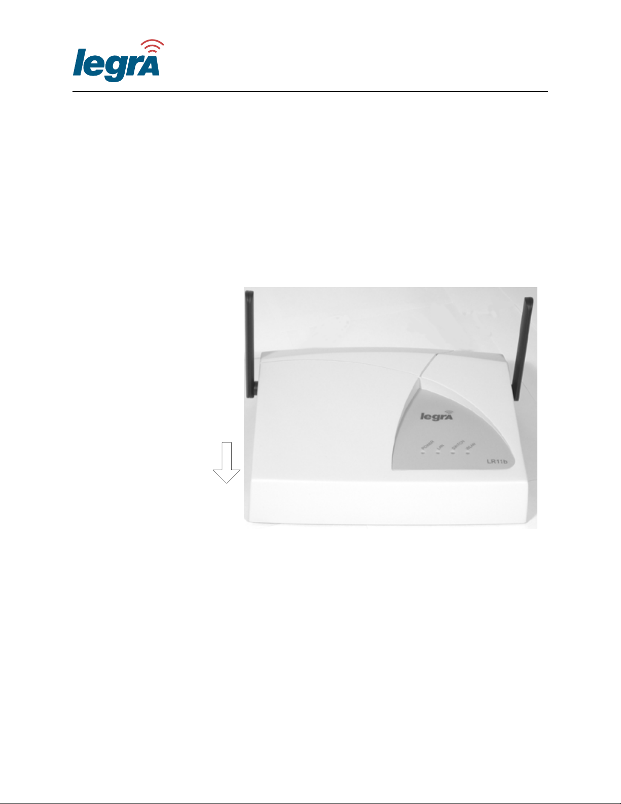
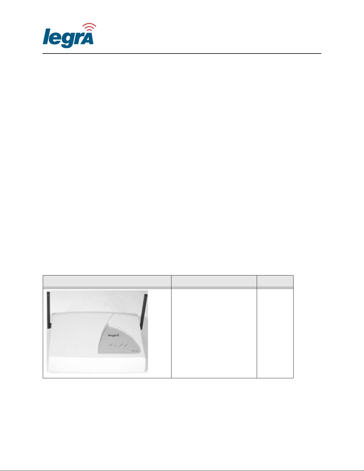
The Legra Radio LR11b (Figure 1-1) access point provides wireless
high-speed data communications between a switch and end user
stations equipped with 802.11b wireless adapters. You can connect a
Legra Radio directly to a Legra Switch with a category 5 Ethernet
cable, or third-party switch.
Forward
Figure 1-1 Legra Radio LR11b
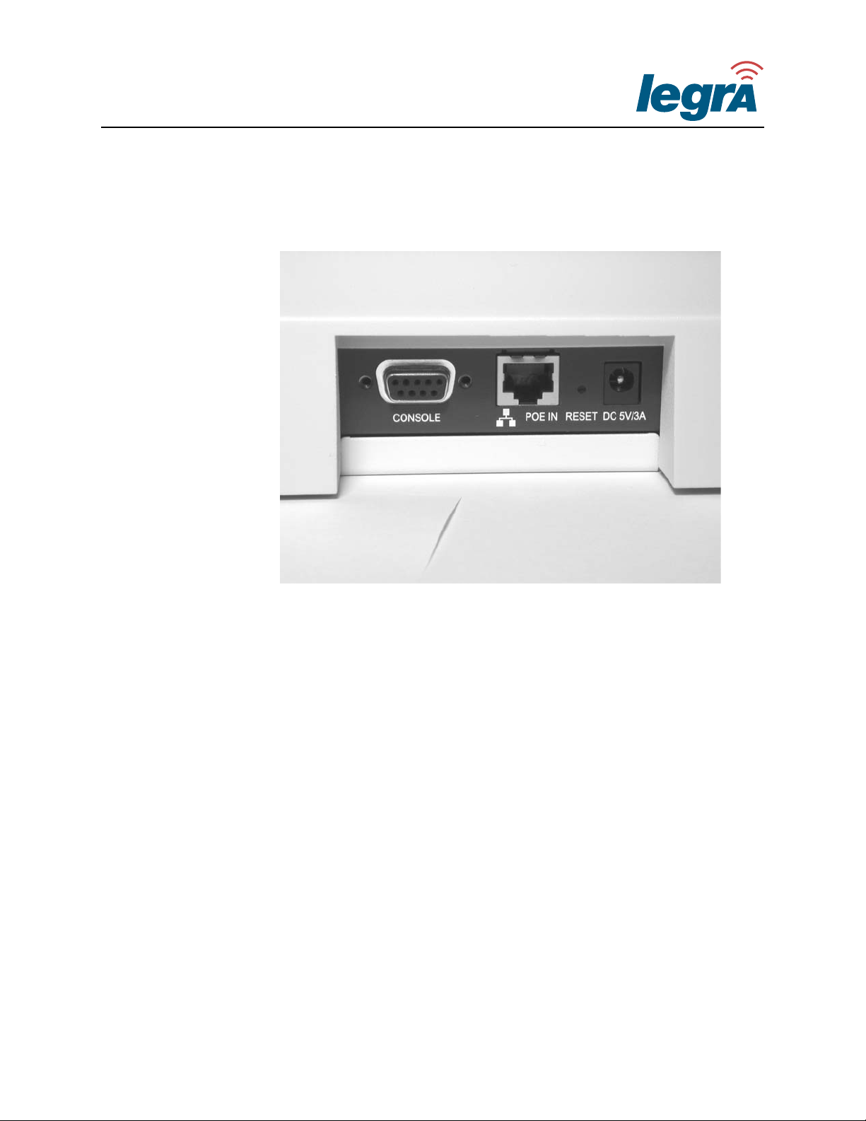
The Legra Radio can be powered by Power over Ethernet (PoE)
provided through the RJ-45 Ethernet connector (Figure 1-2). When
2 Key Features
Legra Systems Inc. Proprietary and Confidential
Page 15
009-10602-A Legra Radio Installation Guide
connected to a Legra Switch, the Legra Radio downloads software
from the Legra Switch.
Figure 1-2 Legra Radio Aft Connectors
You can also connect the Legra Radio to a third-party vendor’s switch
and manage the Legra Radio from a Legra Switch through your
network. During the Radio’s initial configuration, you must imprint the
Legra Switch’s DNS information on the Legra Radio. For more
information, see “Imprinting a Legra Radio” on page 20.
If your third party switch does not support PoE, you can use an inline
power injector to power the Legra Radio, or connect a Legra power
brick to the 5V DC Power Socket.
Power over Ethernet (PoE) Compatibility
The Legra Radio is Power over Ethernet ready in accordance with
IEEE 802.3af. The Legra Radio has a RJ-45 10/100 Ethernet connector
Legra Systems Inc. Proprietary and Confidential
Overview 3
Page 16

Legra Radio Installation Guide 009-10602-A
(Figure 1-2). Using a category 5 cable, you can connect the Legra
Radio directly to 10/100 Ethernet port on the Legra Switch LS2012, or
a third party switch that supports PoE.
If your third party switch does not support PoE, you can use an inline
power injector or a Legra power brick (sold separately) to provide
power to the Legra Radio.
Radio Characteristics
The Legra Radio uses a radio modulation technique known as
Orthogonal Frequency Division Multiplexing (OFDM), and a shared
collision domain (CSMA/CA). Data is transmitted over a half-duplex
radio channel operating at up to 11 Megabits per second (Mbps), and
with a maximum operating range up to 500 meters (1640 feet).
MAC Addresses
LED Indicators
The Legra Radio is preconfigured with two Media Access Control
(MAC) addresses: one for the ethernet network connection, and one for
the wireless connection with an end user station. You can view the
MAC addresses on the labels located on the bottom of the Legra Radio.
The ethernet MAC Address also appears in the LM6000 Network
Management System (NMS) and Legra Switch LS2012 User interface
when you configure your network.
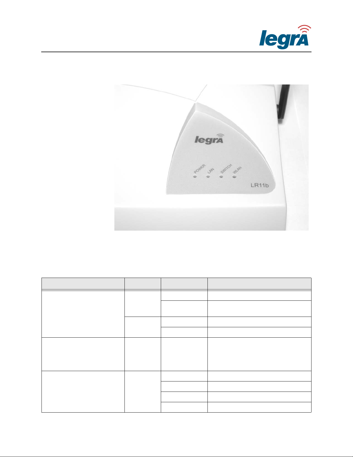
The Legra Radio includes four status LED indicators, as described in
Figure 1-3 and Table 1-1.
4 Key Features
Legra Systems Inc. Proprietary and Confidential
Page 17
009-10602-A Legra Radio Installation Guide
Figure 1-3 Legra Radio LEDs
Table 1-1 LED Status Descriptions
LED Color Status Description
Solid On Indicates that power is being supplied.
Power
LAN
Switch
Green
Flashing
Slow Flashing Imprinting information incomplete
Amber
Fast Flashing Initialization failure
Green Flashing
On Indicates LS2012 connection.
Off No LS2012 connection.
Green
Slow Flashing Searching for LS2012 connection.
Fast Flashing Software upgrade in progress.
Indicates imprinting of LS2012
parameters in progress
Indicates that the Legra Radio is
transmitting or receiving data on a 10/
100 Mbps Ethernet LAN from the
switch. Flashing rate is proportional to
network activity.
Legra Systems Inc. Proprietary and Confidential
Overview 5
Page 18
Legra Radio Installation Guide 009-10602-A
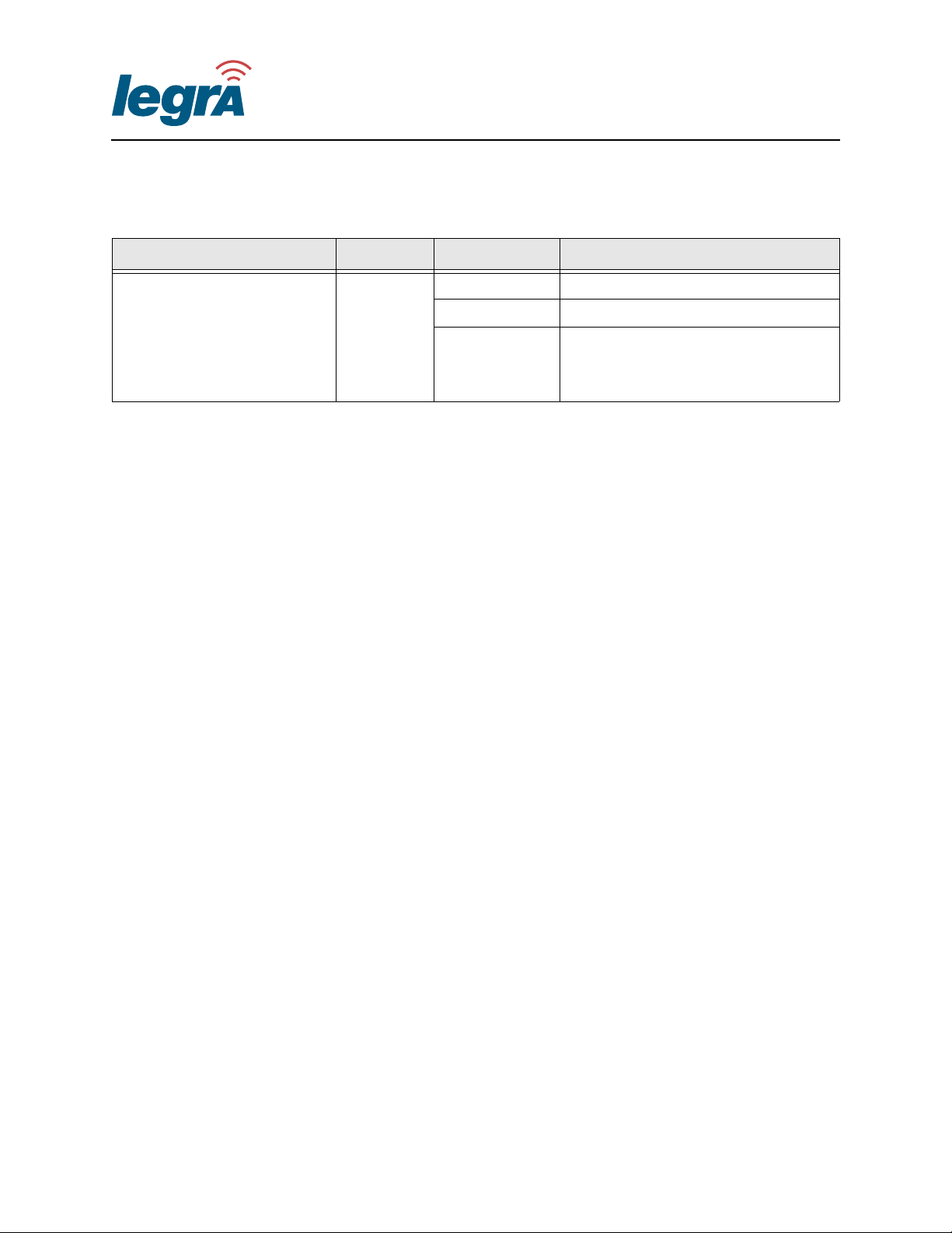
Table 1-1 LED Status Descriptions (Continued)
LED Color Status Description
On Indicates a valid 802.11b wireless link.
Off No WLAN Activity
WLAN
Green
Flashing
Indicates that the Legra Radio is
transmitting or receiving data through
wireless links. Flashing rate is
proportional to network activity.
6 Key Features
Legra Systems Inc. Proprietary and Confidential
Page 19

009-10602-A Legra Radio Installation Guide
Additional Tools/Items
You will need the following to install and connect your Legra Radio:
• Category 5 Ethernet cable (100 meters maximum) to connect the
radio to a Legra or third party switch.
• 3/16-inch drill for installing wall anchors.
• Power Drill for installing wall anchors.
• Phillips head screwdriver
Legra Systems Inc. Proprietary and Confidential
Overview 7
Page 20
Legra Radio Installation Guide 009-10602-A
Unpacking the Legra Radio
This section describes the contents of the Legra Radio LR11b
packaging.
To unpack the Legra Radio
1 Open the box and carefully remove the contents. Save the packing
materials.
2 Ensure that all items listed in “Package Contents” on page 8 are
included in the shipment. Check each item for damage. If any item
is damaged or missing, notify your Legra Systems representative.
Package Contents
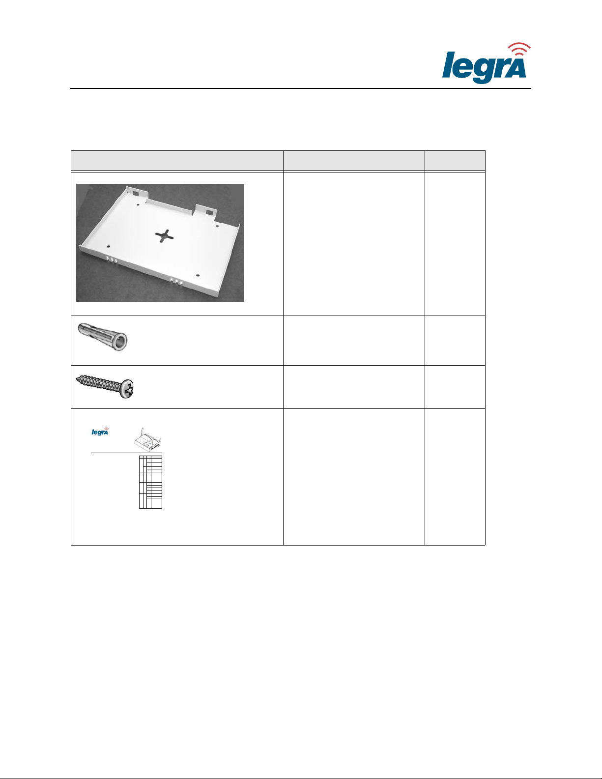
The Legra Radio package includes items shown in Table 1-2.
Table 1-2 Legra Radio LR11b Package Contents
Picture Item Qty
Legra Radio LR11b 1
8 Unpacking the Legra Radio
Legra Systems Inc. Proprietary and Confidential
Page 21
009-10602-A Legra Radio Installation Guide
009-10610-01 ©2003 Legra Systems Inc.
Legra Systems Inc. Proprietary and Confidential
The Legra Radio LR11b access point
provides wireless high-speed data
communications between a switch,
such as the Legra Switch LS2012, and
end user stations equipped with
802.11b wireless adapters. You can
connect a Legra Radio to a Legra
Switch or third party switch with a
category 5 Ethernet cable.
The Legra Radio is Power over
Ethernet (PoE) ready in accordance
with IEEE 802.3af. If your third party
switch does not support PoE, you can
use an inline power injector or a Legra
power brick (sold separately) to power
the Legra Radio.
Package Contents
Getting Documentation
Before installing and configuring your
Legra Radio LR11b, download and
read the latest versions of Legra
documents at the Legra Support web
site:
http://www.legra.com
Support Contact
Information
For technical support, visit the Support
section of the Legra website.
http://www.legra.com
Related Documents
Download and read the following
documents before installing and
configuring your Legra Radio LR11b:
Additional Tools/Items
You may need the following to install
your Legra Radio (items available
separately):
• Category 5 Ethernet cable
• Phillips head screwdriver
• Power drill (for wall anchors)
• 3/16-inch drill bit (for wall anchors)
• Legra Power Brick (optional)
LEDs
Power
LAN
Switch
WLAN
LR11b
Item Qty
Legra Radio LR11b 1
Mounting Bracket 1
Wall Anchor, #6-10 4
Screw, #8-32 × 1-inch 4
Legra Radio Quick Start Card 1
009-10602 Legra Radio LR11b Installation
Guide
009-20418 Legra Switch LS2012 User
Guide
009-60422 Legra Manager LM6000 NMS
User Guide
009-20505 Legra Switch LS2012
Installation Guide
009-60610 Legra Manager LM6000
Installation Guide
LED Color Status Description
Power
Green
Solid On
Indicates imprinting
complete, power is
being supplied.
Slow
Flashing
Indicates imprinting of
LS2012 parameters
in progress
Amber
Slow
Flashing
Imprinting information
error
Fast
Flashing
Initialization failure
LAN GreenFlashing
Indicates that Legra
Radio is transmitting
or receiving data on a
10/100 Mbps
Ethernet LAN from
the switch. Flashing
rate is proportional to
network activity.
SwitchGreen
On
Indicates LS2012
connection.
Off
No LS2012
connection.
Slow
Flashing
Searching for LS2012
connection.
Fast
Flashing
Software upgrade in
progress.
WLAN Green
On
Indicates a valid
802.11b wireless link.
Off No WLAN Activity
Flashing
Indicates that the
Legra Radio is
transmitting or
receiving data
through wireless
links. Flashing rate is
proportional to
network activity.
Legra Radio LR11b
Quick Start Guide
Legra Systems, Inc.
http://www.legra.com
Table 1-2 Legra Radio LR11b Package Contents (Continued)
Picture Item Qty
Mounting Bracket 1
Wall Anchors 4
Screws 4
Legra Radio Quick Start
Guide
1
Overview 9
Legra Systems Inc. Proprietary and Confidential
Page 22

Legra Radio Installation Guide 009-10602-A
Setup Overview
The LR11b radio is the last group of the Legra devices that the you
should install.
1 Install and configure the Legra Manager LM6000. For more
information, see the Legra Manager LM6000 Installation Guide.
2 Install and configure Legra Switch LS2012. For more information,
see the Legra Switch LS2012 Installation Guide.
3 Unpack the Legra Radio LR11b. For more information, see
“Unpacking the Legra Radio” on page 8.
4 Plan the locations of your Legra Radios. For more information, see
“Installation Guidelines” on page 16.
5 Imprint any Legra Radios to be indirectly connected to a LS2012.
For more information, see “Imprinting a Legra Radio” on page 20.
6 Install your Legra Radios.“Mounting Instructions” on page 17.
7 Configure and enable the Legra Radios through the LS2012 user
interface or LM6000 Network Management System (NMS).
10 Setup Overview
Legra Systems Inc. Proprietary and Confidential
Page 23

009-10602-A Legra Radio Installation Guide
LR11b Radio Configuration
When a LR11b radio is initially connected to a switch, the Legra
Radio’s interface is inactive. The following steps describe how to
provision and activate the interface.
1 If the Legra Radio is connected to a third party switch, configure
your network so that IP packets are routed to and from the Legra
Radio to the Legra Switch across your network.
2 Determine the radio channel settings for the Legra Radios. You can
use the LM6000’s Automatic Optimizer to calculate the channel of
the connected LR11b radios. After performing the calculation, the
LR11b radios are operational.
3 Make any modifications to the calculated channels and
transmission power.
4 Enable the radio interface on the Legra Radios from the LS2012
user interface or LM6000 NMS.
Legra Systems Inc. Proprietary and Confidential
Overview 11
Page 24

Legra Radio Installation Guide 009-10602-A
12 Setup Overview
Legra Systems Inc. Proprietary and Confidential
Page 25

This chapter describes:
• Safety Information
• Installation Guidelines
2
Installation
Legra Systems Inc. Proprietary and Confidential
13
Page 26

Legra Radio Installation Guide 009-10602-A
Safety Information
The following sections describe important safety information.
Following the safety guidelines and warnings when installing and
operating your Legra Radio.
FCC Safety Compliance Statement
The Legra Radio complies with FCC RF radiation exposure limits set
forth for an uncontrolled environment. The Legra Radio should be
installed and operated with a minimum distance of 20 centimeters (8
inches) between the transmitter and your body. The Legra Radio must
not be co-located or operating in conjunction with any other antenna or
transmitter.
General Safety Guidelines
• Do not touch or move the antennas during operation.
• Do not hold any component containing a radio such that the antenna
is very close to or touching any exposed parts of the body, especially
the face or eyes, while transmitting.
• Use in specific environments:
› The use of wireless devices in hazardous locations is limited to the
constraints posed by the local codes, the national codes and the
safety directors of such environments.
› The use of wireless devices in hospitals is restricted to the limits set
forth by each hospital.
14 Safety Information
Legra Systems Inc. Proprietary and Confidential
Page 27
009-10602-A Legra Radio Installation Guide
Warnings
Comply with the following warnings when installing and using your
Legra Radio.
WARNING To comply with FCC radio frequency (RF) exposure limits, the Legra
Radio antennas should be located at a minimum of 8 inches (20 cm) or
more from the body of all persons when in use.
WARNING Do not locate the Legra Radio antennas near overhead power lines or
other electric light or power circuits, or where the Legra Radio
antennas can come into contact with such circuits.
WARNING Do not work on the Legra Radio or connect or disconnect cables during
periods of lightning activity.
WARNING
Read the installation instructions before you connect the Legra Radio
to its power source.
WARNING
This product relies on the building's installation for short-circuit
(overcurrent) protection. Ensure that a fuse or circuit breaker no larger
than 120 VAC, 15A U.S. (240 VAC, 10A international) is used on the
phase conductors (all current-carrying conductors).
Installation 15
Legra Systems Inc. Proprietary and Confidential
Page 28

Legra Radio Installation Guide 009-10602-A
Installation Guidelines
Use the following guidelines when determining the location of the
LR11b radios:
• In general, the best location is in the center of your wireless coverage
area within line of sight of all wireless devices.
• The higher off of the floor you install the Legra Radio, the better the
performance.
• Metal objects can obstruct the radio signal. Install your Legra Radio
away from large steel structures such as shelving units and filing
cabinets to ensure that the steel objects do not obstruct the radio
signals to and from your Legra Radio.
• Operation of electromechanical devices, such as room fans or
microwave ovens, can interfere with the radio signal. Locate your
Legra Radio away from electromechanical devices to ensure that the
radio signal is not interfered with during operation.
16 Installation Guidelines
• Each Legra Radio should to be mounted with the provided mounting
hardware.
• Legra Radios are connected to the LS2012 using standard category 5
cabling (less than 100 meters).
• If your third party switch does not use PoE or an inline power
injector, use a power brick to power the Legra Radio. The power
brick must be located within a 2 foot radius of the Legra Radio.
Legra Systems Inc. Proprietary and Confidential
Page 29

Instructions
This chapter describes:
• Overview
• Installing the Mounting Bracket
3
Mounting
• Attaching the Legra Radio to the Mounting Bracket
• Removing the Legra Radio from the Mounting Bracket
• Imprinting a Legra Radio
• Connecting Power to the Legra Radio
Legra Systems Inc. Proprietary and Confidential
17
Page 30
Legra Radio Installation Guide 009-10602-A
Overview
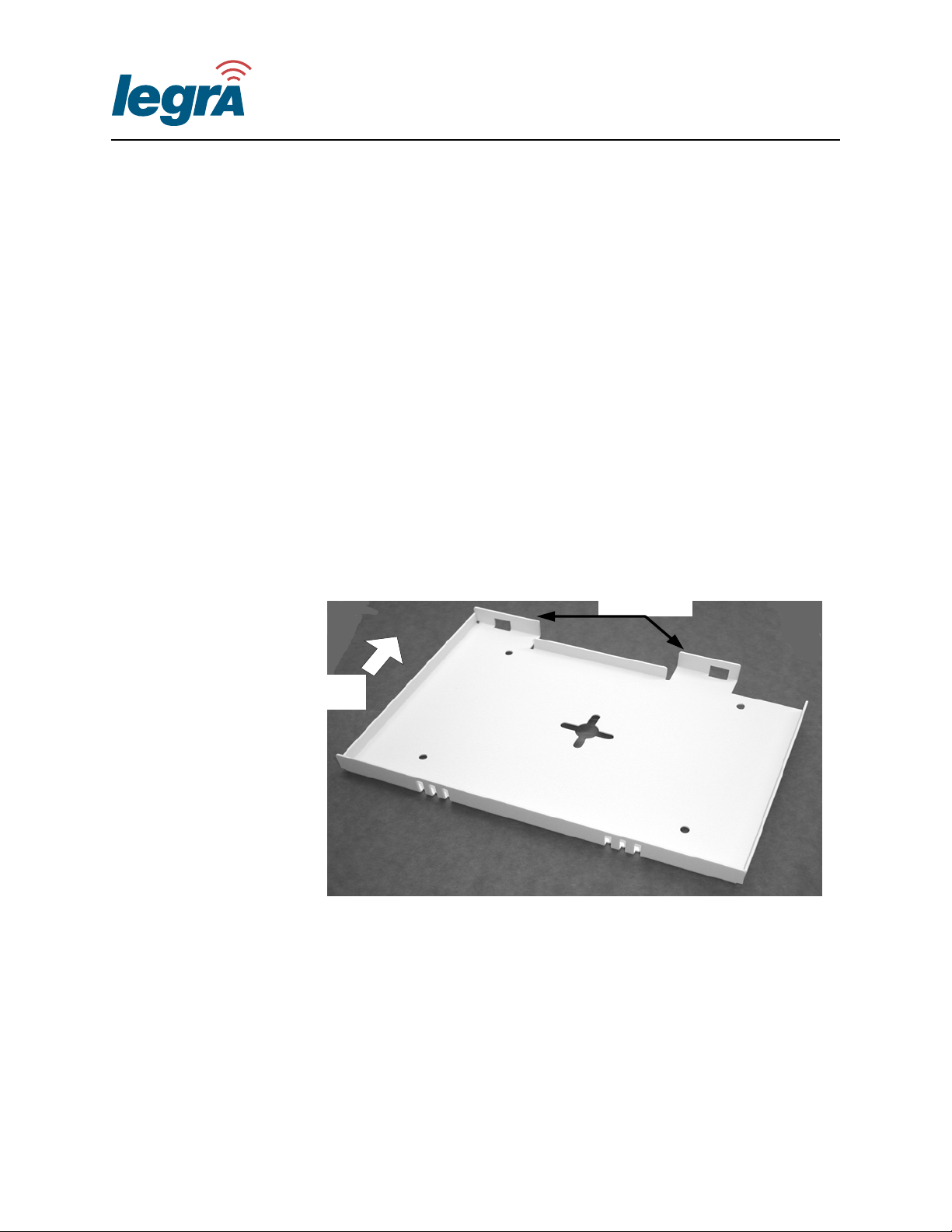
You can install the Legra Radio on horizontal or vertical flat surfaces,
such as walls or ceilings. The Legra Radio includes a separate
mounting bracket. You can install the mounting bracket with screws, or
wall anchors and screws. Use the mounting bracket as a template to
mark the locations for the attaching hardware.
Installing the Mounting Bracket
You can install the mounting bracket on a horizontal or vertical surface,
such as a ceiling or wall.
Mounting
Flanges
18 Overview
UP
Figure 3-1 Legra Radio LR11b Mounting Bracket
Use the holes in the mounting bracket as a template to mark the
locations of the attaching hardware. If necessary, you can use the
provided wall anchors to secure bracket to the surface.
Legra Systems Inc. Proprietary and Confidential
Page 31

009-10602-A Legra Radio Installation Guide
CAUTION Do not install the Legra Radio upside down. Otherwise, damage to the
unit may occur.
If you are installing the Legra Radio on a vertical surface, ensure that
the top mounting flanges are oriented up or to the side. The bracket’s
mounting flanges support the weight of the Legra Radio.
To install the mounting bracket
1 Mark the locations of the four mounting holes using the mounting
bracket as a template.
2 If using the wall anchors, install the wall anchors in the four
mounting hole locations.
3 Install the mounting bracket using four screws.
The mounting bracket is installed.
Attaching the Legra Radio to the Mounting Bracket
You can connect the Legra Radio to the mounting bracket with the
following procedure.
To attach the Legra Radio to the mounting bracket
1 Install the Legra Radio’s aft mounting slots on to the mounting
flanges. Be sure that the LR11b hooks engage the bracket slots.
2 Press the front of the Legra Radio to secure it to the mounting
bracket. You should hear the Legra Radio snap into place.
Legra Systems Inc. Proprietary and Confidential
Mounting Instructions 19
Page 32

Legra Radio Installation Guide 009-10602-A
Removing the Legra Radio from the Mounting Bracket
You can remove the Legra Radio from the mounting bracket with the
following procedure.
To remove the Legra Radio from the mounting bracket
1 Push the Legra Radio from front toward the aft of the unit. This
decouples the hooks from the bracket’s mounting flanges.
2 Pull the aft portion or the Legra Radio away from the bracket and
remove the Legra Radio from the mounting bracket.
The Legra Radio is removed from the bracket.
Imprinting a Legra Radio
You can physically connect your Legra Radio to a network device other
than a Legra Switch. However, before connecting, you must imprint the
Legra Radio with information from a Legra Switch LS2012. Imprinting
transfers the Legra Switch’s DNS information on to the Legra Radio,
allowing you to route IP packets to and from the Legra Radio across
your network to the remote Legra Switch.
The imprinting process begins when you plug the Legra Radio into a
Legra Switch with a category 5 Ethernet cable. The Legra Switch sends
Power over Ethernet and DNS information to the Legra Radio. The
Legra Radio’s Power LED blinks slowly during the imprinting process
and becomes solid green when imprinting is complete.
When imprinting is complete, you can disconnect the Legra Radio,
install it, and connect it to your network device. You must then
configure your network so that the Legra Switch and Legra Radio
transmit IP packets to one another through your network. You can
remove the imprinted information when you hold down the RESET
button for several seconds. After RESET, you must then connect the the
Legra Radio to imprint information from another Legra Switch.
20 Overview
Legra Systems Inc. Proprietary and Confidential
Page 33

009-10602-A Legra Radio Installation Guide
To imprint LS2012 information on a Legra Radio
1 Connect a category 5 Ethernet cable to the Legra Switch 10/100
Ethernet port.
2 Connect the cable to the Legra Radio’s RJ-45 Ethernet Port.
The green Legra Radio Power LED blinks slowly. The LED turns
solid green when imprinting is complete.
The Legra Radio is imprinted.
Connecting Power to the Legra Radio
Use one of the following methods to provide power to the Legra Radio:
• Power over Ethernet (PoE)
• Inline Power Injector
• Power Brick
Power over Ethernet (PoE)
If you connect a Legra Radio directly to a Legra Switch, the Legra
Radio operates on PoE from the Legra Switch. After you connect a
category 5 Ethernet cable to your Legra Switch, additional power
connections are not required.
You can also connect your Legra Radio to a third party switch. If the
third party switch does not support PoE, use an inline power injector or
power brick to power the Legra Radio. If the third party switch supplies
Power over Ethernet, additional power connections are not required.
Legra Systems Inc. Proprietary and Confidential
Mounting Instructions 21
Page 34
Legra Radio Installation Guide 009-10602-A
Inline Power Injector
If your third party switch does not support PoE, you can place a power
injector inline between the switch port and the Legra Radio. See your
power injector documentation for installation and usage instructions.
Power Brick
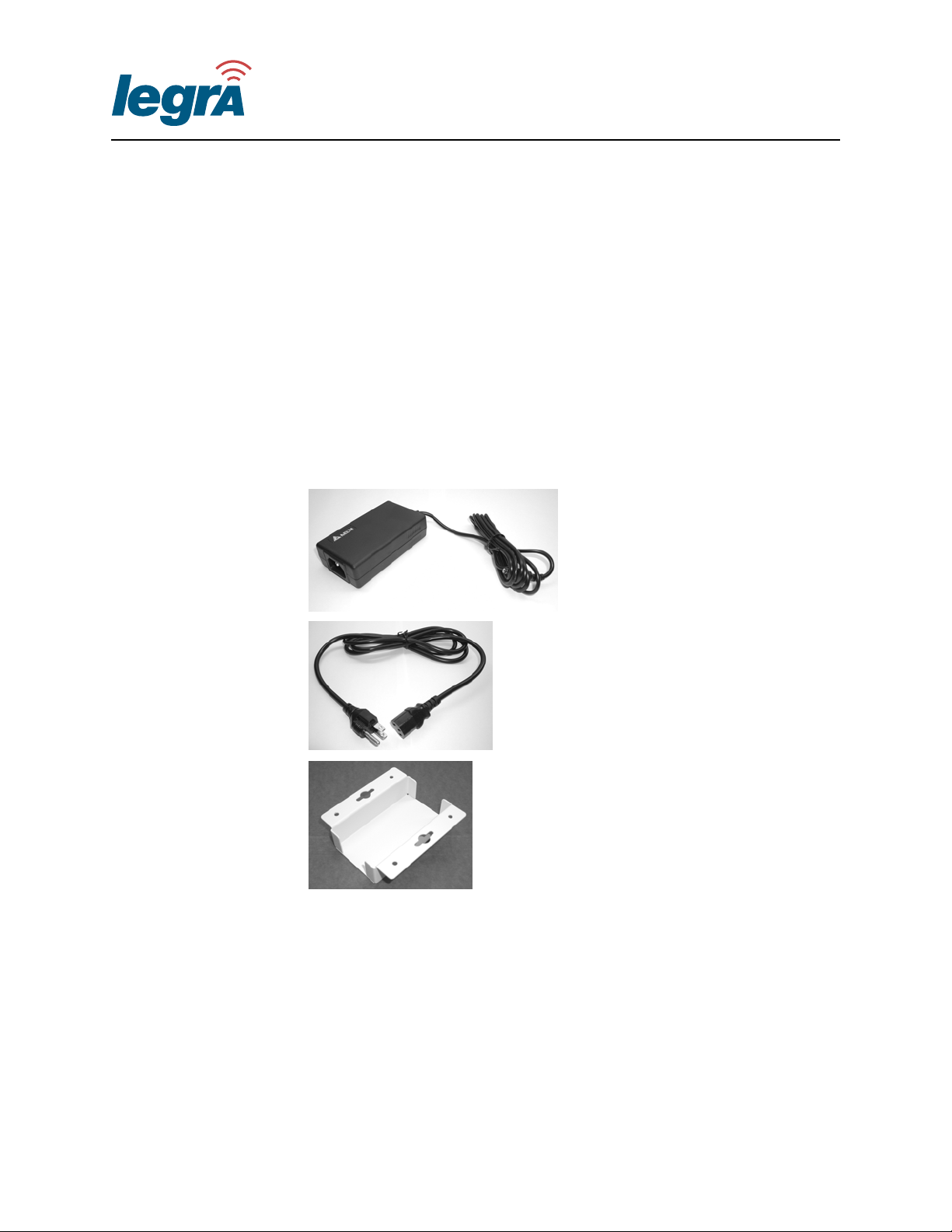
If a power injector cannot be used, use a power brick (Figure 3-2) to
power the Legra Radio.
Power Brick
22 Overview
Power Cord
Mounting Bracket
Figure 3-2 Legra Radio Power Brick (Sold Separately)
The power brick connects to a wall outlet at one end and the Legra
Radio 5V DC Power Socket at the other. The power brick must be
located within a 2 foot radius of the Legra Radio.
The Legra power brick and mounting bracket are sold separately.
Contact your Legra System Inc representative for more information.
Legra Systems Inc. Proprietary and Confidential
Page 35
Specifications
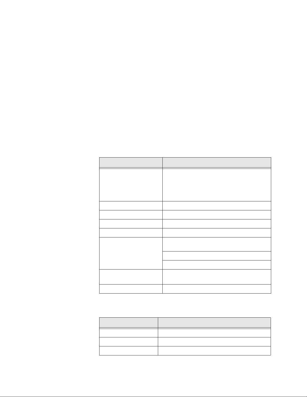
Table A-1 Performance Specifications
Name Description
FCC/IC: 1-11
ETSI: 1-13
802.11b
Maximum Clients 64
France: 10-13
Spain: 10-11
MKK: 1-14
A
Operating Range Up to 500 m (1640 ft)
Data Rate Normal Mode: 1, 2, 5.5, 11 Mbps per channel
Network Configuration Infrastructure
5.15 ~ 5.25 GHz (lower band) US/Canada,
Japan
Operating Frequency
Power supply
Output Power 16 dBm minimum
Table A-2 General Specifications
Characteristic Specification
Physical Size 20.5 × 13.6 × 4 cm, (8.07 × 5.35 × 1.58 in)
Weight 280 grams (9.9 oz)
LED Indicators See “LED Indicators” on page 4.
5.25 ~ 5.35 GHz (middle band) US/Canada
5.725 ~ 5.825 GHz (upper band) US/Canada
Input: 100-240 AC, 50-60 Hz
Output: 5 VDC, 3 A
Legra Systems Inc. Proprietary and Confidential
A-1
Page 36
Legra Radio Installation Guide 009-10602-A
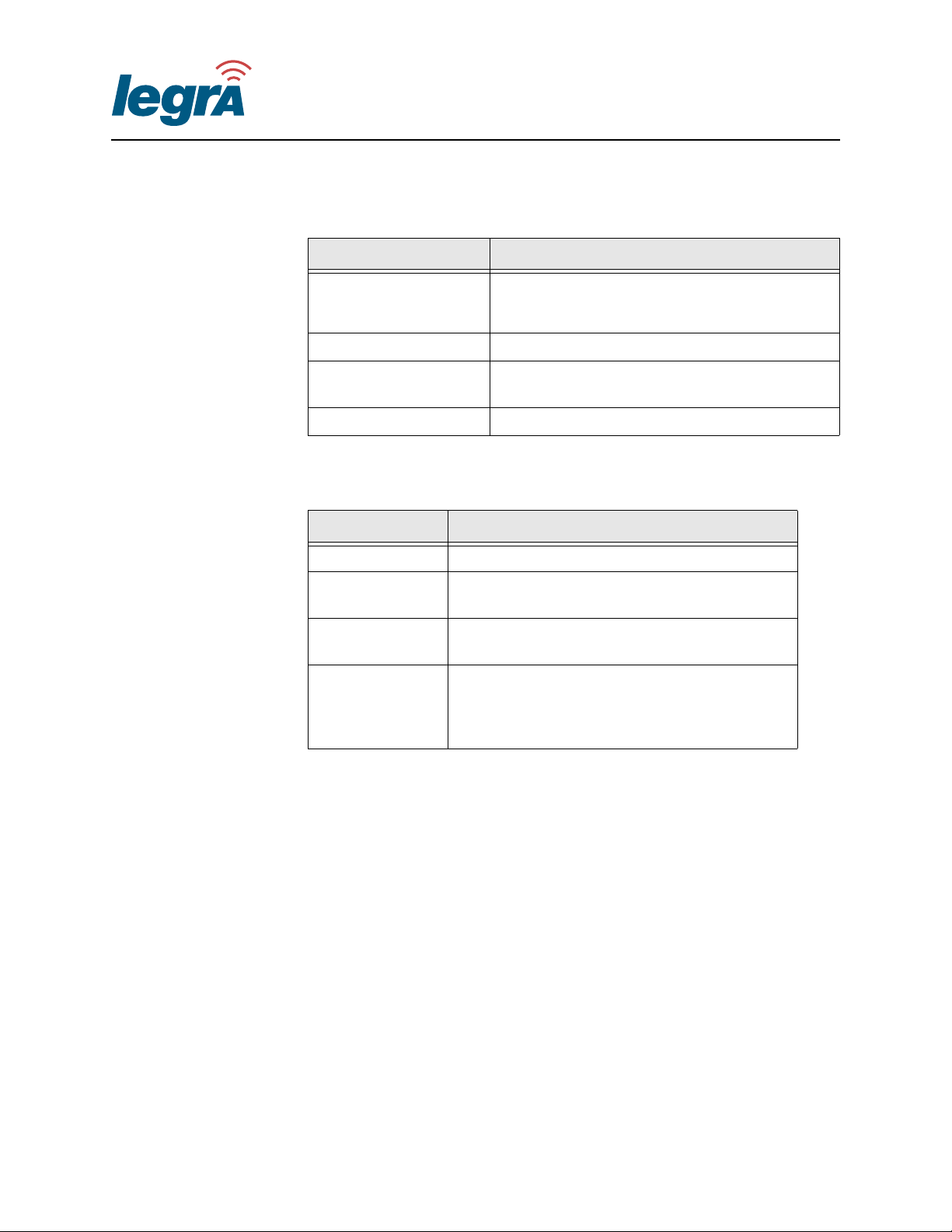
Table A-2 General Specifications
Characteristic Specification
Legra Manager LM6000 Network Management
Network Management
Operating Systems Windows 98/Me/NT/2000/XP
System
Legra Switch LS2012 User Interface
Temperature
Humidity 5% to 95% (non-condensing)
Operating: 0 to 50 ºC (32 to 122 ºF)
Storage: 0 to 70 ºC (32 to 158 ºF)
Table A-3 Compliances
Category Standard
Compliances IEC 61000-4-2/3/4/6/11
Emissions
Safety
Standards
FCC Class B
RCR STD-33A
CSA/NTRL (CSA 22.2 No. 950 & UL 1950)
EN60950 (TUV/GS), IEC60950 (CB)
IEEE 802.3 10BASE-T
IEEE 802.3u 100BASE-TX
IEEE 802.11a/b
IEEE 802.3af PoE
A-2
Legra Systems Inc. Proprietary and Confidential
Page 37

Contact Information
Legra Systems, Inc.
3 Burlington Woods Drive
Burlington, MA 01803-4543
Tel: (781) 272-8400
Fax: (781) 272-8401
Website: http:\\www.legra.com
Legra Systems Inc. Proprietary and Confidential
Page 38

Legra Systems, Inc.
3 Burlington Woods Drive
Burlington, MA 01803-4543
Tel: (781) 272-8400
Fax: (781) 272-8401
Website: http:\\www.legra.com
009-10602-A
©2003 Legra Systems. All rights reserved.
Legra Systems Inc. Proprietary and Confidential
 Loading...