

Page 1
LEESON
SPEEDMASTER
DC MOTOR
ADJUSTABLE SPEED
CONTROL
INSTALLATION
AND OPERATING
INSTRUCTIONS
THIS BOOK COVERS LOW VOLTAGE CONTROL CATALOG NUMBERS
175135.00REV1 and 175136.00REV1
Page 2

INSTALLATION and OPERATING INSTRUCTIONS
FOR CATALOG NUMBERS 175135.00REV1 AND 175136.00REV1
SPEEDMASTER™ ADJUSTABLE SPEED CONTROLS for
BATTERY POWERED EQUIPMENT UP TO 60 AMPS
TABLE OF CONTENTS
STANDARD FEATURES ....................................................................... 2
CONTROL DIMENSIONS ..................................................................... 2
MODEL SELECTION ............................................................................ 2
MOUNTING DIMENSIONS ................................................................... 3
INSTALLATION & HOOK-UP ............................................................... 3
STANDARD HOOK-UP DIAGRAM....................................................... 4
REVERSING HOOK-UP DIAGRAM ..................................................... 4
INHIBIT CIRCUIT .................................................................................. 4
TRIMPOT ADJUSTMENTS ................................................................... 5
IN CASE OF DIFFICULTY .................................................................... 6
SPECIFICATIONS................................................................................. 6
SCHEMATIC DIAGRAM ....................................................................... 7
DISCLAIMER ........................................................................................ 8
WARRANTY .......................................................................................... 9
1
Page 3
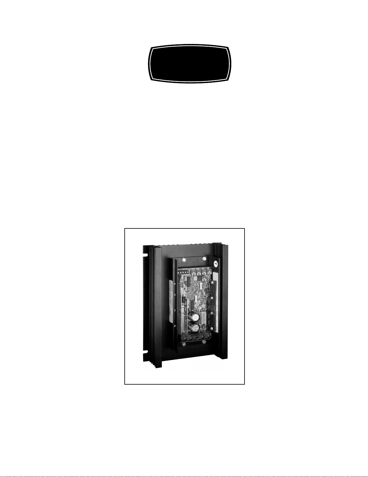
STANDARD FEATURES
• Provides smooth variable speed capability for mobile equipment.
• Maintains variable speed control as batteries discharge.
• Adjustable min speed, max speed, i.r. compensation, current limit, and accel.
• Inhibit terminal permits optional start-stop without breaking battery lines.
• Speed potentiometer, knob, and dialplate included.
• Increases range OR running time of battery operated equipment through high
efficiency.
• Automatic current limit foldback decreases current limit to 50% of setpoint when
heatsink temperatures reach 80° C. - provides protection from overheating.
DIMENSIONS
MODEL WIDTH LENGTH DEPTH WEIGHT
INCHES (CENTIMETERS) OZ. (g.)
175135 6.7 (17.1) 9.0 (22.9) 2.27 (5.77) 34.0 (962)
175136 6.7 (17.1) 9.0 (22.9) 2.27 (5.77) 34.0 (963)
MODEL SELECTION
CONTINUOUS CURRENT MODEL NUMBER
(12VDC INPUT ± 15%) (0 - 12VDC OUTPUT)
60
(24/36VDC INPUT ± 15%) (0 - 24/36VDC OUTPUT)
60
WARNING:
MAKE CERTAIN THAT THE POWER SUPPLY IS DISCONNECTED BEFORE ATTEMPTING TO SERVICE
OR REMOVE ANY COMPONENTS!!! IF THE POWER DISCONNECT POINT IS OUT OF SIGHT, LOCK IT
IN DISCONNECTED POSITION AND TAG TO PREVENT UNEXPECTED APPLICATION OF POWER.
175135
175136
ONLY A QUALIFIED ELECTRICIAN OR SERVICEMAN SHOULD PERFORM ANY ELECTRICAL
TROUBLESHOOTING OR MAINTENANCE.
AT NO TIME SHOULD CIRCUIT CONTINUITY BE CHECKED BY SHORTING TERMINALS WITH A
SCREWDRIVER OR OTHER METAL DEVICE.
2
Page 4
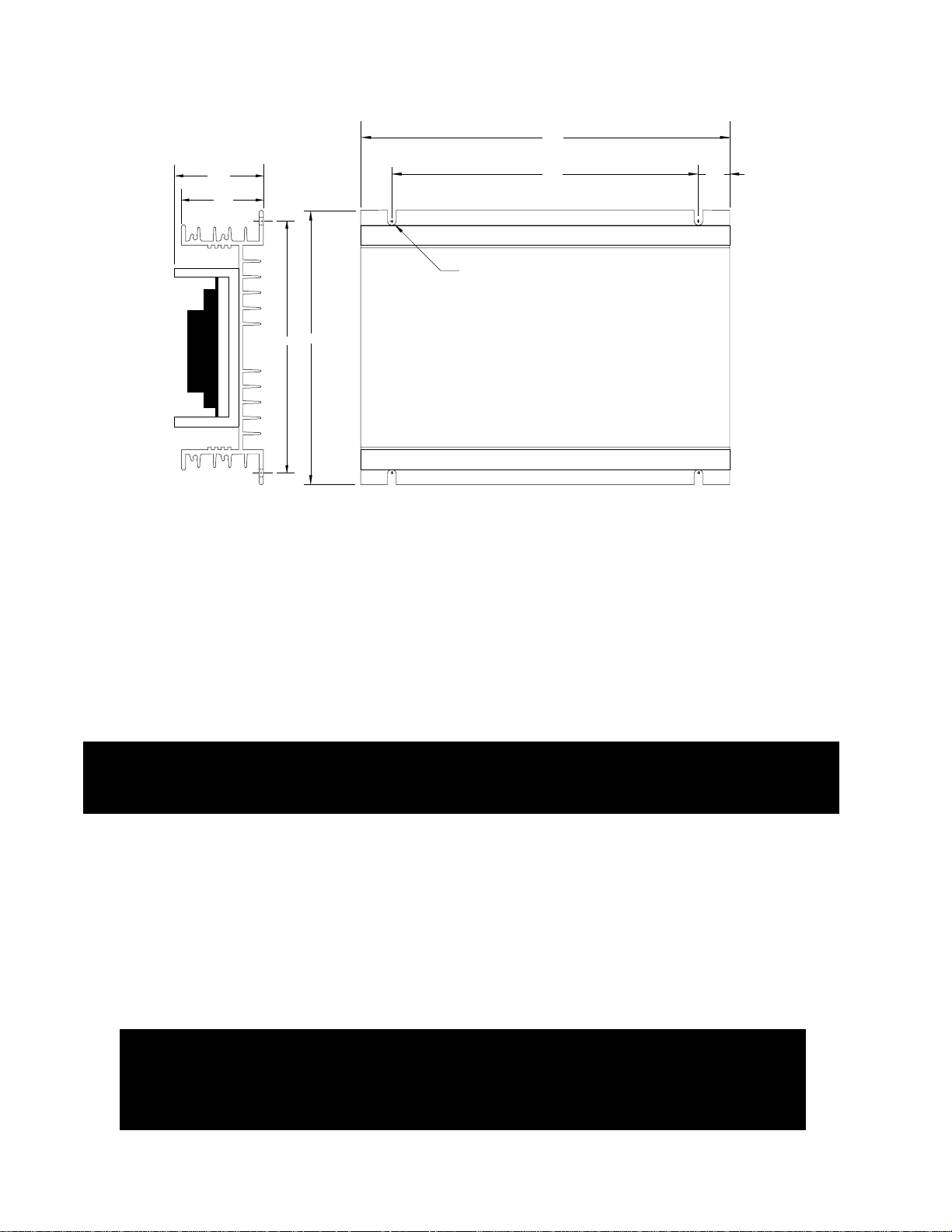
175135.00REV1 / 175136.00REV1 MOUNTING
9.00”
2.27”
2.00”
6.30”
6.70”
7.50”
7/32” DIA.
(4 SLOTS)
When mounting the control, allow clearance above
NOTE:
components to prevent shorting
.75”
CAUTION: DO NOT MOUNT CONTROLLER WHERE AMBIENT TEMPERATURE IS
OUTSIDE THE RANGE OF -10° C (15° F) TO 45° C ( 115° F).
INSTALLATION & HOOK-UP
Before attempting to wire the control, make sure all power is disconnected. Recheck code
designation to assure proper voltage is present for the control. Caution should be used in
selecting proper size of hook-up wire for current and voltage drop. Note: The battery and
armature wire size on 175135.00REV1 and 175136.00REV1 models must be a minimum of 12
gauge.
Warning:
Do not reverse positive or negative battery leads, this will damage the control. To
change motor direction, interchange the positive and negative Armature leads.
Refer to the following wiring diagrams for proper location when connecting DC Voltage,
Armature, and Speedpot wires to the control.
CAUTION !! TURN POWER OFF WHILE MAKING CONNECTIONS.
To properly adjust the CURRENT LIMIT setting, a DC ammeter should be placed in series with
the armature line. This meter can be removed after the control is adjusted.
Warning:
Improper installation or operation of this control may cause injury to
personnel or control failure. The control must be installed and grounded
in accordance with local, state, and national safety codes.
3
Page 5

175135.00REV1 / 175136.00REV1 HOOKUP DIA GRAMS
+
-
Battery
Caution:
Motor and battery wire must
be a minimum of 12 ga. and
a maximum of 6 ga.
White
Motor
Customer supplied
3PDT Center-off
Center-blocked switch
Relays may be used in place of switch, but a neutral position must be provided
to prevent plug reversing. Do not engage opposite direction until motor has
come to a complete stop. Failure to do so may result in damage to the control.
Pot High (P2-1)
Pot Wiper (P2-2)
Pot Low (P2-3)
Common (P2-4)
Inhibit (P2-5)
+Arm (P1-5)
+Battery (P1-4)
No Connect (P1-3)
-Arm (P1-2)
-Battery (P1-1)
5KΩ
Speedpot
Orange
Red
Current Limit
Max Speed
Accel
I.R. Comp.
Min Speed
++
Optional
Inhibit
(see hook-up
below)
Customer
supplied
SPST switch
++
P1
P2
++
-
-
Battery
Motor
+
Motor and battery wire must
be a minimum of 12 ga. and
+
Customer supplied
SPST switch
Caution:
a maximum of 6 ga.
175135.00REV1 / 175136.00REV1 REVERSING HOOKUP
175135.00REV1 / 175136.00REV1 HOOKUP
Pot High (P2-1)
-Battery (P1-1)
-Arm (P1-2)
Pot Wiper (P2-2)
Pot Low (P2-3)
Common (P2-4)
Inhibit (P2-5)
No Connect (P1-3)
+Battery (P1-4)
Current Limit
+Arm (P1-5)
P1
CAUTION: DO NOT OPERATE CONTROL OUTSIDE THE
RECOMMENDED INPUT +/-10%
P2
White
Orange
I.R. Comp.
Accel
Max Speed
Min Speed
5KΩ
Speedpot
Red
Optional
Inhibit
(see hook-up
below)
Relays may be used in place of switch, but a neutral position must be provided to prevent plug reversing. DO NOT
ENGAGE OPPOSITE DIRECTION UNTIL MOTOR HAS COME TO A COMPLETE STOP. Failure to do so may
result in damage to the control.
INHIBITING THE CONTROL - There are two methods that may be used to shut down the output without having
to break the battery supply (ie. inhibit the control).
Pot Wiper (P2-2)
Common (P2-4)
Using inhibit input - provide fast start-
stop by bypassing accel/decel circuit
Pot High (P2-1)
Pot Low (P2-3)
Inhibit (P2-5)
SPST Switch
open = run
P2
close = stop
Inhibit via speedpot - provides starting and
Pot High (P2-1)
Pot Wiper (P2-2)
Pot Low (P2-3)
Common (P2-4)
Inhibit (P2-5)
4
stopping through accel/decel parameters
White
Red
P2
Orange
SPST Switch
open = stop
close = run
Speedpot
5KΩ
Page 6

TRIMPOT ADJUSTMENTS
Before power is applied, the speed potentiometer and trimpots should be preset as follows:
TRIMPOT PRESET
1. Rotate Speedpot fully CCW.
2. Rotate Max trimpot CW 1/2 way.
3. Rotate Current Limit trimpot fully CW.
4. Rotate Min trimpot fully CCW.
5. Rotate Accel trimpot CW 1/2 way.
6. Rotate I.R. trimpot fully CW.
DC power can now be applied to the system and the control adjusted as follows:
TRIMPOT ADJUSTMENT
7. Increase the MIN trimpot in a CW direction until the desired minimum speed is reached.
8. Turn the Speedpot fully CW and adjust the MAX trimpot until the desired maximum
speed is reached.
9. Adjust the ACCEL trimpot to achieve the desired soft start time. CW rotation will increase
accel time.
10.Rotate the CURRENT LIMIT trimpot fully CCW until the motor begins to stall. Apply a
full load to the motor and adjust the trimpot until a desired current setting is obtained.
11.Adjust I.R. trimpot CW 1/2 way. If motor RPM is inconsistent (jumpy), rotate I.R. trimpot
CCW until rotation is stable.
IMPORTANT: DO NOT EXCEED CURRENT LIMIT AMPERAGE RATING. (see below)
LEESON SPEEDMASTER™ low voltage controls = 60 AMP MAX
Adjustment is now complete for the 175135.00REV1 and 175136.00REV1 models
and the ammeter may be removed.
5
Page 7

IN CASE OF DIFFICULTY
If a newly installed control will not operate, it is likely that a terminal or connection is loose. Check to make sure
connections are secure and correct. If the control is still inoperative, refer to the following chart for reference:
PROBLEM POSSIBLE CAUSE(S) CORRECTIVE ACTION
MOTOR DOESN’T RUN * INCORRECT OR NO POWER INSTALL PROPER SERVICE
* SPEEDPOT SET AT ZERO ROTATE SPEEDPOT FULLY CW
* WORN MOTOR BRUSHES REPLACE MOTOR BRUSHES
* CURRENT LIMIT SET TOO LOW ADJUST CURRENT LIMIT POT CW
MOTOR “HUNTS” * MOTOR SPEED IS ABOVE SEE TRIMPOT ADJUSTMENTS
RATED SPEED ON PAGE 5
* I.R. COMP. TRIMPOT SET SEE TRIMPOT ADJUSTMENTS
TOO HIGH ON PAGE 5
MOTOR RUNS AT * LOOSE SPEEDPOT CONNECTIONS SECURE ALL CONNECTIONS
“FULL SPEED” * MIN OR MAX TRIMPOTS NOT SEE TRIMPOT ADJUSTMENTS
UNCONTROLLABLE PROPERLY ADJUSTED ON PAGE 5
* POSSIBLE CONTROL FAILURE SEND TO LEESON ELECTRIC CORP.
MOTOR ROTATES IN * MOTOR ARMATURE HOOKED UP REVERSE ARMATURE + AND WRONG DIRECTION BACKWARDS LEADS
MOTOR STALLS UNDER * CURRENT LIMIT TRIMPOT SEE TRIMPOT ADJUSTMENTS
A LIGHT LOAD IMPROPERLY ADJUSTED ON PAGE 5
SPECIFICATIONS
175135.00REV1 and 175136.00REV1 Models
Load current (continuous) 60 amps continuous
Input Voltage 12VDC ± 10% (model 175135) 24/36VDC ± 10% (model 175136)
Output Voltage 0-12VDC (model 175135) 0-24/36VDC (model 175136)
Speed adjustment 5K9 potentiometer or 0 to +10VDC input signal
Speed range 30 : 1
Overload capacity 200% for 10 seconds; 150% for one minute
Current limit adjustable 100% to 200% of full motor load, up to continuous current rating (page 5)
Acceleration adjustable - 0 to 10 seconds
Deceleration non-adjustable - 0.5 seconds
Maximum speed adjustable - 50 to 100% of base speed
Minimum speed adjustable - 30% of max speed
Connections barrier terminal block
Speed regulation 1% of base speed
Package configuration black anodized aluminum extrusion
Internal operating frequency approximately 1.6K Hertz
Thermal protection Current foldback at 80o C. heatsink temperature
6
Page 8

175135.00REV1 / 175136.00REV1 SCHEMATIC
+12V
12 VOLT VERSION CHANGES:
R1 ........................ 10W 1W
R6 ........................ 22K 1/8W
R31 ...................... 2.2K 1/8W
R35 ...................... 1K 1/8W
R42 ...................... 22K 1/8W
R48 ...................... 1K 1/8W
R49
100K
P1-3
R45
REMOTE
SPEEDPOT
5K
COM
P2-4
INHIBIT
P2-5
N.C.
+12V
HI
P2-1
WIPER
P2-2
LO
P2-3
R20
MIN
5K
CW
C14
.1µF
63V
R50
100K
+12V
8
2
-
U4-1
+
4
3
C13
.1µF
63V
R19
47K
C5
R18
.1µF
300K
63V
R21
82K
1
cw
I.R.
R32
5K
NOTES:
U1 - 40106
U2 - LM324
U3 - LM324
U4 - LM358
470K
1/2W
9
-
U3-3
+
10
R42
47K
D1
1N4005
C10
47µF
16V
MAX
R7
20K
cw
R44
150W
+12V
R17
ACCEL
CW
R16
R15
20K
250K
1%
8
R14
180K
+12V
R25
10K
R26
4.7K
+
14
U2-4
-
C3
.22µF
100V
C6
.22µF
100V
R12
100K
6
-
7
U3-2
+
5
R13
10K
R23
4.7K
+12V
4
10
+
U2-3
-
11
9
R24
6.8K
C4
.1µF
63V
D5
1N914B
C15
R27
12
13
.01µF
47K
100V
+12V
R28
10K
TEMP SWITCH
CW
C.L.
R29
R30
300K
20K
R9
220K
C9
8
.01µF
100V
R46
22K
7
U4-2
SW1
R31
4.7K
R47
680K
-
+
2.7K
D4
1N963B
R8
33K
+12V
6
5
R48
14
R11
10K
R43
1.2M
5
+
U2-2
-
6
D6
1N5233B
R10
47K
U3-4
R6
10K
+12V
+
-
7
D7
1N914B
R51
15K
1
12
13
R22
10K
R33
100K
C2
.1µF
63V
R5
470W
+12V
4
3
+
1
U3-1
-
11
2
C7
.1µF
63V
9
U1-4
- ARM
3
+
U2-1
-
2
R35
2.7K
1N4005
D3
1N5349B
R3
470W
47K
8
D2
R1
300W
5W
R2
47K
P1-5
C12
C11
1000uF
1000uF
50V
50V
R4
P1-2
R36
22W
R37
22W
R38
22W
2
R39
22W
4
6
R40
22W
10
R41
22W
12
R34
47K
.1µF
C8
.01µF
100V
+12V
14
1
U1-1
3
U1-2
5
U1-3
11
U1-5
13
U1-6
7
C1
63V
MOTOR
IRFZ44
G
IRFZ44
G
IRFZ44
G
IRFZ44
G
IRFZ44
G
IRFZ44
G
Q1
Q2
Q3
Q4
Q5
Q6
+A
LINE
+B
P1-4
G
Q7
IRFZ44
Q8
IRFZ44
D
G
S
Q9
IRFZ44
D
G
S
Q10
IRFZ44
D
S
D
G
S
-A
D
S
D
S
D
S
D
S
D
S
D
S
R
P1-1
7
-B
ALL RESISTORS 1/8W UNLESS NOTED OTHERWISE
Page 9

DISCLAIMER
The information and technical data in this manual are
subject to change without notice. LEESON Electric Corporation and its Divisions make no warranty of any kind with
regard to this material, including, but not limited to, the
implied warranties of merchantability and fitness for a
particular purpose. LEESON Electric Corporation and its
Divisions assume no responsibility for any errors that may
appear in this manual and make no commitment to update
or to keep current the information in this manual.
LEESON
SPEEDMASTER
LEESON
GRAFTON, WI 53024-0241 U.S.A. (262) 377-8810 FAX (262) 377-9025
ELECTRIC CORPORATION
8
Page 10

LIMITED WARRANTY
A. WARRANTY: LEESON Electric Corporation warrants that their products will be free
from defects in material and workmanship for a period of one (1) year from date of shipment
thereof. Within the warranty period LEESON Electric will repair or replace such products
which are returned to LEESON Electric or to the nearest Branch Office, with shipping
charges prepaid. At our option, all return shipments are F.O.B. LEESON Electric or its
Branch Office. This warranty will not apply to any product which has been subjected to
misuse, negligence; or misapplied; or repaired by unauthorized persons; or improperly
installed. LEESON is not responsible for removal, installation or any other incidental
expenses incurred in shipping the products to or from the repair point.
B. DISCLAIMER: The provisions of paragraph 'A' are LEESON'S sole obligation and
exclude all other warranties of MERCHANTABILITY or use, express or implied. We further
disclaim any responsibility whatsoever to the customer or to any other person for injury to
person, or damage to or loss of property of value, caused by any product which has been
subjected to misuse, negligence or accident; or misapplied; or modified or repaired by
unauthorized persons; or improperly installed.
C. LIMITATION of LIABILITY: In the event of any claim for breach of any of LEESON'S
obligations, whether express or implied, and particularly in the event of any claim of the
warranty contained in paragraph 'A', or any other warranties, express or implied, or claim
of liability, which might, despite paragraph 'B', be decided against us by any lawful authority,
LEESON Electric shall under no circumstances be liable for any consequential damages,
losses or expenses arising in connection with the use of, or inability to use, our product for
any purpose whatsoever. An adjustment made under the warranty does not void the
warranty, nor does it imply an extension of the original one (1) year warranty period.
Products serviced and/or parts replaced on a no charge basis during the warranty period
carry the unexpired portion of the original warranty only.
If for any reason any of the foregoing provisions shall be ineffective, the Company's liability
for damages arising out of its manufacture or sale of equipment, or use thereof, whether
such liability is based on warranty, contract, negligence, strict liability in tort or otherwise,
shall not in any event exceed the full purchase price of such equipment.
Any action against the Company based upon any liability or obligation arising hereunder
or under any law applicable to the sale of equipment or the use thereof, must be
commenced within one year after the cause of such action arises.
LEESON
SPEEDMASTER
9
Page 11

NOTES:
Bulletin #302 10/00
10
 Loading...