

LeCroy WaveJet 322A, WaveJet 314A, WaveJet 312A, WaveJet 332A, WaveJet 352A Getting Started Manual
Page 1
Getting Started
Manual
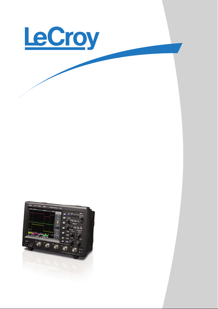
WaveJet®300A Series
Oscilloscopes
Page 2

L
L
E
E
C
C
RROOY
Y
W
AAVVE
W
O
SSCCIILLLLOOSSCCOOPPEES
O
GGEETTTTIINNGG SSTTAARRTTEEDD
E
J
J
SSEERRIIEES
MMAANNUUAALL
APRIL, 2009
EETT
330000A
S
A
S
Page 3
Manufactured under an
ISO 9000 Registered
Quality Management System
Visit www.lecroy.com to view
the certificate.
This electronic product is
subject to disposal and
recycling regulations that
vary by country and region.
Many countries prohibit the
disposal of waste electronic
equipment in standard waste
receptacles.
For more information about
proper disposal and
recycling of your LeCroy
product, please visit
www.lecroy.com/recycle.
LeCroy Corporation
700 Chestnut Ridge Road
Chestnut Ridge, NY 10977–6499
Tel: (845) 578 6020, Fax: (845) 578 5985
Internet: www.lecroy.com
© 2009 by LeCroy Corporation. All rights reserved.
LeCroy, ActiveDSO, JitterTrack, WaveLink, WavePro, WaveMaster, WaveSurfer,
WaveJet, and Waverunner are registered trademarks of LeCroy Corporation. Other
product or brand names are trademarks or requested trademarks of their respective
holders. Information in this publication supersedes all earlier versions. Specifications
subject to change without notice.
WJ-A-GS-E Rev A
917106-00 Rev A
Page 4

Getting Started Manual
INTRODUCTION ............................................................................... 7
SAFETY REQUIREMENTS .............................................................. 8
Safety Symbols and Terms ........................................................................................ 8
Operating Environment .............................................................................................. 9
Cooling Requirements ............................................................................................. 10
AC Power Source .................................................................................................... 10
Power and Ground Connections .............................................................................. 11
Calibration ............................................................................................................... 11
Cleaning .................................................................................................................. 11
Abnormal Conditions ............................................................................................... 12
WHEN YOUR SCOPE IS DELIVERED .......................................... 13
Check that You Have Everything ............................................................................. 13
Warranty.................................................................................................................. 13
Maintenance Agreements ........................................................................................ 13
SPECIFICATIONS .......................................................................... 15
Horizontal System ................................................................................................... 17
Acquisition System ................................ ................................ ................................ .. 17
Acquisition Processing ............................................................................................ 18
Trigger System ........................................................................................................ 18
Basic Triggers ......................................................................................................... 18
SMART Triggers ...................................................................................................... 18
Documentation and Connectivity ............................................................................. 18
Display .................................................................................................................... 19
Analog Persistence.................................................................................................. 19
Zoom ....................................................................................................................... 19
Internal Waveform Memory ..................................................................................... 19
Setup Storage ......................................................................................................... 19
Math Tools .............................................................................................................. 19
Measure Tools......................................................................................................... 20
General ................................................................................................................... 20
Max Input Range: ................................................................................. 16
POWER-UP AND INSTALLATION ................................................ 25
Power-Up ................................................................................................................ 25
Software .................................................................................................................. 25
Updating the System Software........................................................................ 26
PROBES ......................................................................................... 27
Probe Compensation ............................................................................................... 27
FRONT PANEL CONTROLS ......................................................... 28
Front Panel Buttons and Knobs ............................................................................... 28
WJ-A-GS-E Rev A iii
Page 5

WaveJet 300A Series
Trigger Controls .............................................................................................. 29
Horizontal Controls ......................................................................................... 29
Vertical Controls ............................................................................................. 30
Zoom Control Knobs ...................................................................................... 30
Special Features Controls .............................................................................. 31
General Control Buttons ................................................................................. 32
UNDERSTANDING DISPLAY INFORMATION ............................. 34
Grid Area ................................................................................................................. 34
Top Status Bar ........................................................................................................ 35
Bottom Status Bar ................................................................................................... 36
Message Line .......................................................................................................... 36
Trace Descriptors .................................................................................................... 36
TURNING ON TRACES ................................................................. 37
VERTICAL SETTINGS AND CHANNEL CONTROLS .................. 38
Choosing Coupling .................................................................................................. 38
Bandwidth Limiting .................................................................................................. 38
Probe Attenuation.................................................................................................... 38
Inverting Waveforms ............................................................................................... 39
Adjusting Sensitivity ................................................................................................ 39
Adjusting the Waveform's Position........................................................................... 40
SAMPLING MODES ....................................................................... 41
TIMEBASE SETUP ........................................................................ 41
TRIGGERING ................................................................................. 42
Trigger Types .......................................................................................................... 42
Pulse Width Triggering ................................................................................ 43
Period Triggering ............................................................................................ 44
Pulse Count Triggering ................................................................................... 45
TV Triggering.................................................................................................. 46
Horizontal Trigger Setup .......................................................................................... 47
Vertical .................................................................................................................... 47
To Set Up an Edge Trigger ............................................................................. 48
WAVEFORM MEASUREMENTS ................................................... 50
Measuring with Cursors ........................................................................................... 50
Cursor Measurement Selections ..................................................................... 50
Cursor Placement ........................................................................................... 51
PARAMETER MEASUREMENTS ................................................. 52
Measure Modes ...................................................................................................... 52
Standard Vertical Parameters ......................................................................... 52
Standard Horizontal Parameters ..................................................................... 53
iv WJ-A-GS-E Rev A
Page 6

Getting Started Manual
Other Parameters ........................................................................................... 54
Statistics .................................................................................................................. 54
DISPLAY FORMATS ...................................................................... 55
Display Setup .......................................................................................................... 55
Display Types .......................................................................................................... 56
Zooming Waveforms ............................................................................................... 56
Replay Mode ........................................................................................................... 57
SAVE AND RECALL ...................................................................... 58
Saving and Recalling Scope Settings ...................................................................... 58
Saving and Recalling Waveforms ............................................................................ 59
WAVEFORM MATH ....................................................................... 60
UTILITIES ....................................................................................... 61
Print Screen ............................................................................................................ 61
Configuration -- Page 1/2......................................................................................... 62
Configuration -- Page 2/2......................................................................................... 63
Calibration ............................................................................................................... 64
Status & Update ...................................................................................................... 65
WJ-A-GS-E Rev A v
Page 7

WaveJet 300A Series
BLANK PAGE
6 WJ-A-GS-E Rev A
Page 8

Getting Started Manual
INTRODUCTION
This brief guide includes important safety and installation information for your WaveJet
Series oscilloscope, along with brief operating procedures to get you started capturing,
viewing, and analyzing your waveforms.
WJ-A-GS-E Rev A 7
Page 9
WaveJet 300A Series
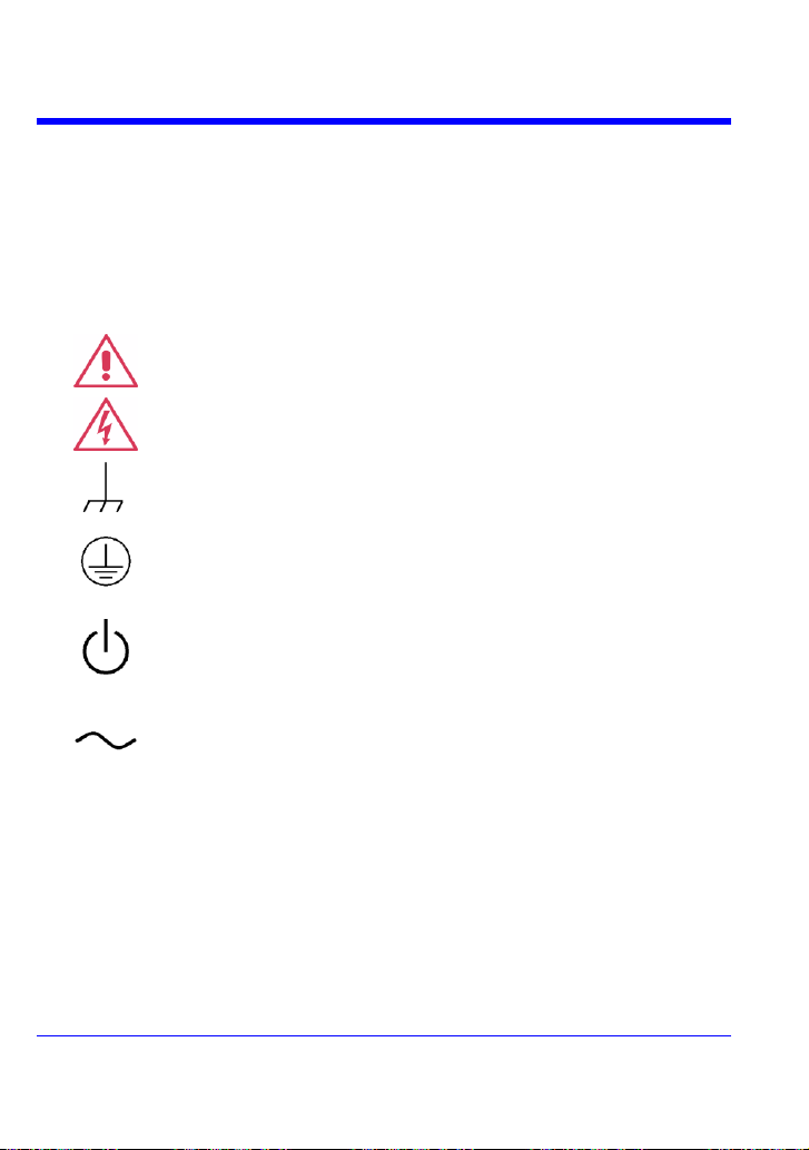
This symbol is used where caution is required. Refer to the
accompanying information or documents in order to protect against
personal injury or damage to the instrument.
This symbol warns of a potential risk of shock hazard.
This symbol is used to denote the measurement ground connection.
This symbol is used to denote a safety ground connection.
This symbol shows that the switch is a On/Standby switch. When it is
pressed, the scope’s state toggles between Operating and Standby
state. This switch is not a disconnect device. To completely remove
power to the scope, the power cord must be unplugged from the AC
outlet after the scope is placed in Standby state.
This symbol is used to denote "Alternating Current."
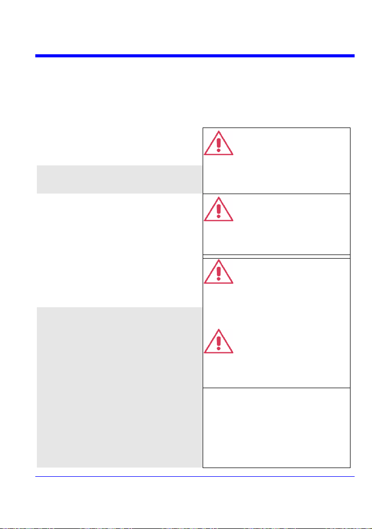
CAUTION
The CAUTION sign indicates a potential hazard. It calls attention to a
procedure, practice or condition which, if not followed, could possibly
cause damage to equipment. If a CAUTION is indicated, do not
proceed until its conditions are fully understood and met.
WARNING
The WARNING sign indicates a potential hazard. It calls attention to
a procedure, practice or condition which, if not followed, could
possibly cause bodily injury or death. If a WARNING is indicated, do
not proceed until its conditions are fully understood and met.
SAFETY REQUIREMENTS
This section contains information and warnings that must be observed to keep the
instrument operating in a correct and safe condition. You are required to follow
generally accepted safety procedures in addition to the safety precautions specified in
this section.
Safety Symbols and Terms
Where the following symbols or terms appear on the instrument’s front or rear panels,
or in this manual, they alert you to important safety considerations.
8 WJ-A-GS-E Rev A
Page 10
Getting Started Manual
CAT I
Installation (Overvoltage) Category rating per EN 61010-1 safety
standard and is applicable for the oscilloscope front panel measuring
terminals. CAT I rated terminals must only be connected to source
circuits in which measures are taken to limit transient voltages to an
appropriately low level.
The instrument is intended for indoor use
and should be operated in a clean, dry
environment.
Note: Direct sunlight, radiators, and other
heat sources should be taken into account
when assessing the ambient temperature.
WARNING
The scope must not be operated in
explosive, dusty, or wet/damp
atmospheres.
The design of the instrument has been
verified to conform to EN 61010-1 safety
standard per the following limits:
Installation (Overvoltage) Categories II
(Mains Supply Connector) & I (Measuring
Terminals)
Pollution Degree 2
Protection Class I
Note:
Installation (Overvoltage) Category II refers
to local distribution level, which is applicable
to equipment connected to the mains supply
(AC power source).
Installation (Overvoltage) Category I refers
to signal level, which is applicable to
equipment measuring terminals that are
connected to source circuits in which
measures are taken to limit transient
voltages to an appropriately low level.
Pollution Degree 2 refers to an operating
environment where normally only dry nonconductive pollution occurs. Occasionally a
CAUTION
Protect the scope’s display touch
screen from excessive impacts with
foreign objects.
CAUTION
Do not exceed the maximum specified
front panel terminal (CH1, CH2, CH3,
CH4, EXT) voltage levels. Refer to
Specifications for more details.
CAUTION
Do not connect or disconnect probes or
test leads while they are connected to a
voltage source.
Operating Environment
WJ-A-GS-E Rev A 9
Page 11
WaveJet 300A Series
temporary conductivity caused by
condensation must be expected.
Protection Class 1 refers to a grounded
equipment, in which protection against
electric shock is achieved by Basic
Insulation and by means of a connection to
the protective ground conductor in the
building wiring.
The instrument relies on forced air cooling
with internal fans and ventilation openings.
Care must be taken to avoid restricting the
airflow around the apertures (fan holes) at
each side of the scope. To ensure adequate
ventilation it is required to leave a10 cm (4
inch) minimum gap around the sides of the
instrument.
CAUTION
Do not block the ventilation holes
located on both sides of the scope.
CAUTION
Do not allow any foreign matter to enter
the scope through the ventilation holes,
etc.
The instrument operates from a singlephase, 100 to 240 V
rms
(+/-10%) AC power
source at 50/60 Hz (+/-5%), or single-phase
100 to 120 V
rms
(+/-10%) AC power source at
400 Hz (+/-5%).
No manual voltage selection is required
because the instrument automatically adapts
to line voltage.
Depending on the accessories installed (PC
port plug-ins, Ethernet & GPIB options, etc.),
the instrument can draw up to 75 W (75 VA).
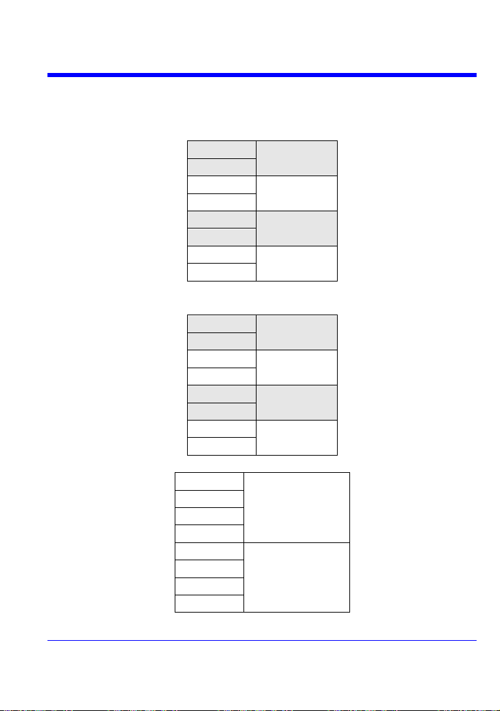
Note:
The instrument automatically adapts
itself to the AC line input within the
following ranges:
Voltage
Range:
90 to 264 V
rms
90 to 132 V
rms
Frequency
Range:
47 to 63 Hz
380 to 420 Hz
Cooling Requirements
AC Power Source
10 WJ-A-GS-E Rev A
Page 12
Getting Started Manual
The instrument is provided with a grounded
cord set containing a molded three-terminal
polarized plug and a standard IEC320 (Type
C13) connector for making line voltage and
safety ground connection. The AC inlet
ground terminal is connected directly to the
frame of the instrument. For adequate
protection against electrical shock hazard,
the power cord plug must be inserted into a
mating AC outlet containing a safety ground
contact. Use only the power cord specified
for this instrument and certified for the
country of use.
WARNING
Electrical Shock Hazard!
Any interruption of the protective
conductor inside or outside of the
scope, or disconnection of the safety
ground terminal creates a hazardous
situation.
Intentional interruption is prohibited.
The scope should be positioned to allow
easy access to the socket-outlet. To
completely remove power to the scope,
unplug the instrument’s power cord from the
AC outlet.
It is recommended that the power cord be
unplugged from the AC outlet if the scope is
not to be used for an extended period of
time.
CAUTION
The outer shells of the front panel
terminals (CH1, CH2, CH3, CH4, EXT)
are connected to the instrument’s
chassis and therefore to the safety
ground.
Clean only the exterior of the instrument,
using a damp, soft cloth. Do not use
chemicals or abrasive elements. Under no
circumstances allow moisture to penetrate
the instrument. To avoid electrical shock,
unplug the power cord from the AC outlet
before cleaning.
WARNING
Electrical Shock Hazard!
No operator serviceable parts inside.
Do not remove covers.
Refer servicing to qualified personnel.
Power and Ground Connections
Calibration
The recommended calibration interval is one year. Calibration should be performed by
qualified personnel only.
Cleaning
WJ-A-GS-E Rev A 11
Page 13
WaveJet 300A Series
Operate the instrument only as intended by
the manufacturer.
If you suspect the scope’s protection has
been impaired, disconnect the power cord
and secure the instrument against any
unintended operation.
The scope’s protection is likely to be
impaired if, for example, the instrument
shows visible damage or has been subjected
to severe transport stresses.
Proper use of the instrument depends on
careful reading of all instructions and labels.
WARNING
Any use of the scope in a manner not
specified by the manufacturer may
impair the instrument’s safety
protection.
Abnormal Conditions
12 WJ-A-GS-E Rev A
Page 14

Getting Started Manual
WHEN YOUR SCOPE IS DELIVERED
Check that You Have Everything
First, verify that all items on the packing list or invoice copy have been shipped to you.
Contact your nearest LeCroy customer service center or national distributor if anything
is missing or damaged. If there is something missing or damaged, and you do not
contact us immediately, we cannot be responsible for replacement.
: THE WARRANTY BELOW REPLACES ALL OTHER WARRANTIES,
NNOOTTEE:
EXPRESSED OR IMPLIED, INCLUDING BUT NOT LIMITED TO ANY IMPLIED
WARRANTY OF MERCHANTABILITY, FITNESS, OR ADEQUACY FOR ANY
PARTICULAR PURPOSE OR USE. LECROY SHALL NOT BE LIABLE FOR ANY
SPECIAL, INCIDENTAL, OR CONSEQUENTIAL DAMAGES, WHETHER IN
CONTRACT OR OTHERWISE. THE CUSTOMER IS RESPONSIBLE FOR THE
TRANSPORTATION AND INSURANCE CHARGES FOR THE RETURN OF
PRODUCTS TO THE SERVICE FACILITY. LECROY WILL RETURN ALL
PRODUCTS UNDER WARRANTY WITH TRANSPORT PREPAID.
Warranty
The oscilloscope is warranted for normal use and operation, within specifications, for a
period of three years from shipment. LeCroy will either repair or, at our option, replace
any product returned to one of our authorized service centers within this period.
However, in order to do this we must first examine the product and find that it is
defective due to workmanship or materials and not due to misuse, neglect, accident, or
abnormal conditions or operation.
LeCroy shall not be responsible for any defect, damage, or failure caused by any of the
following: a) attempted repairs or installations by personnel other than LeCroy
representatives or b) improper connection to incompatible equipment, or c) for any
damage or malfunction caused by the use of non-LeCroy supplies. Furthermore,
LeCroy shall not be obligated to service a product that has been modified or integrated
where the modification or integration increases the task duration or difficulty of
servicing the oscilloscope. Spare and replacement parts, and repairs, all have a 90-day
warranty.
The oscilloscope’s firmware has been thoroughly tested and is presumed to be
functional. Nevertheless, it is supplied without warranty of any kind covering detailed
performance. Products not made by LeCroy are covered solely by the warranty of the
original equipment manufacturer.
Maintenance Agreements
We offer a variety of services under the heading of Maintenance Agreements. These
give extended warranty and allow you to budget maintenance costs after the initial
three-year warranty has expired. Installation, training, enhancements, and on-site
WJ-A-GS-E Rev A 13
Page 15

WaveJet 300A Series
repairs, among other services, are available through special supplemental support
agreements. Inquire at your LeCroy customer service center or national distributor.
14 WJ-A-GS-E Rev A
Page 16
Getting Started Manual
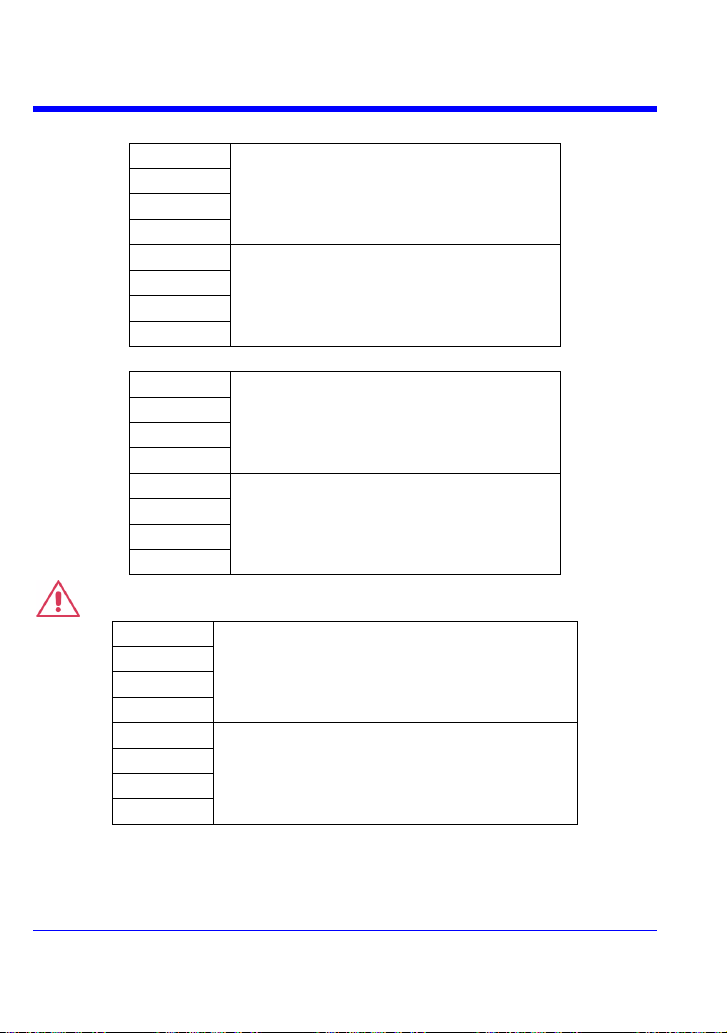
WJ354A
500 MHz
WJ352A
WJ334A
350 MHz
WJ332A
WJ324A
200 MHz
WJ322A
WJ314A
100 MHz
WJ312A
WJ354A
750 ps
WJ352A
WJ334A
1.00 ns
WJ332A
WJ324A
1.75 ns
WJ322A
WJ314A
3.50 ns
WJ312A
WJ354A
20 MHz/100 MHz
WJ352A
WJ334A
WJ332A
WJ324A
20 MHz
WJ322A
WJ314A
WJ312A
SPECIFICATIONS
Vertical System
Bandwidth (-3 dB @ 50 ohms):
Input Channels: 4 (WJ354A/334A/324A/314A); 2 (WJ352A/332A/322A/312A)
Rise Time (typical):
Bandwidth Limiters:
WJ-A-GS-E Rev A 15
Page 17
WaveJet 300A Series
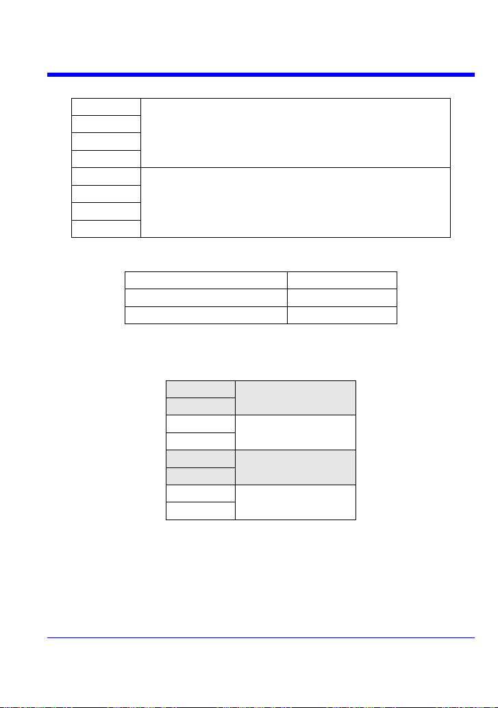
WJ354A
1 Mohm+/-1.5 % || 16 pF, 50 ohm +/-1.5 %
WJ352A
WJ334A
WJ332A
WJ324A
1 Mohm+/-1.5 % || 20 pF
WJ322A
WJ314A
WJ312A
WJ354A
GND, DC1Mohm, AC1Mohm, DC50ohm
WJ352A
WJ334A
WJ332A
WJ324A
GND, DC1Mohm, AC1Mohm
WJ322A
WJ314A
WJ312A
WJ354A
+/-400 Vpk CAT I (1 Mohms), 5 V
rms
(50 ohms)
WJ352A
WJ334A
WJ332A
WJ324A
+/-400 Vpk CAT I (1 Mohms)
WJ322A
WJ314A
WJ312A
Input Impedance:
Input Coupling:
Max Input Range:
Vertical Resolution: 8-bit
16 WJ-A-GS-E Rev A
Page 18
Getting Started Manual
WJ354A
2 mV/div~10 V/div (1 Mohms), 2 mV/div~2 V/div (50 ohms)
WJ352A
WJ334A
WJ332A
WJ324A
2 mV/div~10 V/div (1 Mohms)
WJ322A
WJ314A
WJ312A
2 mV/div~50 mV/div
+/-1 V
50.2m V/div~500m V/div
+/-10 V
502 mV/div~10 V/div
+/-100 V
WJ354A
500 ps/div - 50 s/div
WJ352A
WJ334A
1 ns/div - 50 s/div
WJ332A
WJ324A
2 ns/div - 50 s/div
WJ322A
WJ314A
5 ns/div - 50 s/div
WJ312A
Sensitivity:
DC Gain Accuracy: +/-(1.5 % + 0.5% of full scale)
Offset Range:
Offset Accuracy: +/-(1 % + 0.5% of full scale + 1 mV)
Horizontal System
Timebase Range:
Clock Accuracy: 10 ppm
Acquisition System
Single-shot Sampling Rate: 1 GS/s
Sampling Rate -- Equivalent Time Sampling (RIS): 100 GS/s
2 Channel Max.: 2 GS/s (WJ354A/352A/334A/332A/324A/322A); 1 GS/s
(WJ314A/312A)
WJ-A-GS-E Rev A 17
Page 19

WaveJet 300A Series
Standard Record Length: 500 kpts/Ch
Standard Capture Time: up to 250 µs at 2 GS/s
(WJ354A/352A/334A/332A/324A/322A); up to 500 µs at 1 GS/s (WJ314A/312A)
Acquisition Processing
Averaging: Up to 256 sweeps
Peak Detect: Period of 1 ns
Trigger System
Trigger Modes: Auto, Normal, Single, Stop
Trigger Types: Edge, Pulse Width, Period, Pulse Count, TV
Trigger Source: Any Channel, Ext (100 mV/div), Ext/10(1 V/div), Line
Trigger Slope: Positive, Negative
Trigger Coupling: AC, DC, LFRej, HFRej
Holdoff by Time: up to 50 s
External Trigger Range: EXT: +/-0.5 V, EXT10: +/-5.0 V
External Trigger Impedance: 1 Mohms +/-1.5% || 16 pF (WJ354A/352A/334A/332A)
1 Mohms +/-1.5% || 20 pF (WJ324A/322A/314A/312A)
Basic Triggers
Edge/Slope: Triggers when the signal meets the slope (positive, negative) and level
condition
SMART Triggers
Pulse Width: 15 ns to 50 s
Period (Interval): 40 ns to 50 s
Pulse Count: Edge trigger with Holdoff between 1 and 9999 events
TV Trigger: NTSC, PAL, Custom
Line: up to 3000
Field: (1, 2, 4, 8)
Documentation and Connectivity
Waveform File Data: Save waveform data to internal reference traces or USB memory
in binary, ASCII or Mathcad formats
Screen Images: Save screen images to USB memory in a variety of formats with white
or black background. Print screen images using the rear USB port and a PictBridge®
compatible printer.
18 WJ-A-GS-E Rev A
Page 20

Getting Started Manual
USB: 1 front panel mounted USB and 1 rear panel mounted USB 1.1 port.
Probes
1 PP006A probe per channel (WJ354A/352A/334A/332A); 1 PP010 probe per channel
(WJ324A/322A/314A/312A)
Scale Factors: Automatically or manually selected depending on probe used
Display
Type: Color, 7.5" Flat Panel TFT LCD
Resolution: VGA: 640 X 480 pixels
Real Time Clock: Date, Hours, Minutes, Seconds displayed with Waveforms
Grid Styles: YT, XY, XY Triggered
Waveform Display Styles: Sample dots joined or dots only
Analog Persistence
Analog and Color-graded Persistence: Variable saturation levels
Persistence Selections: Select Single or Spectrum.
Persistence Aging Time: 100 ms, 200 ms, 500 ms, 1 s, 2 s, 5 s, 10 s, Infinite
Zoom
Zoom Expansion Traces: Horizontal expansion of up to 4 zoom traces in a separate
grid
Internal Waveform Memory
REF Waveforms: Store up to 5 waveforms to the internal reference memory
Setup Storage
Front Panel and Instrument Status: Store up to 5 setups to the internal memory or
save to a USB memory device for recall later
Math Tools
1 math trace; choose between Sum, Difference, Product, FFT (up to 8 kpts with
Rectangular, VonHann, and Flat Top windows)
WJ-A-GS-E Rev A 19
Page 21
WaveJet 300A Series
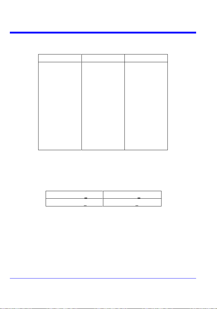
Vertical
Horizontal
Other
Maximum
Minimum
Peak-Peak
RMS
Cycle RMS
Mean
Cycle Mean
Top
Base
Top-Base
+Overshoot
-Overshoot
Tr 20-80%
Tf 80-20%
Tr 10-90%
Tf 90-10%
Frequency
Period
No. of +Pulses
No. of -Pulses
+Pulse Width
-Pulse Width
Duty Cycle
Integral
Skew
Skew@Level
100-240 Vrms (+10%)
50/60 Hz (+5%)
100-120 Vrms (+10%)
400 Hz (+5%)
Measure Tools
Standard Parameters:
General
Autocalibration: 3 minutes after power-up and whenever there is a change in ambient
temperature of 5 °C
Calibrator Signal: 0.6 V +/-1 %, 1 kHz +/-0.5 %
AC Power In:
Power Consumption: 75 VA (75 W) max.
Standby Power Consumption: 10 W max. (100 to 240 Vrms, 50/60 Hz)
Physical Dimensions (HxWxD): 190 mm (7.5”) x 285 mm (11.2”) x 102 mm (4.0”)
Weight: 3.2 kg (approx.)
Warranty and Service: 3-year warranty, calibration recommended yearly
Optional service programs include extended warranty and
20 WJ-A-GS-E Rev A
calibration services
Page 22

Getting Started Manual
CE
EN61326:1997 +A1:1998
+A2:2001 +A3:2003
EN61010-1:2001
UL
61010-1, 2nd edition
cUL
CAN/CSA C22.2 No 61010-1-04
Environmental: Temperature (operating): 10 to 35 °C
Temperature (storage): -20 to +60 °C
Humidity (operating): 5 to 80% RH (non-condensing)
Altitude (operating): up to 2000 m
Certifications:
WJ-A-GS-E Rev A 21
Page 23

WaveJet 300A Series
EC Declaration
of Conformity
Meets intent of the European Council Directives 73/23/EEC for product
safety and 89/336/EEC for electromagnetic compatibility. This declaration is
based upon compliance of the WaveJet oscilloscope to the following
standards:
EN 61326: 1997 +A1:1998 +A2:2001 +A3:2003 EMC requirements for
electrical equipment for measurement, control, and laboratory use.
Emissions:
EN 55011: 1998+A2:2002 Radiated & Conducted Emissions (Class A)
EN 61000-3-2:2000 Harmonic Current Emissions
Immunity:
EN 61000-4-2:1999 Electrostatic discharge
(±4 kV contact discharge; ±8 kV air discharge)
EN 61000-4-3: 2002+A1:2003 RF Radiated Fields
(3 V/m, 80 MHz to 1 GHz, 80% amplitude modulated)
EN 61000-4-4: 2004 Electrical Fast Transient/Burst
(1 kV on AC mains)
EN 61000-4-5: 1995+A1:2001 Surge
(1 kV differential mode, 2 kV common mode)
EN 61000-4-6: 1996+A1:2001 RF Conducted Field
(3 V, 150 kHz to 80 MHz, amplitude modulated with
1 kHz sine wave)
EN 61000-4-11: 2004 Mains Dips and Interruptions
(100% interruption for 1 full AC cycle)
EN 61010-1: 2001 Safety requirements for electrical equipment for
measurement control and laboratory use
With the following limits:
Installation (Overvoltage) Category II
(Line voltage in equipment and to wall outlet)
Installation (Overvoltage) Category I
(All mains isolated terminals)
Pollution Degree 2
Protection Class I
Declaration of Conformity:
22 WJ-A-GS-E Rev A
Page 24

Getting Started Manual
WJ-A-GS-E Rev A 23
Page 25

WaveJet 300A Series
Toxic or Hazardous Substances and Elements
Part Name
Lead
(Pb)
Mercury
(Hg)
Cadmium
(Cd)
Hexavalent
Chromium
(Cr6+)
Polybrominated
Biphenyls
(PBB)
Polybrominated
Diphenyl Ethers
(PBDE)
PCBAs X O X X X X
Mechanical Hardware
O O X O O
O
Sheet Metal
O O X O O
O
Plastic Parts
O O O O X
X
Cable Assemblies
X O X O X
X
Display X O X X X X
Power Supply
X X X O X
X
Fans X O X O X X
Battery for Processor
X O X O O
O
Power Cord
X O X O X
X
Ext Power Supply
(if present)
X X X O X
X
Probes (if present)
X O X O X
X
CD Drive (if present)
X O X O X
X
Fuse (if present)
X O X O O
O
Product Case (if
present)
O O O O X
X
Adapters/Modules (if
present)
X O O O O
O
Mouse (if present)
X O X O X
X
O: Indicates that this toxic or hazardous substance contained in all of the homogeneous materials for this part is below
the limit requirement specified in SJ/T11363-2006.
X: Indicates that this toxic or hazardous substance contained in at least one of the homogenous materials used for this
part is above the limit requirement specified in SJ/T11363-2006.
EFUP (Environmental Friendly Use Period) Use Conditions: refer to the environmental
conditions stated in the specifications section of this Manual.
EFUP for Battery: 5 Years
24 WJ-A-GS-E Rev A
Page 26
POWER-UP AND INSTALLATION
Press the power switch at bottom-left of the front of the scope to apply or
remove power.
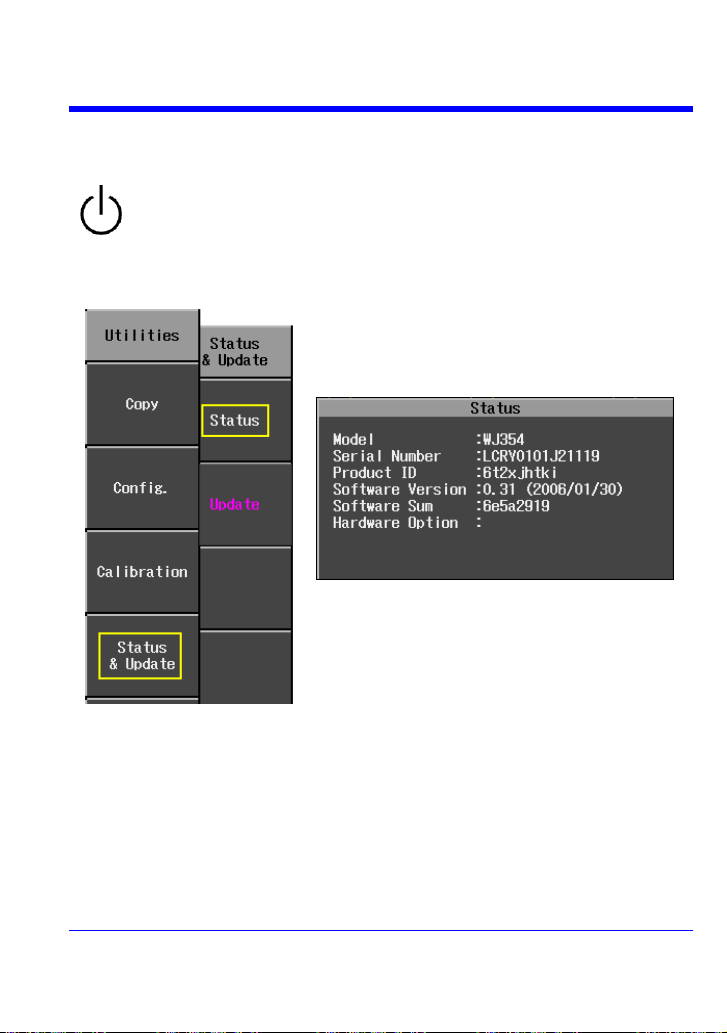
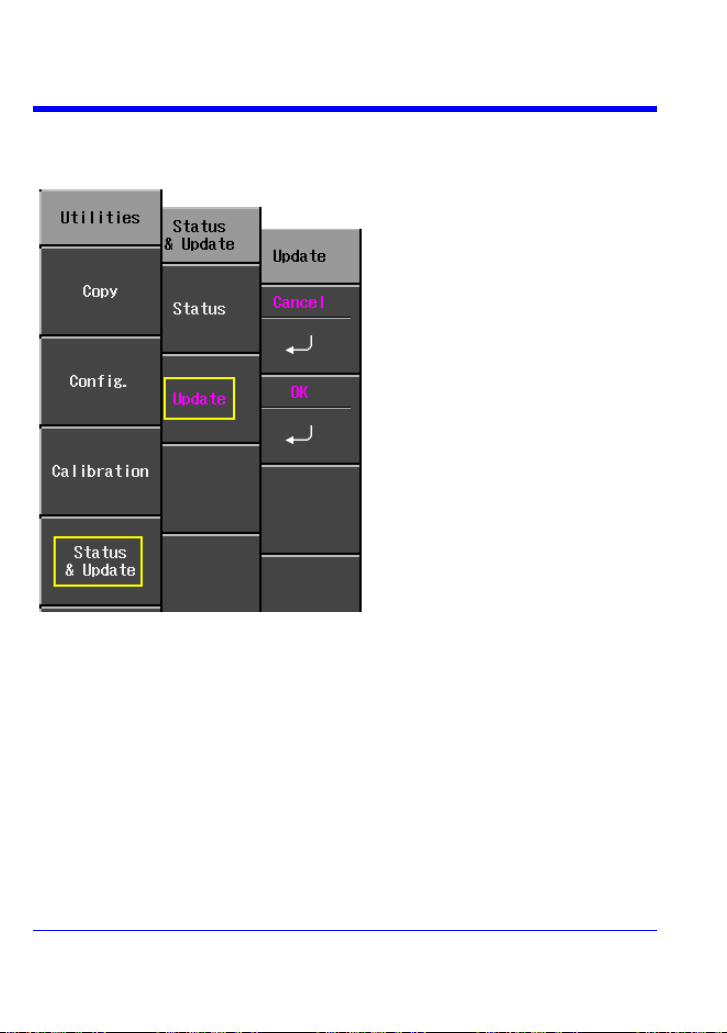
1. Press the front panel UTILITIES button.
2. From page 2/3 of the “Utilities” menu, select
Status & Update, then Status.
3. A pop-up box opens:
4. Press CLOSE to close the pop-up box.
Power-Up
Software
You can find out the scope's software and hardware configuration as follows:
Getting Started Manual
WJ-A-GS-E Rev A 25
Page 27
WaveJet 300A Series
1. Insert the USB memory device,
containing the software update file
in a root directory, into the USB
port at the front of the scope.
2. Press the front panel UTILITIES
button.
3. From page 2/3 of the “Utilities”
menu, select Status & Update,
then Update.
4. Select OK from the “Update”
menu; software download begins.
The Replay LED on the front panel
flashes while download is in
progress.
Updating the System Software
System software updates are downloaded through the USB memory port in the front of
the scope.
26 WJ-A-GS-E Rev A
Page 28

Getting Started Manual
PP006A
350 and 500 MHz
PP010
100 and 200 MHz
PROBES
LeCroy provides a passive probe for each WaveJet oscilloscope channel, as follows:
Probe Compensation
Passive probes must be compensated to flatten overshoot. This is accomplished by
means of a trimmer at the connector end of the probe.
1. Attach the connector end of your PP006A or PP010 probe to any channel.
2. Connect the probe end to the CAL output connector at the front of the scope.
3. Adjust the trim pot at the connector end of the probe until the square wave is
as flat as possible.
WJ-A-GS-E Rev A 27
Page 29
WaveJet 300A Series
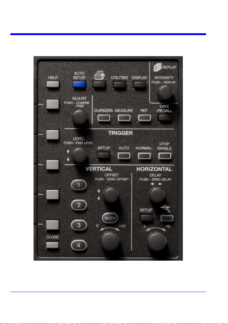
FRONT PANEL CONTROLS
Front Panel Buttons and Knobs
The control buttons of the WaveJet Series front panel are logically grouped into analog
and special function areas. The following table provides an explanation of the front
panel push buttons and knobs.
28 WJ-A-GS-E Rev A
Page 30
Getting Started Manual
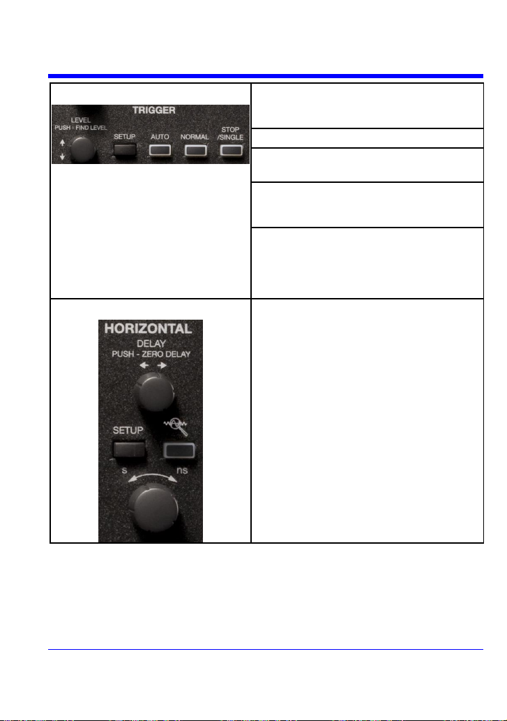
Trigger Controls
LEVEL -- Selects the trigger threshold level.
Press the LEVEL knob to have the scope find
the trigger level automatically.
SETUP -- Displays the trigger setup menu.
AUTO -- Triggers the scope after a time-out,
even if the trigger conditions are not met.
NORMAL -- Triggers the scope each time a
signal is present that meets the conditions set
for the type of trigger selected.
SINGLE/STOP -- Arms the scope to trigger
once (single-shot acquisition) when the input
signal meets the trigger conditions set for the
type of trigger selected. If the scope is already
armed, it will force a trigger.
Horizontal Controls
DELAY -- Horizontally positions the scope
trace on the display so you can observe the
signal prior to the trigger time. Press the
button to reset the delay to zero.
TIME/DIVISION -- Sets the time/division of the
scope timebase (acquisition system).
SETUP -- Displays the main horizontal setup
menu.
WJ-A-GS-E Rev A 29
Page 31
WaveJet 300A Series
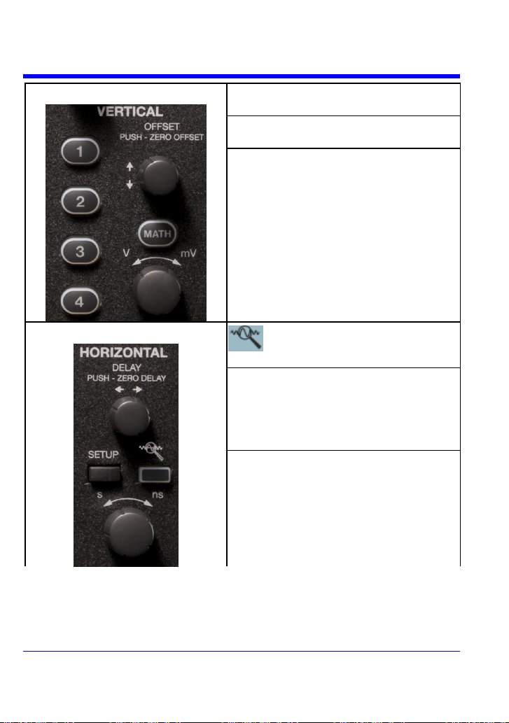
Vertical Controls
OFFSET -- Adjusts the vertical offset of each
channel individually.
VOLTS/DIV -- Adjusts the volts/division setting
(vertical gain) of the channel selected.
CHANNEL BUTTONS -- If the channel is already
ON, the channel button makes the channel
active.
If the channel is OFF, the channel button
turns the channel ON.
When the channel is active, the channel
button is lit, and the OFFSET and VOLTS/DIV
knobs are dedicated to that channel.
Zoom Control Knobs
QUICKZOOM -- Automatically displays
magnified views of up to four signal inputs.
Horizontal Delay -- In zoom mode, this knob
adjusts the horizontal position of a zoom trace
on the display. The zoom region is highlighted
on the source trace between vertical markers.
Unlike Delay, the position is not calibrated to
the trigger position.
Time/Division -- In zoom mode, this knob
adjusts the horizontal zoom (magnification
factor) of the selected zoom trace.
30 WJ-A-GS-E Rev A
Page 32

Special Features Controls
INTENSITY/REPLAY -- In intensity mode, use
this knob to adjust the brightness of your
waveforms. The intensity value is displayed at
the top of the screen at far right. Pressing the
button changes its function to Replay (history)
mode, which allows you to scroll backwards in
time to view past acquisitions. The number of
acquisitions stored depends on the Max
Memory Length setting. A count of the
waveforms is displayed at top-right of the
display.
In Spectrum (color-graded) persistence
mode, the INTENSITY knob is also used to
adjust the persistence saturation level.
ADJUST FINE/COARSE -- This dual-function
knob, when not used for cursor placement, is
used to dial values into data entry fields.
Press the knob to toggle between fine grain
(hundredths place) and coarse grain (tenths
place) adjustments. An icon located next to
the data entry field indicates the current
setting:
Fine Coarse
CURSORS -- This push button turns on the
cursors and displays the “Cursors” menu. If
you are in zoom mode, the cursors are placed
on the zoom traces. Press the CURSORS
button repeatedly to sequence through all
available cursor types.
When in cursors mode (CURSOR button is lit),
use the ADJUST knob to position the cursors.
If you open a different menu (Horizontal, for
example), the CURSOR button goes dark, and
the ADJUST knob can be used to set values in
another field.
MEASURE -- Displays a menu of measurement
parameters. The “Display Type” must be set
to YT mode.
Getting Started Manual
WJ-A-GS-E Rev A 31
Page 33

WaveJet 300A Series
REF -- Enables you to save up to five
waveforms in internal scope memory. You can
also recall waveforms.
SAVE/RECALL -- This button enables you to
save or recall scope setups and waveforms
from internal scope memory or from USB
memory. It is also used to recall a default
scope setup, which turns on all channels and
sets the vertical gain to 100 mV/div.
DISPLAY -- Allows you to set grid and
waveform display styles, and persistence.
MATH -- Displays a setup menu for math
functions.
General Control Buttons
HELP -- Displays context-sensitive on-line
Help. Press HELP then another front panel
button; information will be displayed about the
functioning of that button.
AUTO SETUP -- Automatically sets the scope's
horizontal timebase (acquisition system),
vertical gain and offset, as well as trigger
conditions, to display your signal.
UTILITIES -- This button displays a menu of
configurable scope features.
Print Screen -- Prints the displayed
screen to a USB memory device or connected
PictBridge® printer.
32 WJ-A-GS-E Rev A
Page 34

Getting Started Manual
CLOSE -- This button closes menus and pop-
up boxes. When menus are more than one
layer deep, it closes the top-most menu with
each successive press of the button.
WJ-A-GS-E Rev A 33
Page 35

WaveJet 300A Series
Trigger Delay -- This indicator is
located along the top edge of the
grid. Trigger delay allows you to see
the signal prior to the trigger time.
Trigger delay values are displayed
above the grid (-18.000 ns in this
example). Zero delay is the
horizontal center of the grid.
Post-Trigger delay is indicated by a
left-pointing arrow at the top of the
grid.
UNDERSTANDING DISPLAY INFORMATION
Grid Area
The grid area contains several indicators to help you understand triggering. Indicators
are coded to the channel colors (yellow here for channel 1).
34 WJ-A-GS-E Rev A
Page 36

Getting Started Manual
Trigger Level -- This indicator is
located at the right edge of the grid.
The value is displayed below the
grid.
Press the trigger level knob to reset
the level to 50%.
Zero Volts Level -- This indicator is
located at the left edge of the grid.
To change the zero volts level, turn
the vertical offset knob. Press the
knob to reset the indicator to the
middle of the grid.
Top Status Bar
This line displays acquisition and sampling information, and the setting of the intensity
control. When persistence is set to Spectrum mode, the intensity value represents
color saturation level.
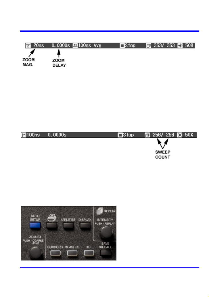
When zooming is enabled, this information also appears in the status bar:
The zoom magnification factor is the ratio of the timebase of the zoom trace to that of
the input waveform.
Zoom delay represents the portion of the input waveform being zoomed. As you turn
the Horizontal delay knob, this value becomes positive or negative depending on
whether the zoom is left (+) or right (-) of center.
The symbols M and Z indicate that the Main grid is on top and the Zoom grid is on the
bottom of the scope display.
WJ-A-GS-E Rev A 35
Page 37

WaveJet 300A Series
Bottom Status Bar
The status bar below the grid displays cursor (time and frequency) information and
additional trigger setup information.
Message Line
At the very bottom of the scope display is the message line. Prompts and error
messages are displayed on this line at far left. In addition, the following information is
displayed:
The clock mode can be either real time clock (RTC) or trigger time stamp (TRG).
Trace Descriptors
Channel and math trace descriptor labels are displayed below the grid.
36 WJ-A-GS-E Rev A
Page 38

TURNING ON TRACES
To turn on a channel trace, simply press the channel button.
This action also displays a setup menu for that channel. The
setup menu displayed (1/2 or 2/2) will be the one that was
displayed when the trace was last turned on.
To turn a trace off, press the button again. The setup menu,
however, will continue to be displayed until you press CLOSE
or open another menu.
Getting Started Manual
WJ-A-GS-E Rev A 37
Page 39

WaveJet 300A Series
To select an input coupling mode, turn on
the channel whose coupling you want to
change by pressing the appropriate
channel button. Select Coupling from
page 1/2 of the channel menu, then the
coupling mode from the next menu.
Reducing the bandwidth reduces the signal and system
noise, and prevents high frequency aliasing.
The choices of bandwidths are
Full
100 MHz
20 MHz
The WaveJet Series scope offers a wide variety of probe
attenuations:
1:1 1000:1
10:1 2000:1
100:1 Auto
VERTICAL SETTINGS AND CHANNEL CONTROLS
Choosing Coupling
Bandwidth Limiting
Probe Attenuation
38 WJ-A-GS-E Rev A
Page 40

Inverting Waveforms
Set this item to On to invert the waveform.
Activate the channel you want to adjust; there does not
need to be a signal applied. Turn the volts per division
knob in the VERTICAL group of controls.
The volts/div that you set is displayed in the top line of the
trace descriptor label.
This menu selection sets the grain of the volts/div knob.
Coarse sets the gain adjustment to 1-2-5 increments. Fine
sets the gain to as small as 2-mV increments.
The “Unit” menu offers a choice of Volts, Amperes,
Watts, Degrees C, or No Units.
Adjusting Sensitivity
Getting Started Manual
WJ-A-GS-E Rev A 39
Page 41

WaveJet 300A Series
Turn the vertical offset adjust knob in the VERTICAL group
of controls.
The offset value is displayed in the bottom line of the trace
descriptor label.
Adjusting the Waveform's Position
40 WJ-A-GS-E Rev A
Page 42
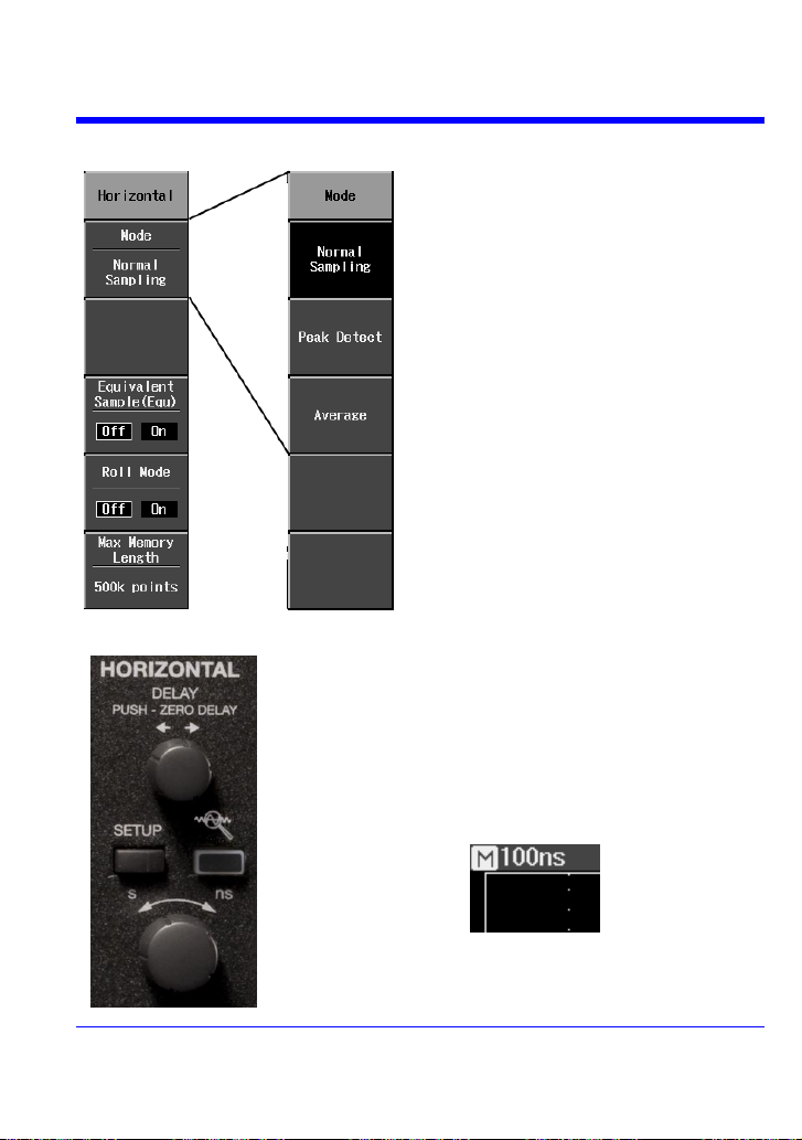
Getting Started Manual
Sampling modes are accessed by
pressing the SETUP button in the
HORIZONTAL control group.
There are three basic sampling modes:
Normal -- real-time mode
Peak Detect -- the maximum and
minimum values that occur in a zone
twice the sampling period are detected.
Average -- up to 256 waveforms
In addition, two other sampling modes are
available:
Equivalent Sampling Mode -- random
interleaved sampling (RIS) mode
Roll mode -- for slow acquisitions
You can change the timebase at any time without
displaying the “Horizontal” setup menu.
As you turn the time/div knob in the HORIZONTAL
control group, the value is displayed at the top-left of the
screen:
SAMPLING MODES
TIMEBASE SETUP
WJ-A-GS-E Rev A 41
Page 43
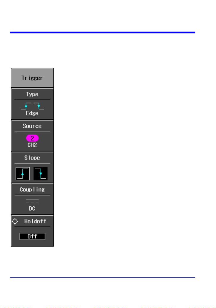
WaveJet 300A Series
Press the Type menu button to select Edge, Pulse Width,
Period, Pulse Count, or TV triggering.
Source lets you choose a channel input or an external input.
Use Slope to select a positive or negative edge for edge
triggering. This menu item becomes Polarity for the Pulse
Width trigger.
Coupling modes comprise AC, DC, HF Reject, and LF
Reject
Use the ADJUST knob to dial in a Holdoff value in units of
time.
TRIGGERING
Trigger Types
Trigger modes are accessed by pressing the SETUP button in the TRIGGER control
group of buttons and selecting Type from the “Trigger” menu:
42 WJ-A-GS-E Rev A
Page 44

Pulse Width Triggering
Source lets you choose a channel input or an external input.
Select positive or negative polarity.
Coupling modes comprise AC, DC, HF Reject, and LF
Reject
Select Pulse Width to set “less than” and “greater than”
criteria and range limits, and to set time values.
Getting Started Manual
WJ-A-GS-E Rev A 43
Page 45
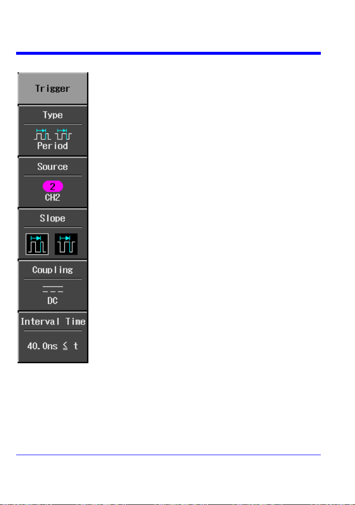
WaveJet 300A Series
Source lets you choose a channel input or an external input.
Select positive or negative polarity.
Coupling modes comprise AC, DC, HF Reject, and LF
Reject
Select Interval Time to set “less than” and “greater than”
criteria, and to set a time value.
Period Triggering
44 WJ-A-GS-E Rev A
Page 46
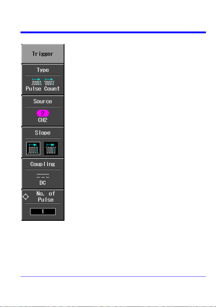
Pulse Count Triggering
Source lets you choose a channel input or an external input.
Select positive or negative polarity.
Coupling modes comprise AC, DC, HF Reject, and LF
Reject
Select No. of Pulse to set the number of pulses to count
before the scope triggers.
Getting Started Manual
WJ-A-GS-E Rev A 45
Page 47
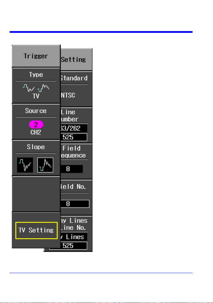
WaveJet 300A Series
Press the Type menu button to select a
standard: NTSC, PAL, or Custom.
Source lets you choose a channel input or
an external input.
Select Slope to set positive or negative
polarity.
Select TV Setting to set up the TV trigger.
TV Triggering
46 WJ-A-GS-E Rev A
Page 48

Horizontal Trigger Setup
Turn the DELAY knob in the HORIZONTAL control group to
adjust the trigger's horizontal position. The trigger location is
shown by a marker at the top of the grid and the time value is
given in the status bar above the grid:
Post-trigger delay is indicated by a left-pointing arrow at the
left edge of the grid.
Turn the LEVEL knob in
the TRIGGER control
group to adjust the
vertical threshold of the
trigger or the highlighted
trace. Level defines the
source voltage at which
the trigger will generate
an event: a change in the
input signal that satisfies
the trigger conditions.
Vertical
Getting Started Manual
WJ-A-GS-E Rev A 47
Page 49

WaveJet 300A Series
The trigger level is
indicated by a “T” to the
right of the grid. The
value is given below the
grid
A “T” with an underscore,
as shown here, indicates
a negative voltage level.
A “T” with a superscore
(overbar) indicates a
positive voltage level.
1. Press the front panel trigger SETUP
button.
2. Select Type from the “Trigger”
menu, then Edge.
3. Select a trigger source, positive or
negative slope, and trigger coupling
mode (AC. DC, HF Reject, or LF
Reject).
To Set Up an Edge Trigger
48 WJ-A-GS-E Rev A
Page 50

Getting Started Manual
4. If you want to set a holdoff time, use
the ADJUST knob to set a value. Push
the ADJUST knob to toggle between
fine and coarse adjustment.
To set a holdoff time of zero
seconds, turn the knob fully
counterclockwise until Off is
displayed in the “Holdoff” field.
WJ-A-GS-E Rev A 49
Page 51

WaveJet 300A Series
Time cursors are vertical lines that you move horizontally to
measure the difference in time or frequency values between
the cursors.
Amplitude cursors measure the difference in Y values between
the cursors.
You can display both time and amplitude measurements
together in this mode.
Gives the x value at a single point on your waveform.
WAVEFORM MEASUREMENTS
Measuring with Cursors
Cursors are important tools that aid you in measuring signal values. Cursors are
boundary markers that you can move across the grid. Use cursors to make fast,
accurate measurements and to eliminate guesswork.
Cursor Measurement Selections
Time values are displayed below the grid:
50 WJ-A-GS-E Rev A
Page 52

Getting Started Manual
Use the ADJUST knob to move cursors horizontally and
vertically.
The cursor selected for placement is indicated by a
highlighted fine grain icon in the menu and the cursor
itself has a higher brightness in the grid.
If Track is selected, both cursors move in unison and both
appear brighter in the grid.
Amplitude cursor values are displayed in the bottom line of the trace label for each
channel:
Note that the value depends on the time/div setting shown in the top line of each trace
label.
Cursor Placement
WJ-A-GS-E Rev A 51
Page 53
WaveJet 300A Series
PARAMETER MEASUREMENTS
Waveform analysis typically begins with the measurement of parameters. Parameter
measurement tools determine a wide range of waveform properties. Use them to
automatically calculate many attributes of your waveform, like rise time, rms voltage,
and peak-to-peak voltage, for example.
You can make common measurements on one or more waveforms. Parameter values
are displayed below the grid.
Measure Modes
Standard Vertical Parameters
Maximum -- Measures highest point in waveform. Unlike top, it does not
assume the waveform has two levels.
Minimum -- Measures the lowest point in a waveform. Unlike base, it does not
assume the waveform has two levels.
Peak-Peak -- Difference between highest and lowest points in the waveform.
RMS -- Root Mean Square of data between the cursors -- about the same as
sdev for a zero-mean waveform.
Cycle RMS -- Cyclic root mean square: Computes the square root of the sum of
squares of data values divided by number of points. Contrary to rms,
calculation is performed over an integer number of cycles, eliminating bias
caused by fractional intervals.
Mean -- Average of the data for a time domain waveform. Computed as
centroid of distribution for a histogram.
Cycle Mean -- Computes the average of the waveform data. Contrary to mean,
computes the average over an integer number of cycles, eliminating bias
caused by fractional intervals.
Top -- Higher of two most probable states, the lower being base; it is
characteristic of rectangular waveforms and represents the higher most
probable state determined from the statistical distribution of data point values in
the waveform.
Base -- Lower of two most probable states (higher is top). Measures lower level
in two-level signals. Differs from min in that noise, overshoot, undershoot, and
ringing do not affect measurement.
52 WJ-A-GS-E Rev A
Page 54

Getting Started Manual
Top-Base -- Measures the difference between upper and lower levels in two-
level signals. Differs from pkpk in that noise, overshoot, undershoot, and ringing
do not affect the measurement.
+Overshoot -- Amount of overshoot following a rising edge specified as
percentage of amplitude.
-Overshoot -- Amount of overshoot following a rising edge specified as
percentage of amplitude.
Standard Horizontal Parameters
Rise Time 10-90% -- Detects the first rise to pass through 50% of the amplitude
(top - base) of the waveform within the measurement section, and then
measures the time of transition from 10% to 90% at that rise.
Rise Time 20-80% -- Detects the first rise to pass through 50% of the amplitude
(top - base) of the waveform within the measurement section, and then
measures the time of transition from 20% to 80% at that rise.
Fall Time 80-20% -- Detects the first fall to pass through 50% of the amplitude
(top - base) of the waveform within the measurement section, and then
measures the time of transition from 80% to 20% at that fall.
Fall Time 90-10% -- Detects the first fall to pass through 50% of the amplitude
(top - base) of the waveform within the measurement section, and then
measures the time of transition from 90% to 10% at that fall.
Frequency -- Period of cyclic signal measured as time between every other pair
of 50% crossings. Starting with first transition after left cursor, the period is
measured for each transition pair. Values then averaged and reciprocal used to
give frequency.
Period -- Period of a cyclic signal measured as time between every other pair of
50% crossings. Starting with first transition after left cursor, period is measured
for each transition pair, with values averaged to give final result.
No. of +Pulses -- An integer number of positive pulses.
No. of -Pulses -- An integer number of negative pulses.
+Pulse Width -- Measures the time from the first rise until the first fall to pass
through 50% of the amplitude (top-base) of the waveform within the
measurement section.
-Pulse Width -- Measures the time from the first fall until the first rise to pass
through 50% of the amplitude (top-base) of the waveform within the
measurement section.
Duty Cycle -- Width as percentage of period.
WJ-A-GS-E Rev A 53
Page 55

WaveJet 300A Series
Other Parameters
Integral -- Computes area of waveform between cursors relative to zero level.
Values greater than zero contribute positively to the area; values less than zero
negatively.
Skew -- Measures from the 50% crossing of the first edge of a channel to the
50% crossing of a second channel.
Skew@Level -- Same as Skew, but with user-defined level.
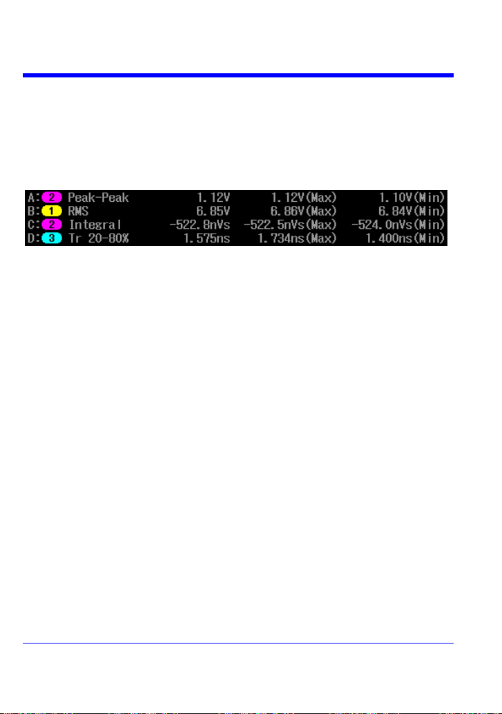
Statistics
For each parameter, you can display minimum and maximum values by pressing the
MEASURE button, then setting Min/Max to On.
54 WJ-A-GS-E Rev A
Page 56
Getting Started Manual
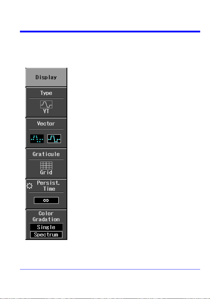
Display types comprise YT (voltage versus time), XY, and
XY Triggered.
Select points if you want to see actual sample points only.
Select lines if you want to see interpolated vectors
between points.
Besides a standard 8 x 10 matrix, you can elect to display
your waveforms on X and Y axes only (Axis), or on no grid
or axes (Frame).
Persistence decay times can be set to 0.1 s, 0.2 s, 0.5 s,
1 s, 2 s, 5 s, 10 s, or infinity. To clear persistence, press
either the V/div or time/div knobs.
In Single color gradation mode, all traces retain their
specific channel trace color. In Spectrum color gradation
mode, all traces are displayed at the same color saturation
level. The saturation level is set by the front panel intensity
knob.
DISPLAY FORMATS
Display Setup
The Display menu is accessed by pressing the DISPLAY button on the front panel.
WJ-A-GS-E Rev A 55
Page 57

WaveJet 300A Series
This is volts versus time, or dBm versus frequency for the
FFT function.
Asynchronous XY mode. Inputs must be connected to
channel 1 and channel 2. When this mode is selected Auto
is indicated as the trigger mode and the timebase control
cannot be adjusted:
Synchronous XY mode. Inputs must be connected to channel
1 and channel 2. Use this mode for periodic signals when
only a portion of the period is of interest. Set the timebase
and trigger level to acquire the desired portion.
To zoom waveforms, simply press the Zoom front panel
button. Zooms will be created in a second grid for all
displayed traces.
Use the time/div knob to adjust the zoom magnification factor.
Display Types
Zooming Waveforms
56 WJ-A-GS-E Rev A
Page 58
Getting Started Manual
To access Replay mode and scroll
through waveforms, press
STOP/SINGLE to stop acquisitions,
then press the INTENSITY/REPLAY
knob. The Replay LED lights to
confirm Replay Mode.
The zoom factor is displayed above the grid:
The zoom magnification factor is the ratio of the timebase of the zoom trace to that of
the input waveform.
Zoom delay represents the portion of the input waveform being zoomed. As you turn
the Horizontal delay knob, this value becomes positive or negative depending on
whether the zoom is left (+) or right (-) of center.
The symbols M and Z indicate that the Main grid is on top and the Zoom grid is on the
bottom of the scope display.
Replay Mode
Replay mode provides a way to scroll backwards in time to view past acquisitions.
The number of sweeps that can be stored depends on the Max Memory Length
selected in the “Horizontal” menu. Replay Mode does not function under the following
conditions:
in Roll Mode
in Average Mode
in Equivalent Sampling (RIS) mode
WJ-A-GS-E Rev A 57
Page 59
WaveJet 300A Series
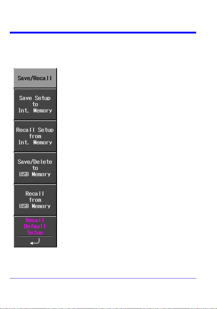
Five memory locations available. Setup files named with
current time and date.
Files are identified by time and date saved.
The Save function saves not only setup files but also
waveforms in various file formats: Binary, ASCII, Mathcad.
You can also save reference waveforms to USB memory.
Delete lets you erase all setup, waveform, and screen
image files from USB memory.
Recalls setups and waveform files from USB memory.
The default setup turns on all channels and sets the
following conditions with channel 1 as the trigger source:
Timebase = 200 ns/div Gain = 100 mV/div
Trigger mode = Auto Coupling = DC1Mohms
SAVE AND RECALL
Saving and Recalling Scope Settings
You can save scope settings to internal memory or USB memory. The “Save/Recall”
menu is accessed by pressing the SAVE/RECALL front panel button.
58 WJ-A-GS-E Rev A
Page 60
Getting Started Manual
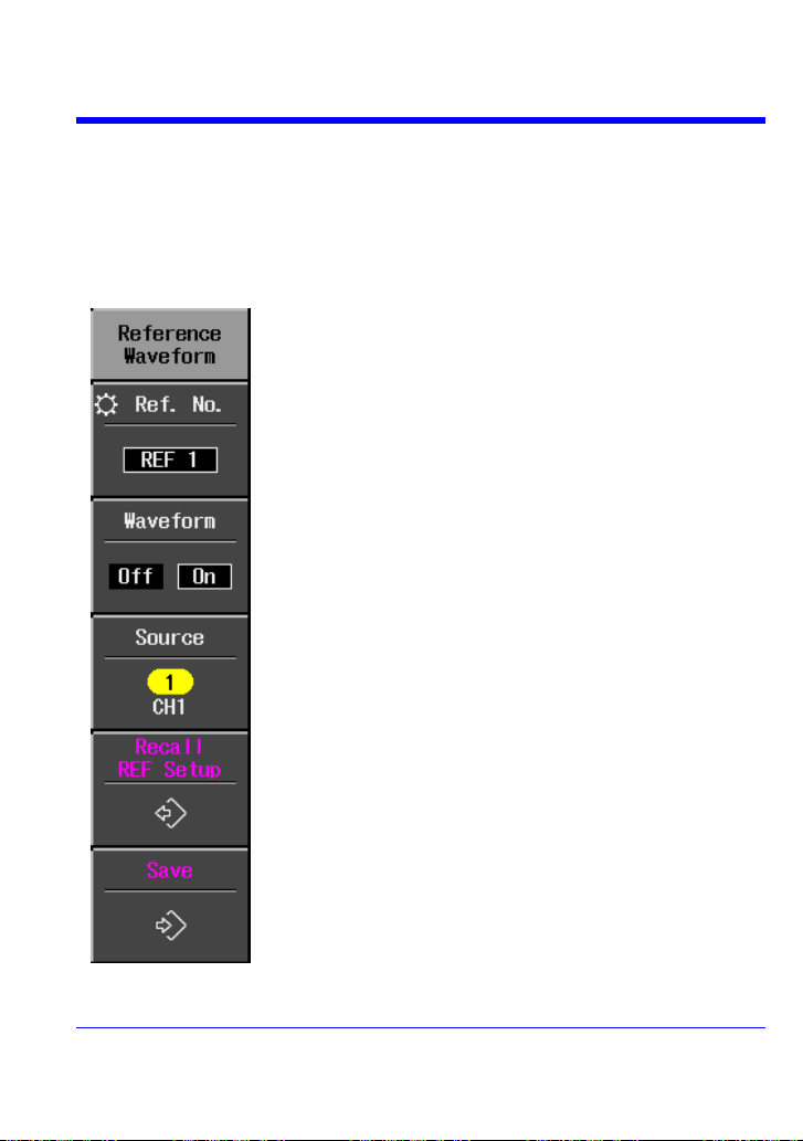
Select from five memory locations (REF 1 to REF 5). To
scroll through the choices, you can use the ADJUST knob or
press the Ref. No. button repeatedly.
Select On to display the reference waveform. All reference
waveforms appear white.
When saving a reference waveform, select the source.
When Recall REF Setup is selected, the setup stored in
the memory location selected above (REF 1 to REF 5) will
be recalled. This does not include setups saved in USB
memory, which are recalled through SAVE/RECALL.
When Save is selected, the source will be saved into the
memory location selected above (REF 1 to REF 5).
Saving and Recalling Waveforms
Reference waveforms can be saved in internal memory (five locations) or in USB
memory (limited by memory capacity of USB device). When you save a waveform, the
setup is saved also.
You can display up to five reference waveforms at the same time. Press REF to turn
them all off together. The “Reference Waveform” menu is accessed by pressing the
REF front panel button.
WJ-A-GS-E Rev A 59
Page 61
WaveJet 300A Series
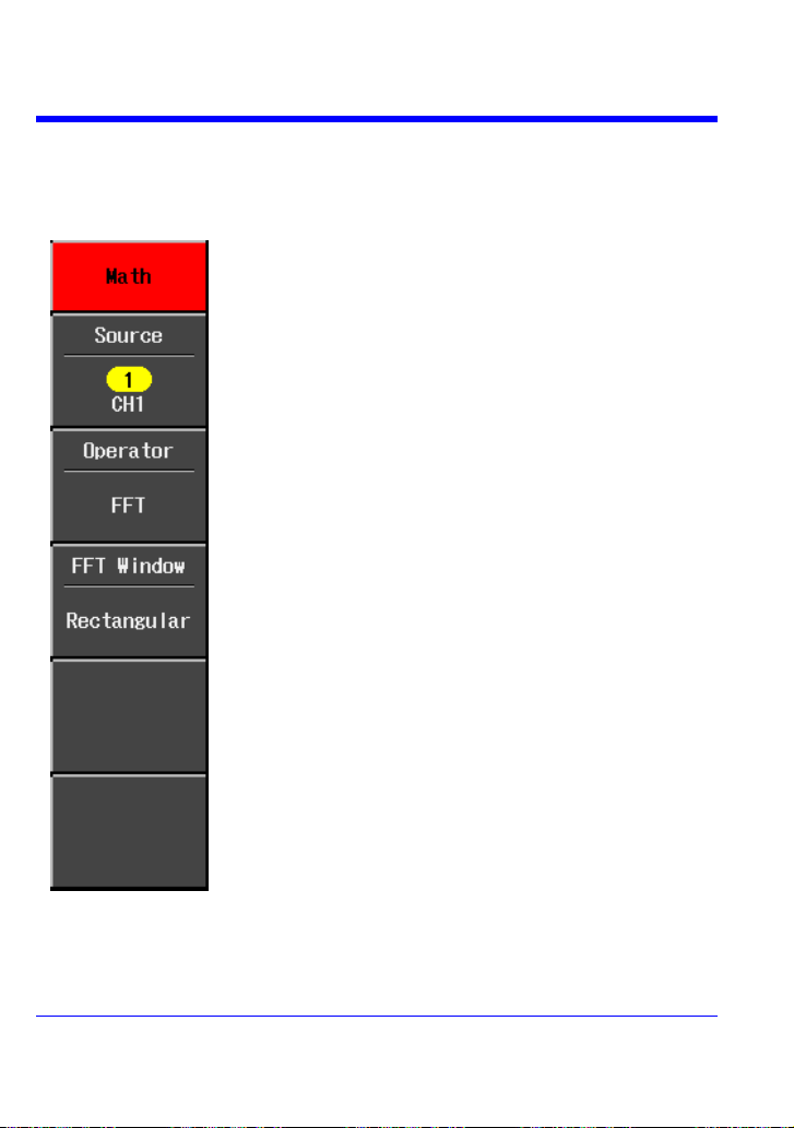
Source can be any channel, but not another math trace.
Select math operator +, -, x, or FFT.
If FFT is selected, select a window type:
Rectangular -- Normally used when the signal is transient
(completely contained in the time-domain window) or
known to have a fundamental frequency component that is
an integer multiple of the fundamental frequency of the
window.
VonHann -- Reduces leakage and improves amplitude
accuracy. However, frequency resolution is also reduced.
Flat Top -- Provides excellent amplitude accuracy with
moderate reduction of leakage, but with reduced frequency
resolution.
WAVEFORM MATH
Standard math functions comprise addition, subtraction, multiplication, and FFT. The
“Math” menu is accessed by pressing the MATH front panel button in the VERTICAL
control group.
60 WJ-A-GS-E Rev A
Page 62
UTILITIES
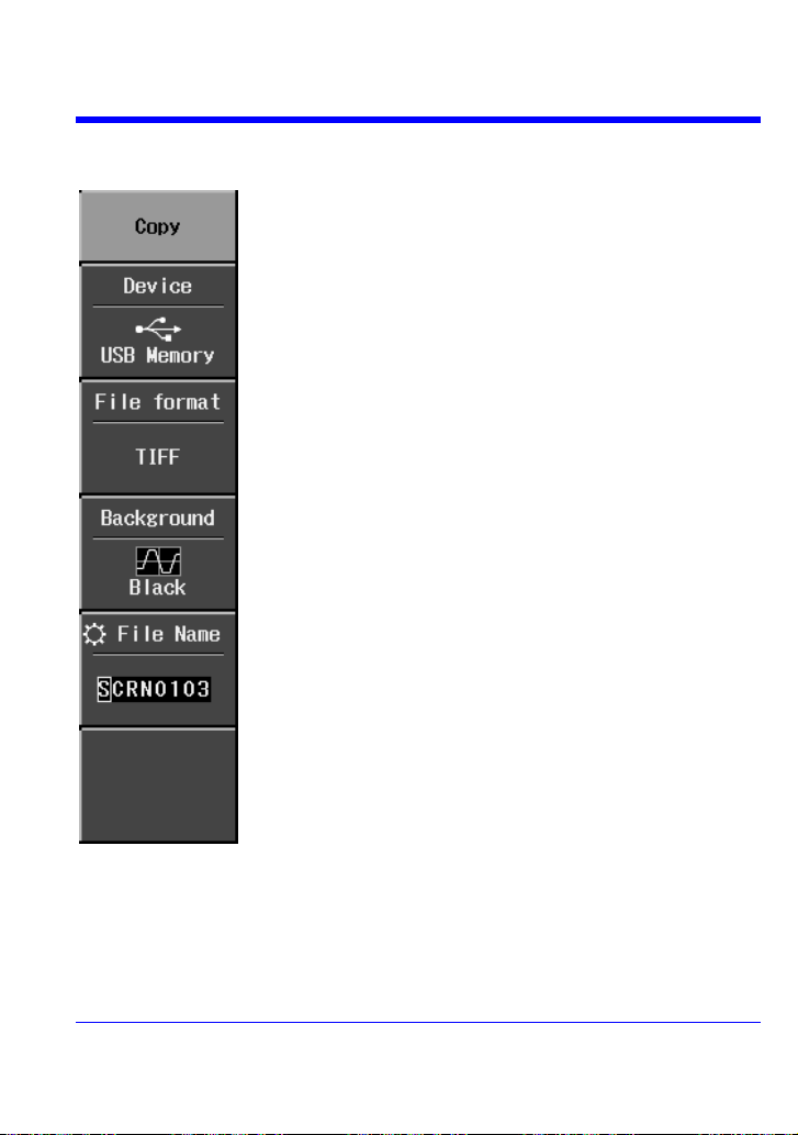
Device allows you to choose an output device, such as USB
or Printer. When Printer is selected the paper size and
background choices are available.
Selectable file formats are .tif, .bmp, and .png.
Background lets you select a black or white background for
the grid. Select White to save printer ink.
You have the option to name your files. Use the ADJUST knob
for this purpose. Rotate the knob to select a letter or number,
then push the knob to accept it.
Print Screen
Getting Started Manual
WJ-A-GS-E Rev A 61
Page 63
WaveJet 300A Series
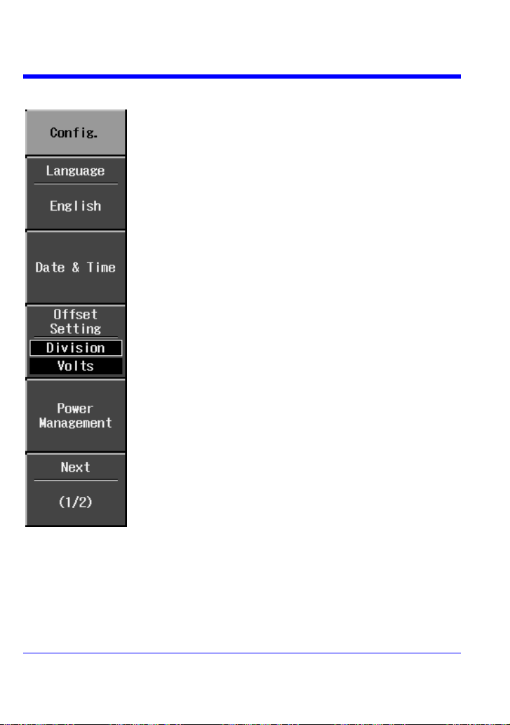
Language selects a UI local language. No reboot is required
to accept a change in language.
Select Date & Time to set the current time and to determine
the clock mode at the bottom of the screen: real time clock
(RTC) or trigger time stamp (TRG).
As you change the gain, Offset Setting allows you to either
keep the vertical offset level indicator stationary (Division) or
to have it move with the actual voltage level (Volts). When
Division is selected, the waveform will remain on the grid as
you increase the gain; whereas, if Volts is selected, the
waveform could move off the grid.
If desired, use Power Management to set the screen saver
timer (up to 15 minutes) and the power off timer (up to 60
minutes). These features can be set to Never also.
You can also set the backlight (screen) intensity (3 levels),
which is different from grid intensity (see menu 2/2).
Configuration -- Page 1/2
62 WJ-A-GS-E Rev A
Page 64

Configuration -- Page 2/2
Beep enabled gives audible confirmation of button presses
and knob rotations.
Panel Lock disables all front panel buttons and knobs until
unlock is selected from this menu, which remains
continuously displayed.
Use the front panel ADJUST knob to adjust the grid intensity
from 0 to 100%.
When Trigger Counter is On, the frequency of the trigger
source is measured and displayed in the message line at the
bottom of the screen:
Getting Started Manual
WJ-A-GS-E Rev A 63
Page 65
WaveJet 300A Series
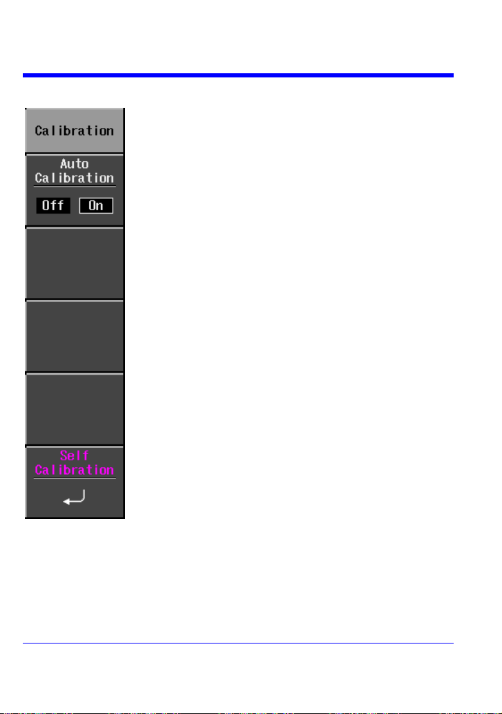
Calibrations can be set to occur automatically.
Autocalibration occurs three minutes after power-up and
whenever there is a change in ambient temperature of 5 °C.
Select Self Calibration to perform a manual calibration.
Calibration
64 WJ-A-GS-E Rev A
Page 66

Status & Update
The Status selection displays a pop-up box showing system
status, including serial number and software revision. Press
CLOSE to close the pop-up box.
Update is used to load firmware updates from USB memory.
Getting Started Manual
§ § §
WJ-A-GS-E Rev A 65
Page 67

Thank You for Purchasing
a WaveJet Oscilloscope.
 Loading...