

Page 1

Getting Started
Manual
LabMaster 9 Zi-A
Oscilloscopes
Page 2

LabMaster 9 Zi-A
Oscilloscopes
November, 2011
Page 3

LeCroy Corporation
700 Chestnut Ridge Road
Chestnut Ridge, NY, 10977-6499
Tel: (845) 578-6020, Fax: (845) 578 5985
Warranty
NOTE: THE WARRANTY BELOW REPLACES ALL OTHER WARRANTIES, EXPRESSED OR IMPLIED, INCLUDING BUT NOT LIMITED TO ANY IMPLIED
WARRANTY OF MERCHANTABILITY, FITNESS, OR ADEQUACY FOR ANY PARTICULAR PURPOSE OR USE. LECROY SHALL NOT BE LIABLE FOR ANY
SPECIAL, INCIDENTAL, OR CONSEQUENTIAL DAMAGES, WHETHER IN CONTRACT OR OTHERWISE. THE CUSTOMER IS RESPONSIBLE FOR THE
TRANSPORTATION AND INSURANCE CHARGES FOR THE RETURN OF PRODUCTS TO THE SERVICE FACILITY. LECROY WILL RETURN ALL PRODUCTS
UNDER WARRANTY WITH TRANSPORT PREPAID.
The oscilloscope is warranted for normal use and operation, within specifications, for a period of three years from shipment. LeCroy will either
repair or, at our option, replace any product returned to one of our authorized service centers within this period. However, in order to do this we
must first examine the product and find that it is defective due to workmanship or materials and not due to misuse, neglect, accident, or abnormal
conditions or operation.
LeCroy shall not be responsible for any defect, damage, or failure caused by any of the following: a) attempted repairs or installations by personnel
other than LeCroy representatives or b) improper connection to incompatible equipment, or c) for any damage or malfunction caused by the use of
non-LeCroy supplies. Furthermore, LeCroy shall not be obligated to service a product that has been modified or integrated where the modification
or integration increases the task duration or difficulty of servicing the oscilloscope. Spare and replacement parts, and repairs, all have a 90-day
warranty.
The oscilloscope's firmware has been thoroughly tested and is presumed to be functional. Nevertheless, it is supplied without warranty of any kind
covering detailed performance. Products not made by LeCroy are covered solely by the warranty of the original equipment manufacturer.
Internet: www.lecroy.com
© 2011 by LeCroy Corporation. All rights reserved.
Unauthorized duplication of LeCroy documentation materials other than for internal sales and distribution
purposes is strictly prohibited. However, clients are encouraged to distribute and duplicate LeCroy
documentation for their own internal educational purposes.
LeCroy and other product or brand names are trademarks or requested trademarks of their respective
holders. Information in this publication supersedes all earlier versions. Specifications are subject to change
without notice.
Manufactured under an ISO 9000
Registered Quality Management
System.
Visit www.lecroy.com to
view the certificate.
This electronic product is subject to disposal and recycling
regulations that vary by country and region. Many
countries prohibit the disposal of waste electronic
equipment in standard waste receptacles.
For more information about proper disposal and recycling
of your LeCroy product, please visit
www.lecroy.com/recycle.
LM9Zi-A-GSM-E RevA
919735-00 RevA
Page 4

Getting Started Manual
LM9Zi-A-GSM-E RevA
iv
TABLE OF CONTENTS
Welcome ................................................................... 13
Welcome ................................................................... 13
LabMaster 9 Zi-A Features ........................................ 13
Core Oscilloscope Functions ..................................... 13
Compatible Options and Accessories ....................... 13
Reference .................................................................. 13
Support ..................................................................... 14
Thank You ................................................................. 14
Safety Requirements ................................................ 14
Safety Symbols .......................................................... 14
Operating Environment ............................................ 16
Safety Certification ................................................... 17
Cooling ...................................................................... 18
AC Power Source....................................................... 19
Power Consumption ................................................. 19
Power and Ground Connections ............................... 19
Oscilloscope Calibration ........................................... 22
Cleaning .................................................................... 22
Abnormal Conditions ................................................ 22
Hardware and Connecting the LabMaster 9 Zi-A Modules24
LabMaster Hardware Overview ................................ 24
Master Control Module Configuration ..................... 24
Master Acquisition Module Configuration ............... 26
The Front of Your 9CZi-A Master Control Module .... 28
The Back of Your 9CZi-A Master Control Module ..... 29
The Front of Your CPU Module ................................. 32
The Back of Your CPU Module .................................. 35
Page 5

LabMaster 9 Zi-A Oscilloscopes
v
LM9Zi-A-GSM-E RevA
The I/O Panel ............................................................ 36
Removing and Attaching the Front Panel Control ... 41
Touch-Screen and External Displays ........................ 43
LeCroy External Display (Zi-EXTDISP-15) Setup ........ 43
LabMaster Configuration Setups................................. 46
Configuration Setups Overview ............................... 46
LabMaster Setup Styles ............................................ 46
Master Control Module Configuration Setup .......... 49
Connecting Your LabMaster Overview .................... 49
Power Cable Connections and Main Power Switch . 61
Master Acquisition Module Configuration Setup .... 64
Connecting Your LabMaster Overview .................... 64
Power Cable Connections and Main Power Switch . 78
Basic Controls ............................................................ 81
Hardware and Software Controls............................. 81
Front Panel Controls ................................................ 81
Front Panel Control Groupings ................................ 83
Front Panel Control Groupings Overview ................ 83
Trigger Front Panel Controls .................................... 84
Horizontal Front Panel Controls ............................... 85
Vertical Front Panel Controls ................................... 86
Zoom and Math Front Panel Controls ...................... 87
Probe and Signal Connection Interfaces ...................... 88
Probe and Signal Connection Interfaces Overview .. 88
Probe Interfaces ....................................................... 89
Probe Interfaces Overview ....................................... 89
ProBus Probe and Cable Connecting Interface ........ 91
ProLink Probe Interface ........................................... 92
Page 6

Getting Started Manual
LM9Zi-A-GSM-E RevA
vi
ProLink Interface Adapters ....................................... 93
Connecting the Adapters .......................................... 95
ProLink Probe Adapters ............................................ 95
Probes ....................................................................... 96
Passive Probe Compensation ................................... 97
Display Dashboard ..................................................... 98
Display Dashboard Overview .................................... 98
Screen Layout, Groupings, and Controls .................. 98
Menu Bar .................................................................. 98
The Quick Access Toolbar ......................................... 99
Quick Access Trigger Functions ................................ 99
Quick Access Processing Functions ......................... 100
Quick Access Undo Function ................................... 100
The Signal Display Grid ........................................... 101
Signal Display Grid Pop-Up Menu ........................... 103
Trace Descriptor Labels .......................................... 103
Actions for Trace Buttons ....................................... 105
Annotating Traces ................................................... 105
Dialog Area .............................................................. 107
Touch Screen Controls ............................................ 107
Actions for Trace Buttons ....................................... 113
Message Bar ............................................................ 114
Turning on Channels and Traces ................................ 115
Timebase .................................................................. 117
Timebase Overview ................................................ 117
Combining Channels ............................................... 117
Timebase Setup and Control .................................. 121
Sampling Modes ....................................................... 122
Page 7

LabMaster 9 Zi-A Oscilloscopes
vii
LM9Zi-A-GSM-E RevA
Sampling Modes Overview .................................... 122
Selecting a Sampling Mode .................................... 122
Single-shot Sampling Mode ................................... 122
Basic Capture Technique ........................................ 122
Sequence Display Modes ....................................... 125
Sequence Mode Setup ........................................... 126
Zooming Segments in Sequence Mode .................. 128
Displaying an Individual Segment .......................... 129
Viewing Time Stamps ............................................. 130
RIS Sampling Mode - For Higher Sampling Rates ... 130
Roll Mode ............................................................... 131
Vertical ..................................................................... 133
Vertical Overview ................................................... 133
Channel Controls .................................................... 133
Setting Up Channels ............................................... 135
Actions for Trace C1 Buttons.................................. 136
Pre-Processing Controls ......................................... 137
Response Optimization Modes .............................. 139
LabMaster 9 Zi-A Channel Setup ............................ 141
Setting up your channels ........................................ 141
Trigger ...................................................................... 147
Trigger Overview .................................................... 147
Trigger Types .......................................................... 148
Edge ........................................................................ 148
Width ...................................................................... 148
Pattern (Logic) ........................................................ 149
Smart ...................................................................... 149
Measurement ......................................................... 151
TV ........................................................................... 151
Page 8

Getting Started Manual
LM9Zi-A-GSM-E RevA
viii
MulitStage ............................................................... 151
Serial Trigger ........................................................... 152
Trigger Settings ....................................................... 153
Trigger Setup ........................................................... 154
Optimize for HF ....................................................... 157
Width Condition is .................................................. 158
Holdoff by Time or Events ...................................... 158
Auxiliary Input Trigger ............................................ 160
TriggerScan ............................................................. 161
Training TriggerScan ............................................... 162
Starting TriggerScan ................................................ 163
Saving TriggerScan Setups ...................................... 165
Viewing Waveforms .................................................. 166
Display ..................................................................... 166
Display Overview .................................................... 166
Display Setup .......................................................... 167
Moving Traces from Grid to Grid ............................ 170
Displays Containing Masks...................................... 170
Dual Display Grid Selection ..................................... 170
Persistence .............................................................. 171
Persistence Overview ............................................. 171
Persistence Setup ................................................... 172
WaveStream Display Mode .................................... 173
Adjusting Trace Intensity ........................................ 174
Zooming Waveforms ................................................. 175
Zooming Waveforms Overview .............................. 175
Previewing Zoomed Waveforms ............................. 176
Zooming a Single Channel ....................................... 176
Touch-and-Drag Zooming ....................................... 178
Page 9

LabMaster 9 Zi-A Oscilloscopes
ix
LM9Zi-A-GSM-E RevA
Turning Off Zoom ................................................... 179
Measuring with Cursors ............................................ 180
Measuring with Cursors Overview ......................... 180
Cursor Types ........................................................... 180
Cursors Setup ......................................................... 180
Quickly Displaying Cursors ..................................... 180
The Cursors Dialog ................................................. 181
Cursors on Math Functions .................................... 183
Measurement Parameters ......................................... 184
Measurement Parameters Overview ..................... 184
Turning On Parameters .......................................... 184
Quick Access to Parameter Setup Dialogs ............. 184
Parameter Setup .................................................... 185
Measure Modes ..................................................... 187
Standard Vertical Parameters ................................ 187
Standard Horizontal Parameters ............................ 187
Selecting Measure Modes ...................................... 187
Help Markers .......................................................... 188
Help Markers Setup ............................................... 189
Measurement Parameter Analysis ............................. 191
Measurement Parameter Analysis Overview ........ 191
Creating and Viewing a Histogram ......................... 193
Single Parameter Histogram Setup ........................ 193
Viewing Thumbnail Histograms (Histicons) ........... 197
Persistence Histogram ........................................... 198
Persistence Trace Range ........................................ 199
Persistence Sigma .................................................. 199
Creating and Viewing a Trend ................................ 199
Creating a Track View ............................................. 200
Page 10

Getting Started Manual
LM9Zi-A-GSM-E RevA
x
Pass-Fail Parameter Testing .................................... 201
Pass/Fail Parameter Testing Overview ................... 201
Testing and Enabling Pass/Fail Conditions ............. 202
Pass/Fail Setup on Qx Dialogs ................................. 203
The Actions Dialog .................................................. 208
Math ........................................................................ 211
Math Traces and Functions Overview .................... 211
Math Setup ............................................................. 212
Mask Testing ............................................................ 214
Creating a Mask ...................................................... 214
Quick Access to Pass/Fail Setup Dialogs ................. 216
Removing a Mask from the Display ........................ 216
Right-Hand Dialogs ................................................. 217
WaveScan Overview ................................................. 218
Signal Views ............................................................ 219
Search Modes ......................................................... 219
Parameter Measurements ...................................... 220
Sampling Mode ....................................................... 220
Customization Overview ........................................... 221
Documenting Your Work Using LabNotebook ............ 223
LabNotebook Overivew .......................................... 223
LabNotebook .......................................................... 224
Save/Recall ............................................................... 229
Save/Recall Overview ............................................. 229
Saving and Recalling Setups .................................... 230
Saving Oscilloscope Setup(s)................................... 230
Recalling Oscilloscope Setup(s) .............................. 230
Recalling Default Settings ....................................... 231
Page 11

LabMaster 9 Zi-A Oscilloscopes
xi
LM9Zi-A-GSM-E RevA
Saving and Recalling Waveforms ........................... 231
Saving Waveforms .................................................. 231
Recalling Waveforms.............................................. 235
Utilities ..................................................................... 237
Utilities Setup ......................................................... 237
Utilities Overview ................................................... 237
Utilities ................................................................... 237
Status...................................................................... 239
Remote Communication ........................................ 240
Printing and Hardcopy Functions ........................... 241
Aux Output ............................................................. 248
Date/Time .............................................................. 251
Options ................................................................... 252
Disk Utilities ........................................................... 252
Preferences ............................................................ 254
Preference Setup Overview ................................... 254
Preferences ............................................................ 254
Acquisition .............................................................. 255
E-Mail ..................................................................... 257
Color ....................................................................... 259
Miscellaneous ........................................................ 260
System Recovery Tool ............................................... 261
Restoring Software Using the Acronis Application 261
Restarting the Application ..................................... 264
Restarting the Operating System ........................... 265
Reference ................................................................. 266
Specifications ......................................................... 266
CERTIFICATIONS ..................................................... 266
CE Declaration of Conformity................................. 266
Page 12

Getting Started Manual
LM9Zi-A-GSM-E RevA
xii
EMC Directive ......................................................... 266
Low-Voltage Directive ............................................. 267
UL and cUL .............................................................. 268
Contact LeCroy for Support .................................... 268
China RoHS Compliance .......................................... 271
Windows® License Agreement ................................ 284
Index ........................................................................ 285
Page 13

LabMaster 9 Zi-A Oscilloscopes
13
LM9Zi-A-GSM-E RevA
Welcome
Welcome
Thank you for purchasing a LeCroy product. We're certain you'll be
pleased with the detailed features so unique to our instruments.
This LabMaster 9 Zi-A Series Online Help file may be accessed from your
oscilloscope with the intention of Operator's Manual usage. Sections can
be printed and the file itself can be saved to a USB memory device.
The information/content in this help file is arranged in the following
manner:
LabMaster 9 Zi-A Features
First, we cover the hardware and software features of your instrument in
the following sections:
Hardware and Connecting the LabMaster 9 Zi-A Modules
Basic Controls
Probe and Signal Connection Interfaces
Display Dashboard
Turning on Channels and Traces
Core Oscilloscope Functions
This section covers the core functions of LeCroy oscilloscopes.
Compatible Options and Accessories
Subsequent sections demonstrate the related Options and Accessories
available for your product.
Reference
The Reference section is set aside and covers items like Certifications (on
page 266) and how to Contact LeCroy for Support (on page 268). The
LeCroy website at www.lecroy.com always maintains the most current
specification information. The website should always be checked for
frequent updates.
Page 14

Getting Started Manual
LM9Zi-A-GSM-E RevA
14
Support
When your product is delivered, verify that all items on the packing list or
invoice copy have been shipped to you. Contact your nearest LeCroy
customer service center or national distributor if anything is missing or
damaged. If there is something missing or damaged, and you do not
contact us immediately, we cannot be responsible for replacement.
Thank You
We truly hope these materials provide increased comprehension when
using LeCroy's fine products.
Sincerely,
David C. Graef
LeCroy Corporation
Vice President and Chief Technology Officer
Safety Requirements
This section contains information and warnings that must be observed to
keep the instrument operating in a correct and safe condition. You are
required to follow generally accepted safety procedures in addition to
the safety precautions specified in this section.
Safety Symbols
Where the following symbols appear on the instrument's front or rear
panels, or in this manual, they alert you to important safety
considerations.
This symbol is used where caution is required. Refer to the accompanying
information or documents in order to protect against personal injury or
damage to the instrument.
Page 15

LabMaster 9 Zi-A Oscilloscopes
15
LM9Zi-A-GSM-E RevA
This symbol warns of a potential risk of shock hazard.
This symbol is used to denote the measurement ground connection.
This symbol is used to denote a safety ground connection.
On (Supply). This is the AC mains connect/disconnect switch at the back
of the instrument (if provided).
Off (Supply). This is the AC mains connect/disconnect switch at the back
of the instrument (if provided).
This symbol shows that the switch is a Standby (power) switch located on
the front of the oscilloscope. Pressing this button toggles the
oscilloscope's state between operating and Standby mode. This switch is
not a disconnect device. The instrument can only be placed in a complete
Power Off state by flipping the main power switch on the rear of the
instrument (if provided) to the off (Zero) position or by removing the
power cord. In cases where no main power switch is provided, removing
the main power cord is the disconnect device.
Page 16

Getting Started Manual
LM9Zi-A-GSM-E RevA
16
This symbol is used to denote Alternating Current.
CAUTION
The CAUTION sign indicates a potential hazard. It calls attention to a
procedure, practice or condition which, if not followed, could possibly
cause damage to equipment. If a CAUTION is indicated, do not proceed
until its conditions are fully understood and met.
WARNING
The WARNING sign indicates a potential hazard. It calls attention to a
procedure, practice or condition which, if not followed, could possibly
cause bodily injury or death. If a WARNING is indicated, do not proceed
until its conditions are fully understood and met.
CAT I
Installation (Overvoltage) Category rating per EN 61010-1 safety standard
and is applicable for the oscilloscope front panel measuring terminals.
CAT I rated terminals must only be connected to source circuits in which
measures are taken to limit transient voltages to an appropriately low
level.
Operating Environment
The instrument is intended for indoor use and should be operated in a
clean, dry environment. Before using this product, ensure that its
operating environment is maintained within these parameters:
Temperature: 5 to 40 °C.
Humidity: Maximum relative humidity 80 % for temperatures up to 31 °C
decreasing linearly to 50 % relative humidity at 40 °C (or at the upper
operational temperature limit).
Altitude: Up to 10,000 ft (3,048 m) at or below 25 °C.
Page 17

LabMaster 9 Zi-A Oscilloscopes
17
LM9Zi-A-GSM-E RevA
Note: Direct sunlight, radiators, and other heat sources should be taken
into account when assessing the ambient temperature.
WARNING
The oscilloscope must not be operated in explosive, dusty, or wet
atmospheres.
CAUTION
Protect the oscilloscope's display touch screen from excessive impacts
with foreign objects.
CAUTION
Do not exceed the maximum specified front panel terminal voltage
ratings. Refer to Specifications for more details. The specifications for
maximum allowable voltages are located on a label on the front of the
oscilloscope.
Safety Certification
The design of the instrument has been verified to conform to applicable
EN 61010-1, UL 61010-1 2nd Edition and CSA C22·2 No·61010-1-04 safety
standards for the following limits:
Installation (Overvoltage) Categories II (Mains Supply Connector)
& I (Measuring Terminals).
Pollution Degree 2.
Protection Class I.
PLEASE NOTE THE FOLLOWING:
Installation (Overvoltage) Category II refers to local distribution
level, which is applicable to equipment connected to the mains
supply (AC power source).
Page 18

Getting Started Manual
LM9Zi-A-GSM-E RevA
18
Installation (Overvoltage) Category I refers to signal level, which is
applicable to equipment measuring terminals that are connected
to source circuits in which measures are taken to limit transient
voltages to an appropriately low level.
Pollution Degree 2 refers to an operating environment where
normally only dry non-conductive pollution occurs. Conductivity
caused by temporary condensation should be expected.
Protection Class 1 refers to grounded equipment, in which
protection against electric shock is achieved by Basic Insulation
and by means of a connection to the protective ground conductor
in the building wiring.
Cooling
The instrument relies on forced air cooling with internal fans and
ventilation openings. Care must be taken to avoid restricting the airflow
around the apertures (fan holes) on any side of the oscilloscope. For
sides and rear apertures, ensure adequate ventilation by leaving the
required 10 cm (4 inch) minimum gap around the sides and rear of the
instrument. For bottom apertures, the oscilloscope feet (up or down)
provide adequate clearance. Ensure at least the minimum feet clearance
is achieved as paper or light objects can be drawn to and obstruct the
opening(s).
CAUTION
Do not block oscilloscope ventilation holes. For models with bottom
apertures, always keep items like sheets of paper clear of the
oscilloscope bottom.
The instrument also has internal fan control circuitry that regulates the
fan speed based on the ambient temperature. This is performed
automatically after start-up with no manual intervention required.
CAUTION
Do not allow any foreign matter to enter the oscilloscope through the
ventilation holes, etc.
Page 19

LabMaster 9 Zi-A Oscilloscopes
19
LM9Zi-A-GSM-E RevA
AC Power Source
100 to 240 VAC (+/-10%) at 50/60 Hz (+/- 10%).
No manual voltage selection is required because the instrument
automatically adapts to line voltage.
Power Consumption
Master Acquisition Module - LabMaster 9xxMZi-A
13-20 GHz Models - </= 850 watts (850 VA) for 13-20 GHz
LabMaster 9xxMZi-A series models (depending on accessories
installed - probes, PC port plug-ins, etc.).
30-45 GHz Models - </= 900 watts (900 VA) for 30-45 GHz
LabMaster 9xxMZi-A series DBI models (depending on accessories
installed - probes, PC port plug-ins, etc.).
Master Control Module - LabMaster 9CZi-A
</= 450 watts (450 VA)
Slave Acquisition Module - LabMaster 9xxSZi-A
13-20 GHz Models - </= 700 watts (700 VA) for 13-20 GHz
LabMaster 9xx SZi-A series models (depending on accessories
installed - probes, PC port plug-ins, etc.).
30-45 GHz Models - </= 750 watts (750 VA) for 30-45 GHz
LabMaster 9xx SZi-A series DBI models (depending on accessories
installed - probes, PC port plug-ins, etc.).
CPU Module - Included with LabMaster 9xxMZi-A
</= 400 watts (400 VA)
Power and Ground Connections
The Master Acquisition Module - LabMaster 9xxMZi-A is provided with a
15A/250V 14AWG rated grounded cord set containing a molded threeterminal polarized plug and a specific IEC-60320 (Type C15) connector for
making line voltage and safety ground connections.
The Master Control Module - LabMaster 9CZi-A, Slave Acquisition
Module - LabMaster 9xxSZi-A, and the CPU Module is each provided
with a standard 10A/250V 18AWG rated grounded cord set with an
IEC320 right-angle Type C13 connector.
Page 20

Getting Started Manual
LM9Zi-A-GSM-E RevA
20
On either cord set/plug, the AC inlet ground terminal is connected
directly to the frame of the instrument. For adequate protection against
electrical shock hazard, the power cord plug must be inserted into a
mating AC outlet containing a safety ground contact.
WARNING - Electrical Shock Hazard
Only use the power cord provided with your instrument.
Any interruption of the protective conductor inside or outside of the
oscilloscope, or disconnection of the safety ground terminal creates a
hazardous situation. Intentional interruption is prohibited.
In Standby mode, the oscilloscope is still connected to the AC supply. The
instrument can only be placed in a complete Power Off state by flipping
the main power switch on the rear of the instrument (if provided) to the
off (Zero) position or by removing the power cord. In cases where no
main power switch is provided, removing the main power cord is the
disconnect device.
CAUTION
Always use the Power Switch or File → Shutdown command in the
software to properly shut down your instrument. Never substitute this
practice by pulling the instrument power cord from the socket or
shutting down a connected power strip.
CAUTION
The outer conductors of the front panel BNC or ProBus terminals for all
input channels are connected to the instrument's chassis and therefore
to the safety ground.
Page 21

LabMaster 9 Zi-A Oscilloscopes
21
LM9Zi-A-GSM-E RevA
Standby (Power) Switch and Oscilloscope Operational
States
With regard to the Master Control Module - LabMaster 9CZi-A and the
CPU Module , the Standby (Power) switch controls the operational state
of the oscilloscope. This toggle switch is activated by momentarily
pressing and releasing it.
Also on certain models, the color of the LED below the switch indicates
the status of the oscilloscope as follows:
On (LED Green)* – oscilloscope is fully powered and operational
Standby (LED off)* – oscilloscope is powered off (except for some
housekeeping circuits)
Standby (LED Blinks Green) – oscilloscope's computer subsystems
(hard drive, etc.) are in Standby (reduced Power mode). All other
oscilloscope subsystems are fully powered.
* Factory Settings
The oscilloscope's factory settings result in only two basic oscilloscope
states: On or Standby. In the case of Standby, the oscilloscope is powered
off with the exception of some housekeeping circuitry. The oscilloscope
can only be placed in a complete power off state by flipping its main
power switch to the Off (zero) position, or by unplugging the
instrument's power cord from the primary power source (AC outlet). It is
recommended that the power cord be unplugged from the AC outlet if
the oscilloscope is not being used for an extended period of time.
Changes can be made to the oscilloscope's original factory settings via
the Power Options Properties menu in Windows under Control Panel →
Power Options. A Windows Power Option named Standby provided
control of only the oscilloscope's computer subsystems (CPU, hard drive,
etc.) and did not affect the other subsystems within the oscilloscope. In
general, these other subsystems remain fully powered. For additional
information on setting these Power Options, see the Windows Help
menu or other related technical documentation. In terms of control
buttons, this oscilloscope uses only a power button/switch and therefore
references to a sleep button are not applicable.
Page 22

Getting Started Manual
LM9Zi-A-GSM-E RevA
22
The oscilloscope can always be placed in the Standby state (LED Off) –
Power Off (except for some housekeeping circuits) by pressing and
holding in the Standby toggle switch for approximately 5 seconds.
CAUTION
Hibernate mode is not supported by the Power button. Therefore,
Windows® Power Options must not be changed from the default Never
setting to System Standby or System Hibernate modes.
CAUTION
Always use the Power Switch or File → Shutdown command in the
software to properly shut down your instrument. Never substitute this
practice by pulling the instrument power cord from the socket or
shutting down a connected power strip.
Oscilloscope Calibration
The recommended calibration interval is one year. Calibration should be
performed by qualified personnel only.
Cleaning
Clean only the exterior of the instrument, using a damp, soft cloth. Do
not use chemicals or abrasive elements. Under no circumstances allow
moisture to penetrate the instrument.
Avoid electrical shock hazard by unplugging the power cord from the AC
outlet before cleaning.
WARNING - Electrical Shock Hazard
No operator serviceable parts inside.
Do not remove covers.
Refer servicing to qualified personnel.
Abnormal Conditions
Operate the instrument only as intended by the manufacturer.
Page 23
LabMaster 9 Zi-A Oscilloscopes
23
LM9Zi-A-GSM-E RevA
If you suspect the oscilloscope's protection has been impaired,
disconnect the power cord and secure the instrument against any
unintended operation.
The oscilloscope's protection is likely to be impaired if, for example, the
instrument shows visible damage or has been subjected to severe
transport stresses.
Proper use of the instrument depends on careful reading of all
instructions and labels.
WARNING
Any use of the oscilloscope in a manner not specified by the
manufacturer may impair the instrument's safety protection.
Page 24

Getting Started Manual
LM9Zi-A-GSM-E RevA
24
Hardware and Connecting the
LabMaster 9 Zi-A Modules
LabMaster Hardware Overview
LabMaster is a unique modular oscilloscope solution that allows a
configuration of more channels at higher bandwidths than traditional
four channel oscilloscopes. It is ideally suited for test situations where
there are many lanes of serial data to be captured and analyzed
simultaneously, crosstalk analysis or for capturing four channels at the
highest-possible bandwidths for optical coherent modulation
applications. Each LabMaster consists of a single Master Acquisition
Module or Master Control Module, and optional additional Slave
Acquisition Modules. Slaves can be added at any time for easy channel
upgrades. Bandwidth upgrades are available for both Master Acquisition
Modules and Slave Acquisition Modules for future scalability.
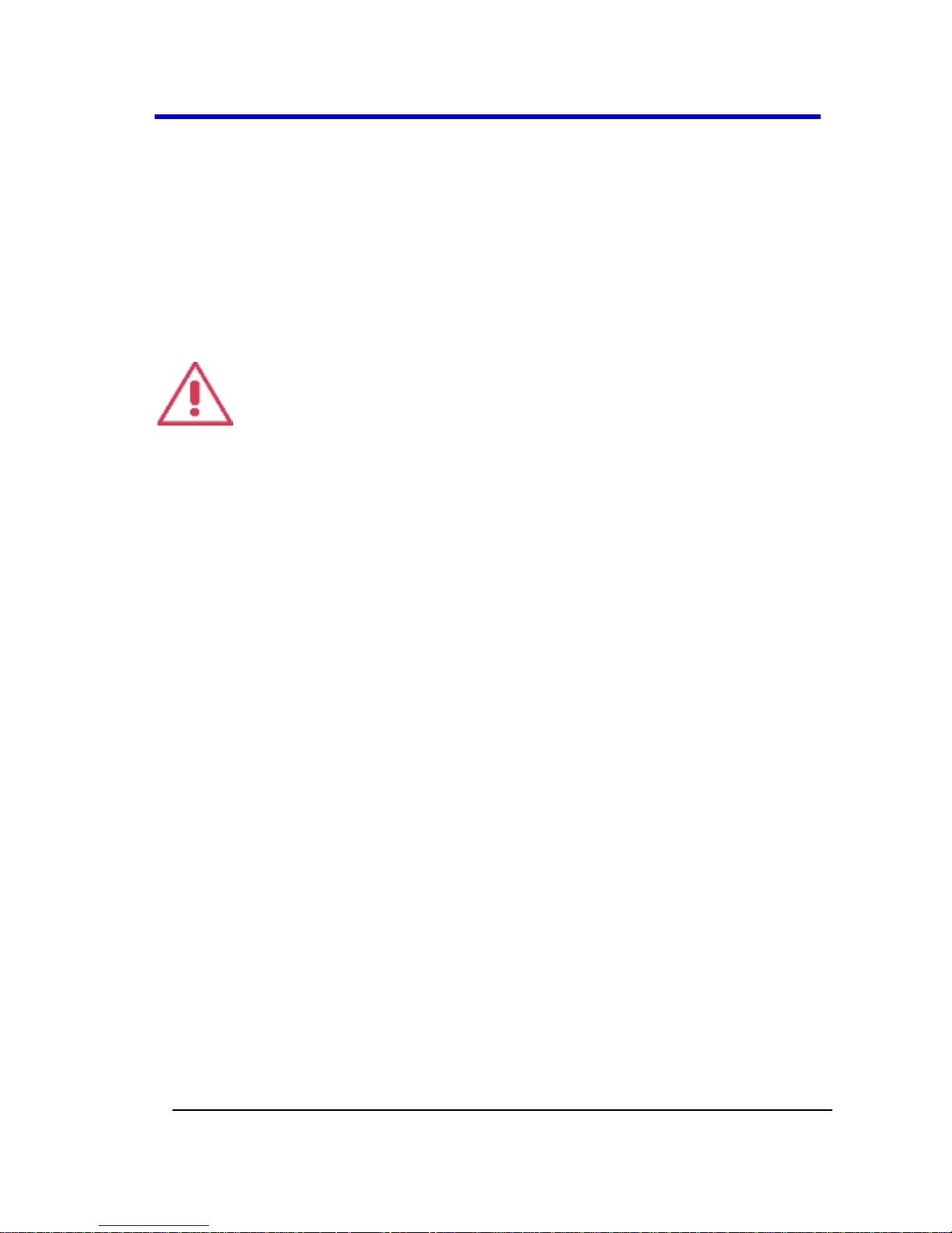
Unique ChannelSync™ architecture ensures precise synchronization
between all oscilloscope channels located in different acquisition
modules. A single 10 GHz distributed clock signal is generated in the
Master Acquisition Module or Master Control Module, and then used in
or distributed to as many as five Master Acquisition Modules or Slave
Acquisition Modules. The 10 GHz clock frequency - 1000 times faster
than the 10 MHz reference clocks commonly used to synchronize lab
equipment - ensures precise synchronization and high-timebase accuracy
between all acquisition modules. The system ensures Slave Acquisition
Modules are automatically identified to the Master, and software
calibration routines allow for fast calibration and correction for any static
acquisition skew between all acquisition modules.
Note: Detailed steps explaining how to setup either configuration are
covered in Configuration Setups Overview (on page 46).
Master Control Module Configuration
A LabMaster configuration using a Master Control Module includes a
9CZi-A Master Control Module with up to five Slave Acquisition
Modules.
Page 25
LabMaster 9 Zi-A Oscilloscopes
25
LM9Zi-A-GSM-E RevA
Note: If your LabMaster system runs multiple Slave Acquisition
Modules, for optimal channel access and convenience, LeCroy
recommends stacking the modules on top of each other on your bench,
inside LeCroy's available Tower or inside of your own rack (modules
must be specifically ordered for rack mounting from the LeCroy
factory).
9CZi-A Master Control Module with up to five 9xxSZi-A Slave Acquisition
Modules
Page 26

Getting Started Manual
LM9Zi-A-GSM-E RevA
26
Master Acquisition Module Configuration
A LabMaster configuration using a Master Acquisition Module includes a
9xxMZi-A Master Acquisition Module with corresponding CPU Module,
and up to four 9xxSZi-A Slave Acquisition Modules.
9xxMZi-A Master Acquisition Module with corresponding CPU Module, and up
to four 9xxSZi-A Slave Acquisition Modules
Page 27

LabMaster 9 Zi-A Oscilloscopes
27
LM9Zi-A-GSM-E RevA
Note: The 9xxSZi-A Slave Acquisition Modules are available in a variety
of bandwidths and channel density configurations. Each example
shown previously contains a mix of 20 GHz and >20 GHz Slave
Acquisition Modules. Each Slave Acquisition Module is compatible
with either Master Module (Control or Acquisition). Refer to
specifications on the datasheet maintained at www.lecroy.com and
contact your LeCroy representative for details using Contact LeCroy for
Support (on page 268) for more information.
Page 28

Getting Started Manual
LM9Zi-A-GSM-E RevA
28
The Front of Your 9CZi-A Master Control Module
The 9CZi-A Master Control Module includes Controls, Display, CPU, and
ChannelSync Clock Architecture. All acquisition capability is contained in
separate Slave Acquisition Modules.
This topic shows the front of your 9CZi-A Master Control Module.
Numbered labels on this image correspond with descriptions on the
following table.
Number and Description
1. Power
Button
2. Fast Edge
Output
3. USB Ports
4. Detachable Front
Panel Control
5. Front Panel
Control Release
Switch
Page 29

LabMaster 9 Zi-A Oscilloscopes
29
LM9Zi-A-GSM-E RevA
The Back of Your 9CZi-A Master Control Module
Numbered labels on this image of the 9CZi-A Master Control Module
correspond with descriptions on the following table.
Number and Description
1. Channel Sync
Outputs - SMA 10
GHz Clock and
PCIe 1 Lane
Control
Connections (for
corresponding
Slave Acquisition
Modules)
2. AC Power Plug
3. The I/O Panel (on
page 36)
4. DVI-D Video
Input
5. Removable
Hard Drive
6. PCIe 4 Lane
Data Inputs
(from
corresponding
Slave
Acquisition
Modules).
7. 10 MHz
Reference
Clock Input
(Grounded EMI
Shield required
when port is
not in use)
8. DVI-D Video
Input (from
DVI-D Video
Output, item
number 4)
9. 10 MHz
Reference
Clock Output
Page 30

Getting Started Manual
LM9Zi-A-GSM-E RevA
30
PLEASE NOTE THE FOLLOWING:
Cap-off unused ChannelSync SMA sockets (item number 1 on the
back of your Master Control Module, shown previously) using the
provided chain-linked 50 Ω terminations (not shown).
DVI-D Video Output and Input connectors, item numbers 5 and 6,
respectively in The I/O Panel (on page 36), must be connected
with the supplied 1 meter cable for your touch-screen display to
function.
The locations used for the PCIe 4 Lane Data Inputs (item number
6, shown previously) also accommodate available PCIe Expansion
Slot options for GPIB, LSIB, and support for LeCroy External
Display (Zi-EXTDISP-15). However, option cards must be specified
when ordering and installed at the LeCroy factory into any number
of the same five slots used for the Slave Acquisition Modules. The
slot between the DVI-D Video Output connector and the PCIe 4
Lane Data Connection for Channels 1-4 is unavailable.
The AUX IN connection for 50 Ω input only is provided on The
Back of Your 9CZi-A Master Control Module.
10 MHz Reference Clock Inputs are specifically intended for
synchronization with other instruments; not between Master and
Slave modules.
Contact your LeCroy representative for details using Contact
LeCroy for Support (on page 268).
Contact a system administrator when connecting to any internal
LAN.
The Front of Your 9xxMZi-A Master Acquisition
Module
The 9xxMZi-A Master Acquisition Module includes Controls, Display,
ChannelSync Clock Architecture, and a single, internal acquisition
system. The CPU is contained in the separate, physical CPU Module, but
is included with the LabMaster 9xxMZi-A. Additional acquisition
capability is contained in separate Slave Acquisition Modules.
Page 31

LabMaster 9 Zi-A Oscilloscopes
31
LM9Zi-A-GSM-E RevA
This topic shows the front of your 9xxMZi-A Master Acquisition Module.
Numbered labels on this image correspond with descriptions on the
following table.
Number and Description
1. Power Button
2. Channel Row
LED Indicator
3. Channel Inputs
4. Auxiliary Input
and Output
5. Volume Control
and Mute
Button
6. Ground
Connector
7. Speaker
8. Fast Edge,
Recovered
Clock, and Data
Outputs
9. USB Ports
10. Detachable Front
Panel Control
11. Front Panel
Control Release
Switch
Page 32

Getting Started Manual
LM9Zi-A-GSM-E RevA
32
The Front of Your CPU Module
The Master Acquisition Module configuration, has the 9xxMZi-A Master
Acquisition Module connecting to a separate CPU Module. The rest of
the topic shows the front of this CPU Module.
Page 33

LabMaster 9 Zi-A Oscilloscopes
33
LM9Zi-A-GSM-E RevA
The Back of Your 9xxMZi-A Master Acquisition
Module
Numbered labels on this image of the 9xxMZi-A Master Acquisition
Module correspond with descriptions on the following table.
Number and Description
1. Channel Sync
Outputs - SMA 10
GHz Clock and PCIe 1
Lane Control
Connections (for
corresponding Slave
Acquisition Modules)
2. Power Switch
3. AC Power Plug
4. PCIe 1 Lane
DATA
Output (to
CPU
Module)
5. DVI-D Video
Input (for
DVI-D
Output
Signal from
CPU)
6. 10 MHz
Reference
Clock Input
(Grounded EMI
Shield required
when port is
not in use)
7. LBUS Output
8. 10 MHz
Reference
Clock Output
Page 34

Getting Started Manual
LM9Zi-A-GSM-E RevA
34
PLEASE NOTE THE FOLLOWING:
Cap off unused ChannelSync SMA sockets (1 on the screen-shot
shown previously) using the provided chain-linked 50 Ω
terminations.
VGA/WXGA Video Input connectors (item number 5 on the
screen-shot shown previously) must be connected with the
supplied 1 meter cable to the VGA/WXGA Video Output on the
CPU Module for your touch-screen display to function.
10 MHz Reference Clock Inputs are specifically intended for
synchronization with other instruments; not between Master and
Slave modules.
Contact your LeCroy representative for details using Contact
LeCroy for Support (on page 268).
Page 35

LabMaster 9 Zi-A Oscilloscopes
35
LM9Zi-A-GSM-E RevA
The Back of Your CPU Module
The Master Acquisition Module configuration has the 9xxMZi-A Master
Acquisition Module connecting to a separate CPU Module. The rest of
the topic shows the back of this CPU Module.
Numbered labels on this image correspond with descriptions on the
following table.
Number and Description
1. AC Power Plug
2. Removable Hard
Drive
3. The I/O
Panel (on
page 36)
4. DVI-D
Video
Output
5. PCIe 4 Lane Data
Inputs (from
corresponding Slave
Acquisition
Modules).
PLEASE NOTE THE FOLLOWING:
The locations used for the PCIe 4 Lane Data Inputs (item number
5, shown previously) also accommodate available PCIe Expansion
Slot options for GPIB, LSIB, and support for LeCroy External
Display (Zi-EXTDISP-15). However, option cards must be specified
when ordering and installed at the LeCroy factory into any number
of the same five slots used for the Slave Acquisition Modules. The
slot between the DVI-D Video Output connector and the PCIe 4
Lane Data Connection for Channels 1-4 is unavailable.
Page 36

Getting Started Manual
LM9Zi-A-GSM-E RevA
36
The DVI-D Video Output connector (item number 4 on the screen-
shot shown previously) must be connected to the DVI-D Video
Input, item number 5 on The Back of Your 9xxMZi-A Master
Acquisition Module with the supplied 1 meter cable, for your
touch-screen display to function.
Contact your LeCroy representative for details using Contact
LeCroy for Support (on page 268).
Contact a system administrator when connecting to any internal
LAN.
The I/O Panel
The available connections on I/O panels are the same for all LabMaster
configurations; however, the exact location of the I/O panel itself
depends on Master Control Module or Master Acquisition Module
configurations.
I/O panels are located on the back of a Master Control Module.
See The Back of Your 9CZi-A Master Control Module (on page 29)
for more information.
For a Master Acquisition Module configuration, the I/O panel is
located on the back of its corresponding CPU Module. See The
Back of Your 9xxMZi-A Master Acquisition Module (on page 33)
for details.
Page 37
LabMaster 9 Zi-A Oscilloscopes
37
LM9Zi-A-GSM-E RevA
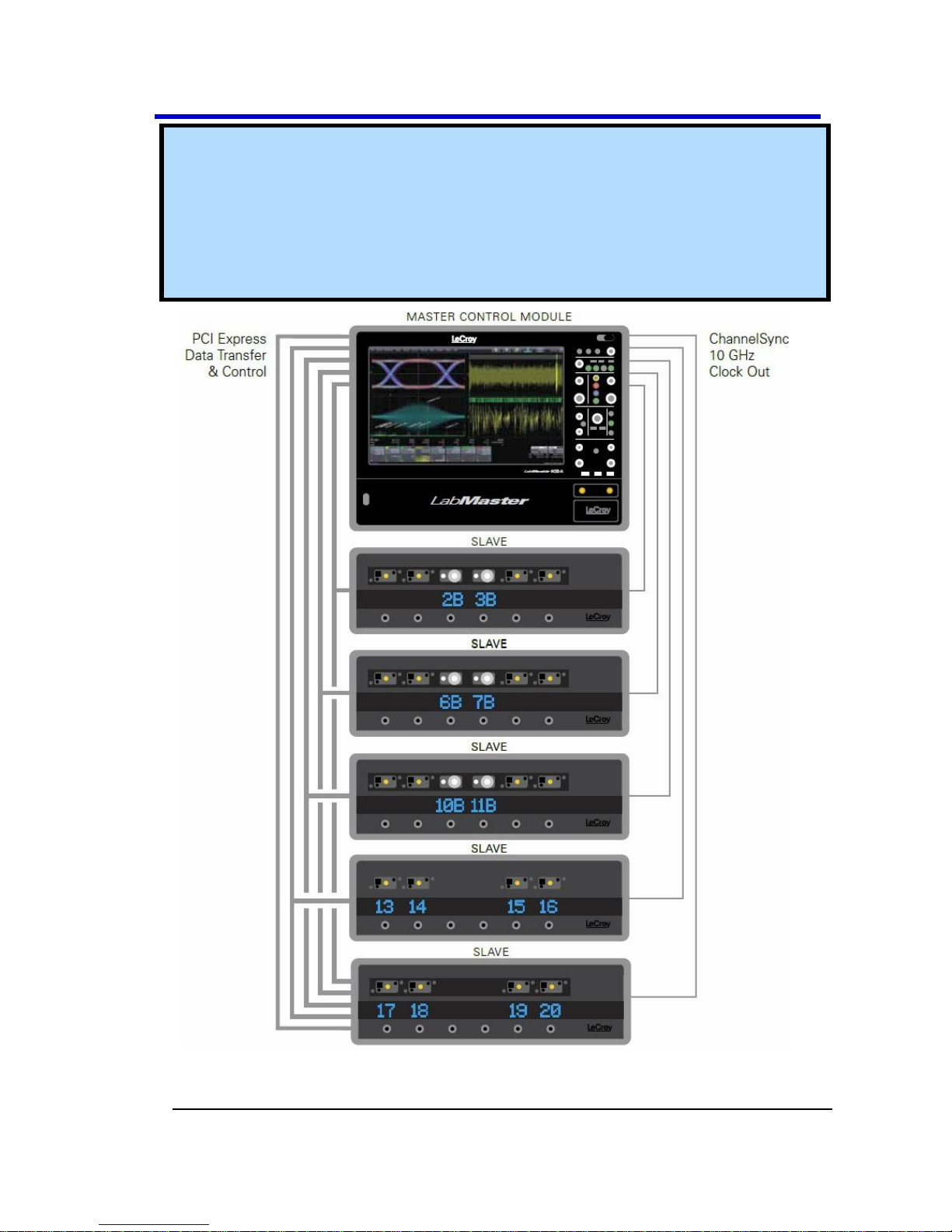
Numbered labels on this image correspond with descriptions on the
following table.
Number and Description
1. Mouse
2. Keyboard
3. Ethernet Ports
4. USB Ports
5. 15-pin VGA/WXGA
Video Input
6. 15-pin
VGA/WXGA
Video Output
7. DVI-D Video
Output
Note: Contact a system administrator when connecting to any internal
LAN.
Page 38
Getting Started Manual
LM9Zi-A-GSM-E RevA
38
The Front of Your 9xxSZi-A Slave Acquisition
Module
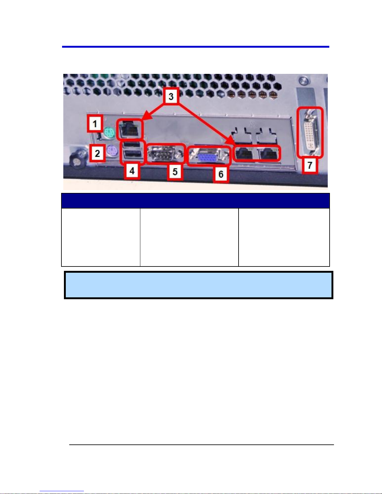
This topic shows the front of a 9xxSZi-A Slave Acquisition Module.
Numbered labels on this image correspond with descriptions on the
following table.
Number and Description
1. ProLink
Compatible
Inputs
2. 2.4/2.92 mm
Compatible
Inputs (on >20
GHz Model Slave
Acquisition
Modules Only)
3. Channel ON/OFF
Buttons
4. Corresponding
Channel Number
Indicators
PLEASE NOTE THE FOLLOWING:
If your LabMaster system runs multiple Slave Acquisition
Modules, for optimal channel access and convenience, LeCroy
recommends stacking the modules on top of each other on your
bench, inside LeCroy's available Tower or inside of your own rack
(modules must be specifically ordered for rack mounting from the
LeCroy factory).
Page 39

LabMaster 9 Zi-A Oscilloscopes
39
LM9Zi-A-GSM-E RevA
The 9xxSZi-A Slave Acquisition Modules are available in a variety
of bandwidths and channel density configurations. Each example
shown previously contains a mix of 20 GHz and >20 GHz Slave
Acquisition Modules. Each Slave Acquisition Module is
compatible with either Master Module (Control or Acquisition).
Refer to specifications on the datasheet maintained at
www.lecroy.com and contact your LeCroy representative for
details using Contact LeCroy for Support (on page 268) for more
information.
Page 40

Getting Started Manual
LM9Zi-A-GSM-E RevA
40
The Back of Your 9xxSZi-A Slave Acquisition
Module
This topic shows the back of a 9xxSZi-A Slave Acquisition Module.
Numbered labels on this image correspond with descriptions on the
following table.
Number and Description
1. ChannelSync PCIe 1
Lane Control Input
2. PCIe 4 Lane Data
Output
3. ChannelSync SMA
10 GHz Clock Input
4. AUX IN rated for 50
Ω input
5. AC
Power
Plug
PLEASE NOTE THE FOLLOWING:
Only The Back of Your 9CZi-A Master Control Module (on page
29) or The Back of Your 9xxMZi-A Master Acquisition Module (on
page 33) has 10 MHz Reference Clock Input/Output connections.
10 MHz Reference Clock Inputs are specifically intended for
synchronization with other instruments; not between Master and
Slave modules.
Page 41

LabMaster 9 Zi-A Oscilloscopes
41
LM9Zi-A-GSM-E RevA
Removing and Attaching the Front Panel Control
Detach the Front Panel Control from the oscilloscope by sliding the
detachment lever to the left and pulling at the right.
Attach the front panel by inserting the lower part first, sliding the
detachment lever to the left, and then pushing the top in place.
Page 42

Getting Started Manual
LM9Zi-A-GSM-E RevA
42
FRONT PANEL AS A REMOTE CONTROL
While detached, your front panel (standard or 4 channel version) can be
used as a remote control. Just plug-and-play connect to the oscilloscope
using the USB - A to USB - Mini B cable provided.
Note: While a standard front panel comes with your Zi oscilloscope,
LeCroy offers additional standard front panels or a 4 channel version
(as follows) to better suit the way you work. Learn more and Contact
LeCroy for Support (on page 268).
Page 43

LabMaster 9 Zi-A Oscilloscopes
43
LM9Zi-A-GSM-E RevA
Touch-Screen and External Displays
The LabMaster 9 Zi-A requires a physical connection from the CPU to the
DVI-D video input connector to enable the internal, built-in touch-
screen display.
You can use other external displays in one of the following three ways:
1. Use the optional DVI-D video output connector to drive an
external display instead of the internal touch-screen display.
2. Use the 15-pin VGA/WXGA video output connector to drive an
external display.
PLEASE NOTE THE FOLLOWING:
The CPU used in your LabMaster 9 Zi-A does not support
extended desktop mode.
Use Windows® Screen Resolution controls (from the Windows®
Control Panel) to adjust external displays connected via DVI-
D video output or 15-pin VGA/WXGA video output connections.
3. Use the LM9Zi-VIDEOCARD-Zi-EXTDISP-15 option to power the
LeCroy External Display accessory.
Note: LM9Zi-VIDEOCARD-Zi-EXTDISP-15 and other PCIe
Expansion Slot options for GPIB and LSIB must be specified when
ordering and installed at the LeCroy factory. Contact your LeCroy
representative for details using Contact LeCroy for Support (on
page 268).
LeCroy External Display (Zi-EXTDISP-15) Setup
Setting up the Zi-EXTDISP-15 involves a DVI-D and USB connections and
some touch screen selections. The USB connection is a hot swap, so
there's no need to restart the instrument once you've connected.
1. With your system powered down, plug your external display (Zi-
EXTDISP-15 option) power cord into an AC socket and the other
end into the Zi-EXTDISP-15 PCIe card. Now, plug the DVI-D plug
into the DVI-D socket on the Zi-EXTDISP-15 PCIe card.
Page 44

Getting Started Manual
LM9Zi-A-GSM-E RevA
44
2. Finally, connect your USB plug (where applicable) to an available
port.
Note: The 15-pin VGA/WXGA video output connector can be used to
drive an external display. Use Windows® Screen Resolution controls
(from the Windows® Control Panel) to adjust external displays
connected 15-pin VGA/WXGA video output connections.
2. Now, turn on the oscilloscope, let the instrument boot and then
touch Display → Display Setup... from the menu bar.
3. Touch the Open Monitor Control Panel button on the Second
Monitor Configuration section of the Display dialog.
4. The Intel® Graphics Media Accelerator Driver interface is shown
where you can adjust your second monitor settings.
Page 45

LabMaster 9 Zi-A Oscilloscopes
45
LM9Zi-A-GSM-E RevA
The following picture shows a WavePro 7 Zi with the LeCroy external
display attached (optional ZI-EXTDISP-15).
Page 46

Getting Started Manual
LM9Zi-A-GSM-E RevA
46
LabMaster Configuration Setups
Configuration Setups Overview
At this point, please take a moment to confirm the items of your order
and familiarize yourself with your LabMaster System.
These instructions explain the setup of your LabMaster modules for both
Master Control Module or Master Acquisition Module configurations. As
mentioned previously in LabMaster Hardware Overview (on page 24),
LabMaster modules are designed to work with one another for a variety
of extensible configurations and customized solution possibilities;
however, they are purchased as either Master Control Module or Master
Acquisition Module configurations.
LabMaster Setup Styles
As mentioned previously, LabMaster modules are designed to work with
one another for a variety of extensible configurations and customized
solution possibilities. They are purchased as Master Control Module or
Master Acquisition Module configurations. You can choose your own
LabMaster Setup Style - meaning, you can decide to Stack your
LabMaster modules or Rack them inside an available Tower complete
with lockable front wheels.
Note: If your LabMaster system runs multiple Slave Acquisition
Modules, for optimal channel access and convenience, LeCroy
recommends stacking the modules on top of each other on your bench,
inside LeCroy's available Tower or inside of your own rack (modules
must be specifically ordered for rack mounting from the LeCroy
factory).
Page 47

LabMaster 9 Zi-A Oscilloscopes
47
LM9Zi-A-GSM-E RevA
LabMaster Master Control Module and Master Acquisition Module Stack
Setups
LabMaster Rack Setup inside the available Tower
Page 48

Getting Started Manual
LM9Zi-A-GSM-E RevA
48
The following picture shows the back of the LabMaster Rack Setup inside
the available Tower (and the various connections made among the
modules).
Back of the LabMaster Rack Setup inside the available Tower
Page 49
LabMaster 9 Zi-A Oscilloscopes
49
LM9Zi-A-GSM-E RevA
Master Control Module Configuration Setup
Connecting Your LabMaster Overview
The steps for connecting your LabMaster involve PCIe 1 and 4 Lane, DVID, SMA 72", and Power Cable connections. Use the following topics to
properly connect all parts of your LabMaster setup.
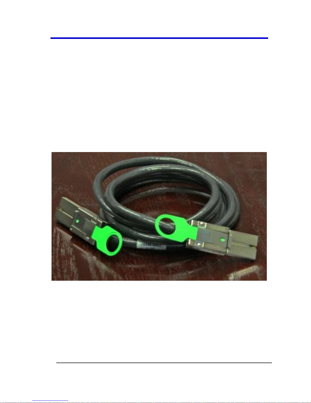
PCIe 1 Lane Cable - Master Control Module to Slave
Acquisition Module SYNC Connection(s)
Connect each PCIe 1 Lane Control Output on the back of your 9CZi-A
Master Control Module to the PCIe 1 Lane Input on each 9xxSZi-A Slave
Acquisition Module used in your system using the PCIe 1 Lane cable(s)
provided.
PCIe 1 Lane Cable
Page 50

Getting Started Manual
LM9Zi-A-GSM-E RevA
50
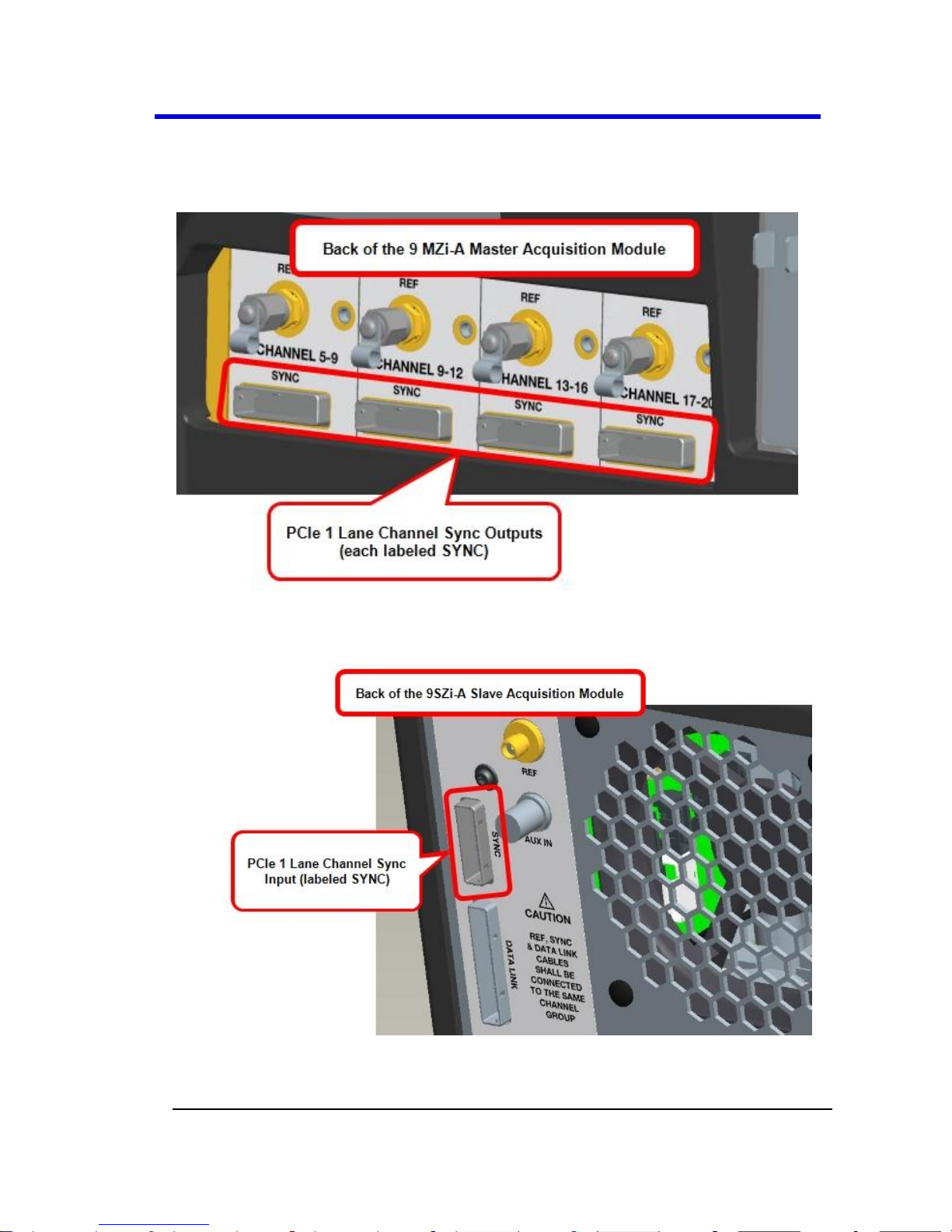
On the back of the Master Control Module, plug one end of the
PCIe 1 Lane cable into the PCIe 1 Lane Channel Sync Output
(labeled SYNC).
Page 51
LabMaster 9 Zi-A Oscilloscopes
51
LM9Zi-A-GSM-E RevA
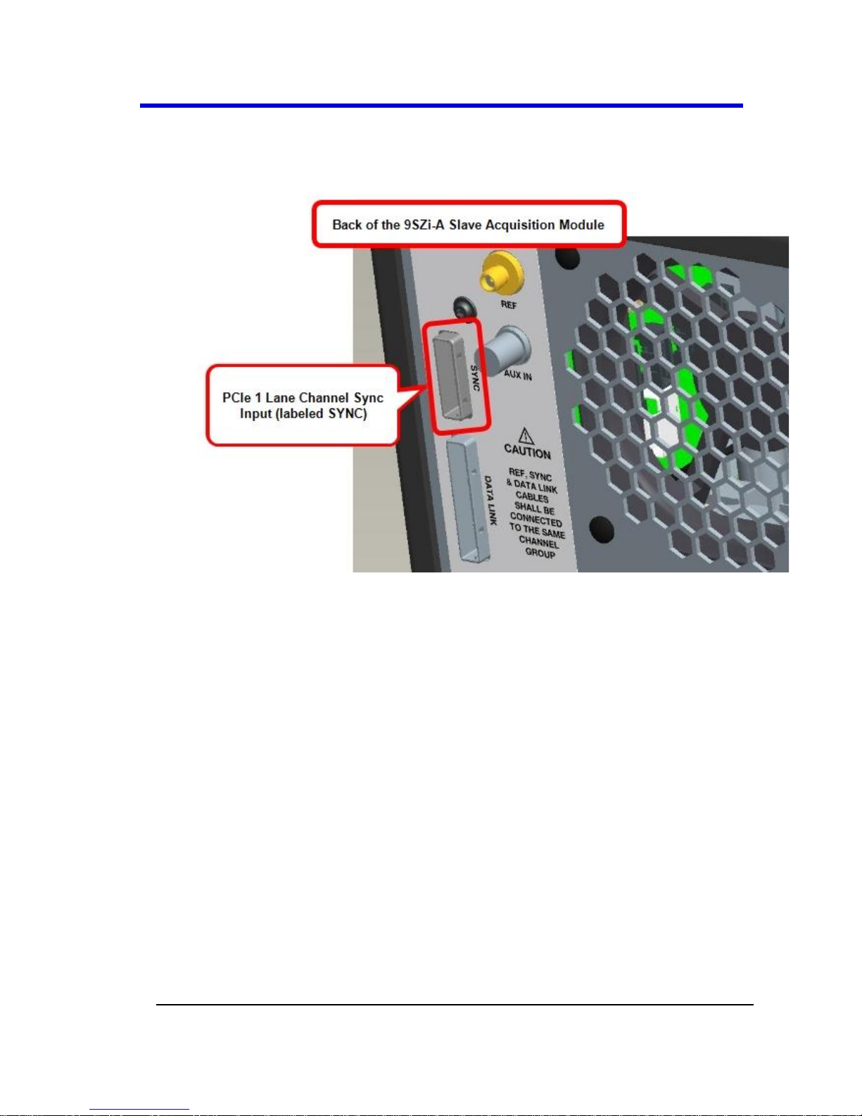
Now, on the back of the Slave Acquisition Module, connect the
other end of the same PCIe 1 Lane cable into the corresponding
PCIe 1 Lane Channel Sync Input (labeled SYNC).
Repeat the previous steps for every additional Slave Acquisition
Module in your system.
PLEASE NOTE THE FOLLOWING:
PCIe 1 Lane Cable plugs are keyed with a single groove along one
wide side of the plug. The plug must be inserted into the socket
with the groove aligned properly.
Connect into your Slave Acquisition Modules from the correct
channel groupings on the 9CZi-A Master Control Module;
meaning, your first Slave Acquisition Module is connected from
the CHANNEL 1-4 output, second from the CHANNEL 5-9 output,
third from the CHANNEL 9-12 output, fourth from the CHANNEL
13-16 output, and last from the CHANNEL 17-20 output.
Page 52
Getting Started Manual
LM9Zi-A-GSM-E RevA
52
If you are connecting less than 5 of the Slave Acquisition
Modules, the PCIe 1 Lane Channel Sync Outputs on the back of
the Master Control Module may not be skipped and must be
connected in consecutive order into the PCIe 1 Lane Channel Sync
Inputs on the back of the corresponding slaves.
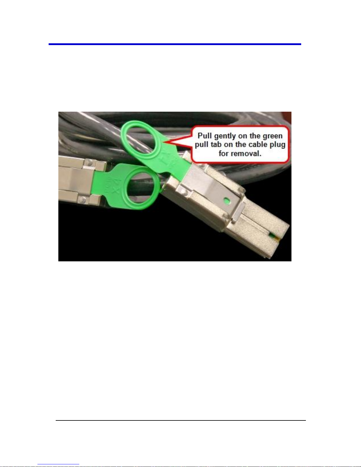
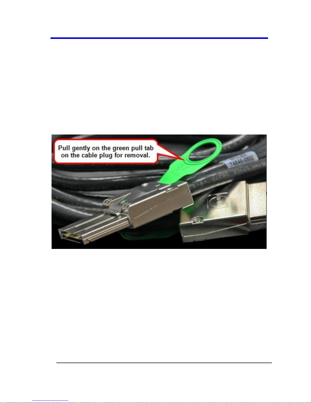
Pull gently on the green pull tab on the cable plug for removal.
Page 53
LabMaster 9 Zi-A Oscilloscopes
53
LM9Zi-A-GSM-E RevA
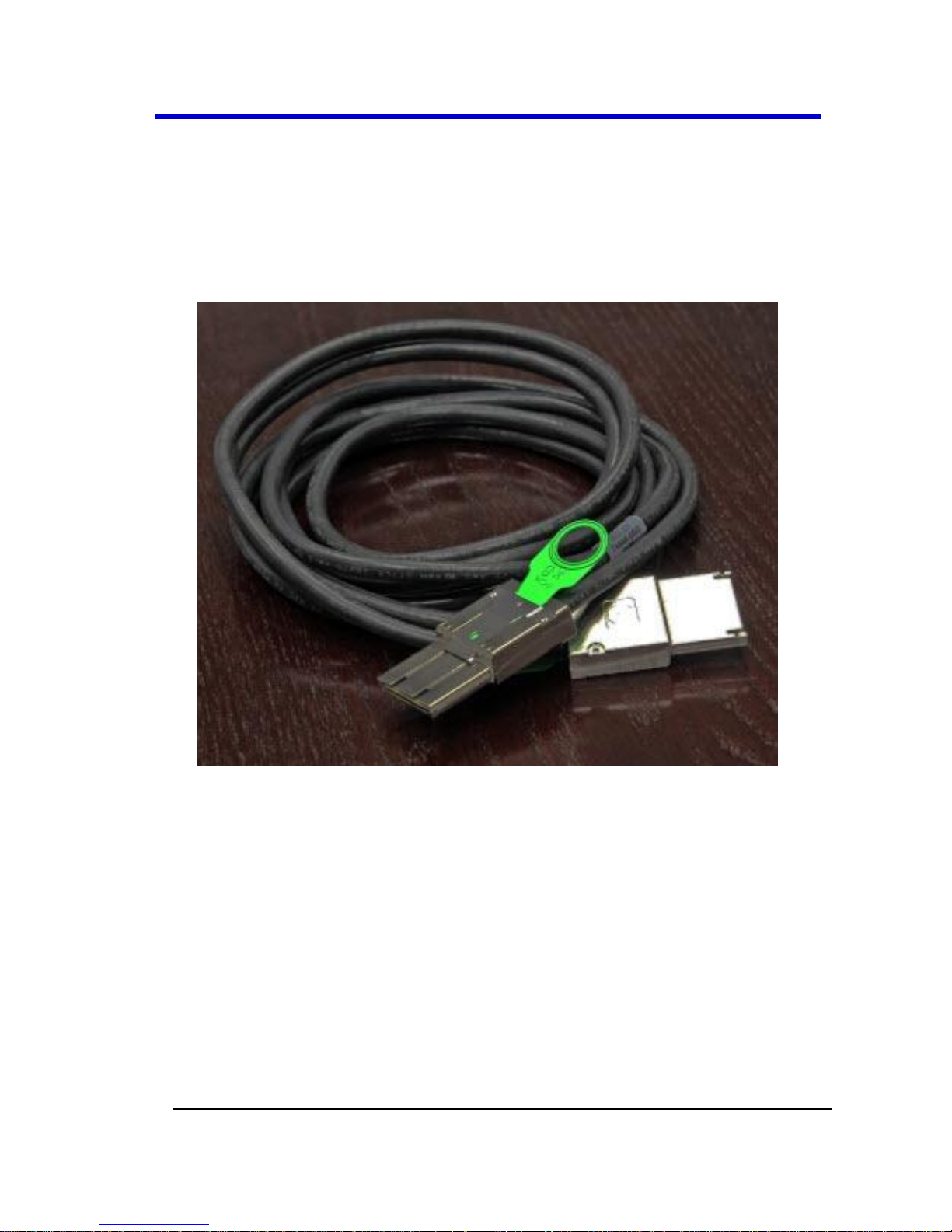
PCIe 4 Lane Cable - Slave Acquisition Module to Master
Control Module SYNC Connection(s)
Now, let's continue making the PCI Express connections by cabling the
PCIe 4 Lane Data Output on the back of each 9xxSZi-ASlave Acquisition
Module to the PCIe 4 Lane Data Inputs on the back of your 9CZi-AMaster
Control Module using PCIe 4 Lane cable(s) provided.
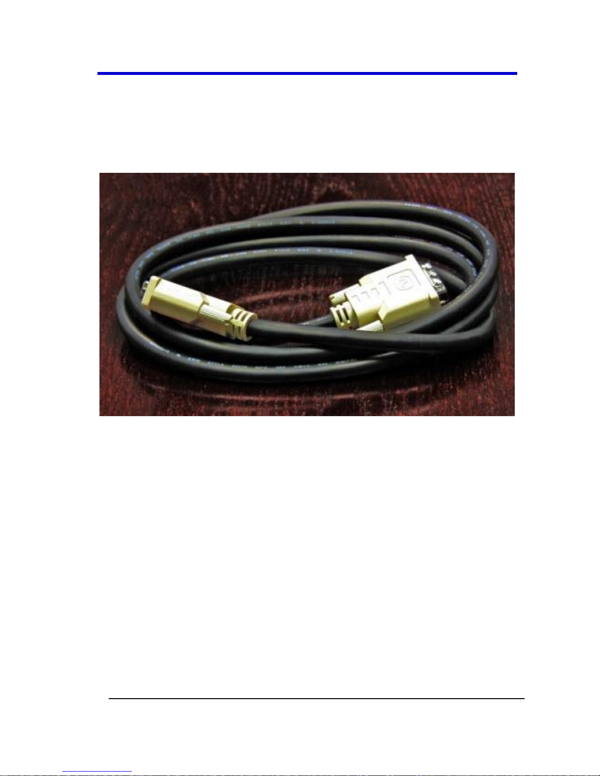
PCIe 4 Lane Cable
Page 54
Getting Started Manual
LM9Zi-A-GSM-E RevA
54
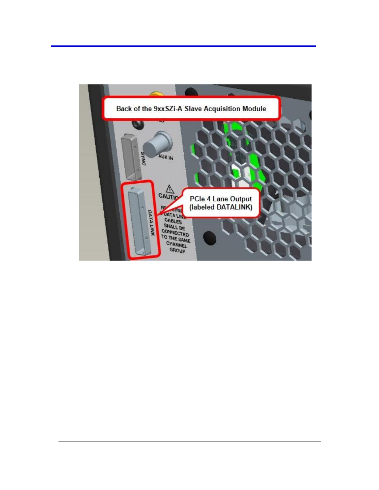
On the back of a Slave Acquisition Module, connect one end of a
PCIe 4 Lane cable from the PCIe 4 Lane Data Output (labeled
DATALINK).
Page 55

LabMaster 9 Zi-A Oscilloscopes
55
LM9Zi-A-GSM-E RevA
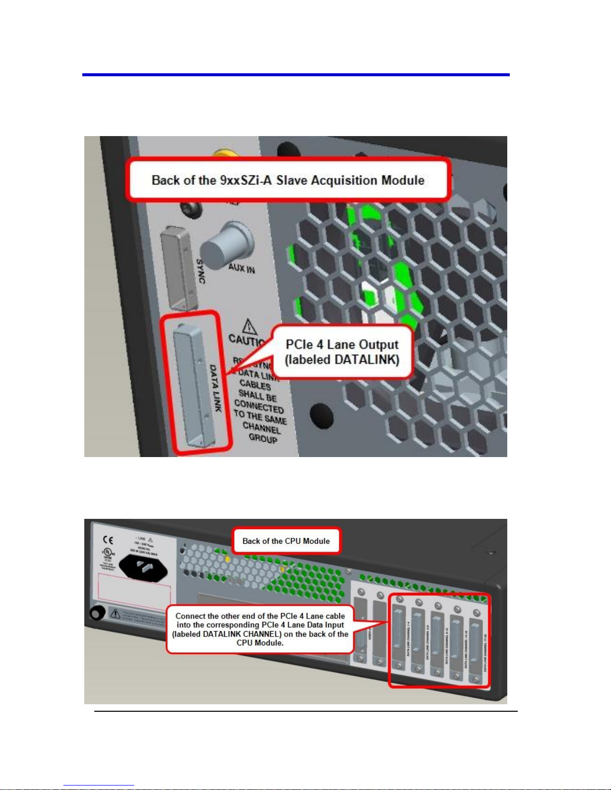
Now, on the back of the Master Control Module, connect the
other end of the same PCIe 4 Lane cable into the corresponding
PCIe 4 Lane Data Input (labeled DATALINK CHANNEL).
Repeat the previous steps for every additional Slave Acquisition
Module in your system.
PLEASE NOTE THE FOLLOWING:
PCIe 4 Lane Cable plugs are keyed with a single groove along one
wide side of the plug. The plug must be inserted into the socket
with the groove aligned properly.
Page 56

Getting Started Manual
LM9Zi-A-GSM-E RevA
56
Be sure to connect from your Slave Acquisition Modules into the
correct channel groupings on the 9CZi-A Master Control Module;
meaning, your first Slave Acquisition Module is connected into
DATALINK CHANNEL 1-4 input on the Master Control Module,
second into the DATALINK CHANNEL 5-9 input, third into the
DATALINK CHANNEL 9-12 input, fourth into the
DATALINK CHANNEL 13-16 input, and last into the
DATALINK CHANNEL 17-20 input.
If you are connecting less than 5 of the Slave Acquisition
Modules, the PCIe 4 Lane Data Inputs on the back of the Master
Control Modulemay not be skipped and must be connected in
consecutive order from the PCIe 4 Lane Data Outputs on the back
of the corresponding slaves.
Pull gently on the green pull tab on the cable plug for removal.
Page 57
LabMaster 9 Zi-A Oscilloscopes
57
LM9Zi-A-GSM-E RevA
DVI-D Connection - Connecting the Video Card to the
Touch-Screen Display on the Master Control Module
The DVI-D Video Output must be connected to the DVI-D Video Input
(both on the back of the Master Control Module) using the provided DVI-
D cable for the touch-screen display to function.
DVI-D Cable
Connect one end of the provided DVI-D cable into the DVI-D Video
Output on the back of the Master Control Module.
Page 58

Getting Started Manual
LM9Zi-A-GSM-E RevA
58
Now, connect the other end of the same DVI-D cable into the DVI-D
Video Input, also on the back of the Master Control Module.
Note: The connections are specifically DVI-D.
The connections are specifically DVI-D.
Page 59

LabMaster 9 Zi-A Oscilloscopes
59
LM9Zi-A-GSM-E RevA
SMA 72" Cables - Master Control Module to Slave
Acquisition Module Connection(s) for Reference Clock
Connect each SMA 10 GHz Clock Output on the back of your 9CZi-A
Master Control Module to the SMA 10 GHz Clock Input on each 9xxSZi-A
Slave Acquisition Module used in your system using the SMA 72"
cable(s) provided.
Note: Use an SMA torque wrench and ensure connections are properly
tightened.
SMA 72" M to M Cable
Page 60

Getting Started Manual
LM9Zi-A-GSM-E RevA
60
On the back of the Master Control Module, connect one end of an
SMA 72" cable from a SMA 10 GHz Clock Output (labeled REF,
unscrew the chain-linked 50 Ω termination, if necessary) .
Now, on the back of the Slave Acquisition Module, connect the
other end of the same SMA 72" cable into the corresponding SMA
10 GHz Clock Input (labeled REF).
Page 61

LabMaster 9 Zi-A Oscilloscopes
61
LM9Zi-A-GSM-E RevA
Repeat the previous steps for every additional Slave Acquisition
Module in your system.
Note: Cap off any unused SMA 10 GHz Clock Outputs on the back of
your 9CZi-A Master Control Module using the chain-linked 50 Ω
terminations provided.
Power Cable Connections and Main Power Switch
The combined draw from your 9CZi-A Master Control Module and
9xxSZi-A Slave Acquisition Modules (max of 5) approximately totals 5
kW, LeCroy advises that your power connections be generally divided as
follows:
The Master Control Module requires less power and may be
combined with a Slave Acquisition Module to a different circuit
rated to handle a combined 2050 Watts.
Connect any additional pairs of Slave Acquisition Modules to a
different circuit rated to handle a combined 2050 Watts.
PLEASE NOTE THE FOLLOWING:
Refer to LabMaster Setup Styles (on page 46) for more setup
information.
Always refer to the regularly-maintained datasheet specifications
for the most current and detailed information at
www.lecroy.com.
Page 62

Getting Started Manual
LM9Zi-A-GSM-E RevA
62
15A/250V 14AWG rated grounded cord set with a IEC320 right-
angle Type C15 connector with a slotted groove is provided
specifically for the Master Control Module. Components other
than the Master Control Module are each provided with a
standard 10A/250V 18AWG rated grounded cord set with an
IEC320 right-angle Type C13 connector.
Page 63

LabMaster 9 Zi-A Oscilloscopes
63
LM9Zi-A-GSM-E RevA
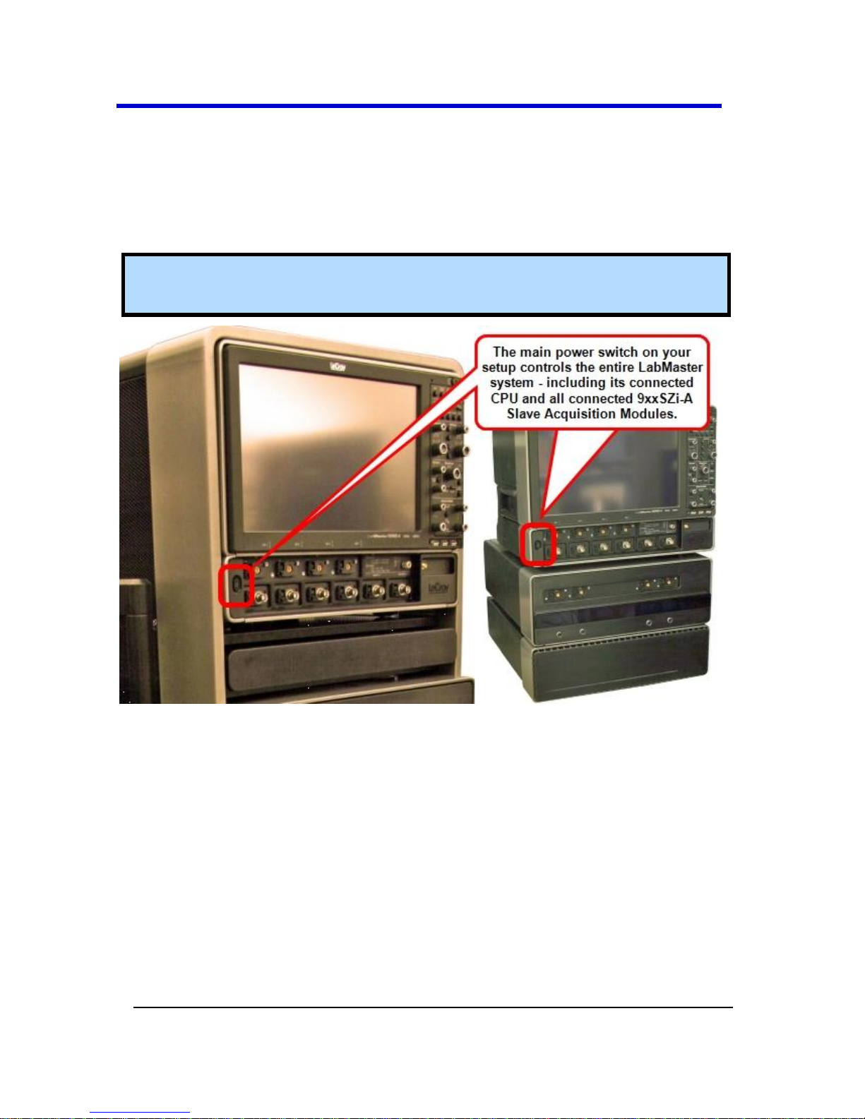
MAIN POWER SWITCH
When all connections are made, the main switch on the front of the
Master Control Module powers all connected items - Master and Slave
Acquisition Module(s) - as a single LabMaster unit.
Tip: If any connections are incorrect, the main power switch does not
power on your system.
Page 64

Getting Started Manual
LM9Zi-A-GSM-E RevA
64
Master Acquisition Module Configuration Setup
Connecting Your LabMaster Overview
The steps for connecting your LabMaster involve PCIe 1 and 4 Lane, DVID, SMA 72", and Power Cable connections. Use the following topics to
properly connect all parts of your LabMaster setup.
PCIe 1 Lane Cable - Master Acquisition Module to Slave
Acquisition Module Connection(s)
Connect each PCIe 1 Lane Control Output on the back of your 9xxMZi-A
Master Acquisition Module to the PCIe 1 Lane Input on each 9xxSZi-A
Slave Acquisition Module used in your system using the PCIe 1 Lane
cable(s) provided.
PCIe 1 Lane Cable
Page 65
LabMaster 9 Zi-A Oscilloscopes
65
LM9Zi-A-GSM-E RevA
On the back of the Master Acquisition Module, plug one end of
the PCIe 1 Lane cable into the PCIe 1 Lane Channel Sync Output
(labeled SYNC).
Now, connect the other end of the 1 Lane cable into the SYNC
socket on the back of the 9 SZi-A (Slave).
Repeat the previous steps for every additional Slave Acquisition
Module in your system.
Page 66

Getting Started Manual
LM9Zi-A-GSM-E RevA
66
PLEASE NOTE THE FOLLOWING:
PCIe 1 Lane Cable plugs are keyed with a single groove along one
wide side of the plug. The plug must be inserted into the socket
with the groove aligned properly.
Connect into your Slave Acquisition Modules from the correct
channel groupings on the 9xxMZi-A Master Acquisition Module;
meaning, your first Slave Acquisition Module is connected from
the CHANNEL 5-9 output, second from the CHANNEL 9-12 output,
third from the CHANNEL 13-16 output, and last from the
CHANNEL 17-20 output.
If you are connecting less than 4 of the Slave Acquisition
Modules, the PCIe 1 Lane Channel Sync Outputs on the back of
the Master Acquisition Module may not be skipped and must be
connected in consecutive order into the PCIe 1 Lane Channel Sync
Inputs on the back of the corresponding slaves.
Pull gently on the green pull tab on the cable plug for removal.
Page 67

LabMaster 9 Zi-A Oscilloscopes
67
LM9Zi-A-GSM-E RevA
PCIe 4 Lane Cable - CPU Module to Master Acquisition
Module Connection(s)
We first have to make a specific connection for Channels 1-4 from the
back of the Master Acquisition Module into the PCIe 4 Lane Data Input
(labeled DATALINK CHANNEL 1-4) on the back of the CPU Module.
PCIe 4 Lane Cable
Page 68

Getting Started Manual
LM9Zi-A-GSM-E RevA
68
First, connect one end of a PCIe 4 Lane cable to the PCIe 4 Lane
Data Output (labeled DATALINK CHANNEL 1-4) on the back of the
Master Acquisition Module.
Note: The PCIe 4 Lane Data Output on the back of the 9xxMZiAMaster Acquisition Module must be specifically plugged into
the PCIe 4 Lane Data Input on the back of the CPU Module.
Page 69

LabMaster 9 Zi-A Oscilloscopes
69
LM9Zi-A-GSM-E RevA
Now, on the back of the CPU Module, connect the other end of
the same PCIe 4 Lane cable specifically into the PCIe 4 Lane Data
Input (labeled DATALINK CHANNEL 1-4).
9xxSZi-ASlave Acquisition Modules connections for channels
above 1-4, connections are made from the PCIe 4 Lane Data
Output (labeled DATALINK CHANNEL) on the back of each Slave
Acquisition Module into the corresponding PCIe 4 Lane Data
Input (labeled DATALINK CHANNEL) on the back of the CPU
Module.
PLEASE NOTE THE FOLLOWING:
PCIe 4 Lane Cable plugs are keyed with a single groove along one
wide side of the plug. The plug must be inserted into the socket
with the groove aligned properly.
Page 70

Getting Started Manual
LM9Zi-A-GSM-E RevA
70
If you are connecting less than 4 of the Slave Acquisition
Modules, the PCIe 4 Lane Data Inputs on the back of the CPU
Modulemay not be skipped and must be connected in
consecutive order from the PCIe 4 Lane Data Outputs on the back
of the corresponding slaves.
Pull gently on the green pull tab on the cable plug for removal.
Page 71

LabMaster 9 Zi-A Oscilloscopes
71
LM9Zi-A-GSM-E RevA
PCIe 4 Lane Cable - Slave Acquisition Module to CPU
Module Connection(s)
Now, let's continue making the PCI Express connections for channels
above 1-4, by cabling the PCIe 4 Lane Data Output on the back of each
9xxSZi-ASlave Acquisition Module to the PCIe 4 Lane Data Inputs on the
back of your CPU Module using PCIe 4 Lane cable(s) provided.
PCIe 4 Lane Cable
Page 72
Getting Started Manual
LM9Zi-A-GSM-E RevA
72
Plug one end of a PCIe 4 Lane cable into the PCIe 4 Lane Data
Output (labeled DATALINK) on the back of each Slave Acquisition
Module.
Now, on the back of the CPU Module, connect the other end of
the same PCIe 4 Lane cable into the corresponding PCIe 4 Lane
Data Input (labeled DATALINK CHANNEL).
Page 73
LabMaster 9 Zi-A Oscilloscopes
73
LM9Zi-A-GSM-E RevA
PLEASE NOTE THE FOLLOWING:
PCIe 4 Lane Cable plugs are keyed with a single groove along one
wide side of the plug. The plug must be inserted into the socket
with the groove aligned properly.
If you are connecting less than 4 of the Slave Acquisition
Modules, the PCIe 4 Lane Data Inputs on the back of the CPU
Modulemay not be skipped and must be connected in
consecutive order from the PCIe 4 Lane Data Outputs on the back
of the corresponding slaves.
Pull gently on the green pull tab on the cable plug for removal.
Page 74

Getting Started Manual
LM9Zi-A-GSM-E RevA
74
DVI-D Connection - Connecting the CPU Module's Video
Card Output into the Master Acquisition Module's TouchScreen Display Video Input
Connect the CPU Module's Video Card DVI-D Output into the Master
Acquisition Module's Touch-Screen Display DVI-D Input using the DVI-D
cable provided.
DVI-D Cable
Page 75

LabMaster 9 Zi-A Oscilloscopes
75
LM9Zi-A-GSM-E RevA
Connect one end of the provided DVI-D cable into the DVI-D Video
Output on the back of the CPU Module.
Now, connect the other end of the same DVI-D cable into the DVI-D
Video Input on the back of the Master Acquisition Module.
Page 76

Getting Started Manual
LM9Zi-A-GSM-E RevA
76
Note: The connections are specifically DVI-D.
The connections are specifically DVI-D.
SMA 72" Cables - Master Acquisition Module to Slave
Acquisition Module Connection(s) for Reference Clock
Connect each SMA 10 GHz Clock Output on the back of your 9xxMZi-A
Master Acquisition Module to the SMA 10 GHz Clock Input on each
9xxSZi-A Slave Acquisition Module used in your system using the SMA
72" cable(s) provided.
Note: Use an SMA torque wrench and ensure connections are properly
tightened.
SMA 72" M to M Cable
Page 77

LabMaster 9 Zi-A Oscilloscopes
77
LM9Zi-A-GSM-E RevA
On the back of the Master Acquisition Module, connect one end
of an SMA 72" cable from a SMA 10 GHz Clock Output (labeled
REF, unscrew the chain-linked 50 Ω termination, if necessary).
Now, on the back of the Slave Acquisition Module, connect the
other end of the same SMA 72" cable into the corresponding SMA
10 GHz Clock Input (labeled REF).
Page 78

Getting Started Manual
LM9Zi-A-GSM-E RevA
78
Repeat the previous steps for every additional Slave Acquisition
Module in your system.
Note: Cap off any unused SMA 10 GHz Clock Outputs on the back of
your 9xxMZi-A Master Acquisition Module using the chain-linked 50 Ω
terminations provided.
Power Cable Connections and Main Power Switch
The combined draw from your 9xxMZi-AMaster Acquisition Module,
9xxSZi-ASlave Acquisition Modules (max of 4), and CPU Module
approximately totals 5 kW, LeCroy advises that your power connections
be generally divided as follows:
Connect the Master Acquisition Module and its CPU Module to a
single circuit rated to handle a combined 1250 Watts.
Connect any additional pairs of Slave Acquisition Modules to a
different circuit rated to handle a combined 2050 Watts.
PLEASE NOTE THE FOLLOWING:
Refer to LabMaster Setup Styles (on page 46) for more setup
information.
Page 79

LabMaster 9 Zi-A Oscilloscopes
79
LM9Zi-A-GSM-E RevA
Always refer to the regularly-maintained datasheet specifications
for the most current and detailed information at
www.lecroy.com.
15A/250V 14AWG rated grounded cord set with a IEC320 right-
angle Type C15 connector with a slotted groove is provided
specifically for the Master Acquisition Module. Components other
than the Master Acquisition Module are each provided with a
standard 10A/250V 18AWG rated grounded cord set with an
IEC320 right-angle Type C13 connector.
Page 80
Getting Started Manual
LM9Zi-A-GSM-E RevA
80
MAIN POWER SWITCH
When all connections are made, the main switch on the front of the
Master Acquisition Module powers all connected items (Master
Acquisition, Slave Acquisition, and CPU Module) as a single LabMaster
unit.
Tip: If any connections are incorrect, the main power switch does not
power on your system.
Page 81

LabMaster 9 Zi-A Oscilloscopes
81
LM9Zi-A-GSM-E RevA
Basic Controls
Hardware and Software Controls
The following Basic Control topics cover the general usage of the
hardware buttons located on the oscilloscope's front panel and the
screen control interface elements of the software.
Front Panel Controls
Note: Many specific Front Panel Controls directly correspond with
Screen Layout Controls. For example, the Print front panel general
control button corresponds with the Hardcopy function at Utilities →
Utilities Setup → Hardcopy.
Page 82
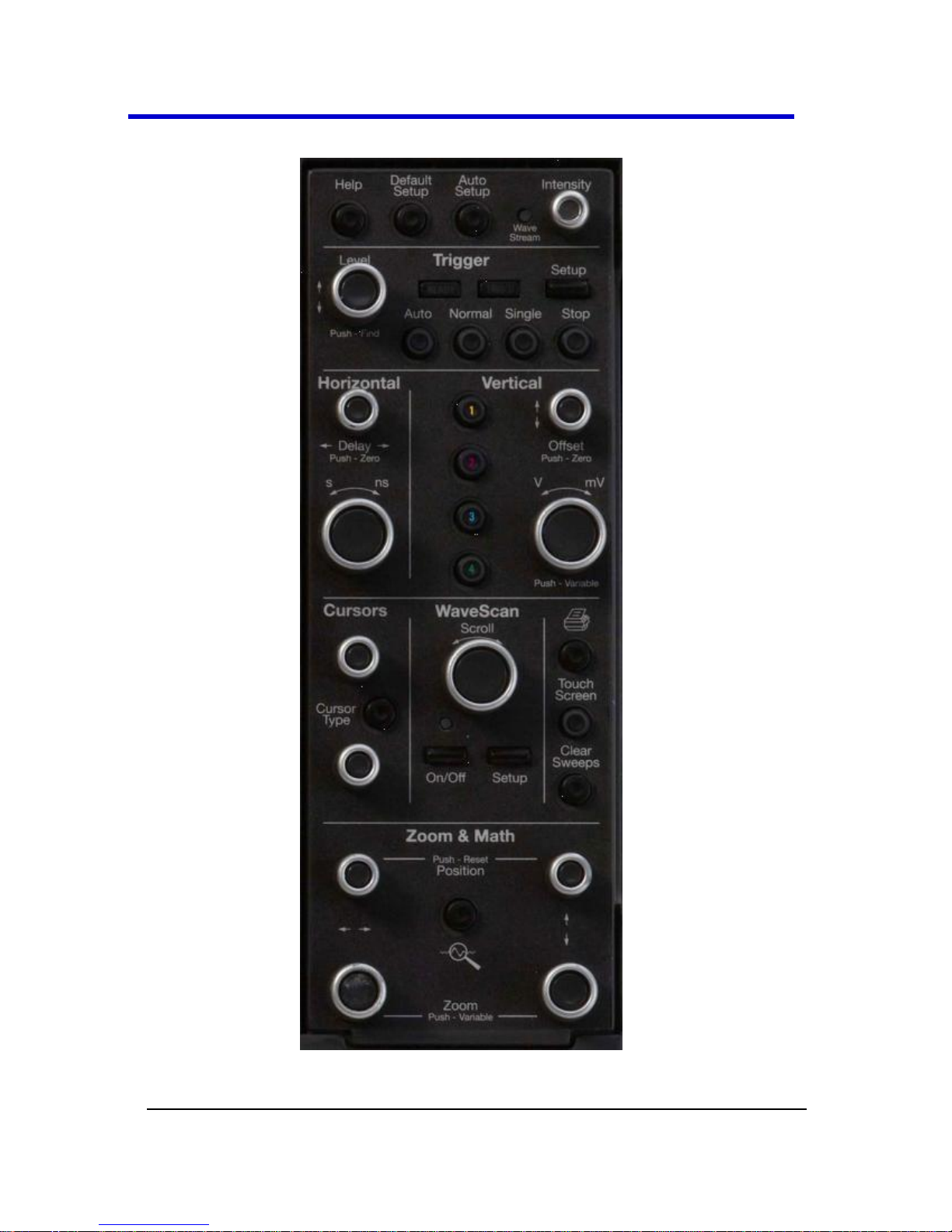
Getting Started Manual
LM9Zi-A-GSM-E RevA
82
The following picture shows the Front Panel Control.
Front Panel for LabMaster, WaveMaster, and WavePro, Zi and Zi-A
oscilloscopes.
Page 83

LabMaster 9 Zi-A Oscilloscopes
83
LM9Zi-A-GSM-E RevA
Front Panel Control Groupings
Front Panel Control Groupings Overview
The front panel is divided into sections based on various functions. The
following topics explain these sections in more detail.
Miscellaneous Setup Controls and WaveStream Indicator
Help - Press to open the LeCroy Online Assistant where you can
click to open the oscilloscope online help table of contents, index,
or search for a topic using a keyword. If the second monitor is
installed, the online help opens on the second monitor.
Default Setup - Press to reset the oscilloscope's settings to the
default configuration. Corresponds with screen menu selection:
File → Recall Setup → Recall Default Setup.... For a list of default
settings, see Save/Recall → Saving and Recalling Setups (on page
230).
Auto Setup - Press once and the Auto Setup... flyout menu opens.
OR
From the menu bar, touch the Auto Setup... selection from the
Vertical, Timebase, or Trigger menus.
Press the Auto Setup... button on the flyout menu to perform a
full auto setup. Press a Channel Find Scale button on the flyout
menu to perform a quick auto setup for that channel only.
Page 84
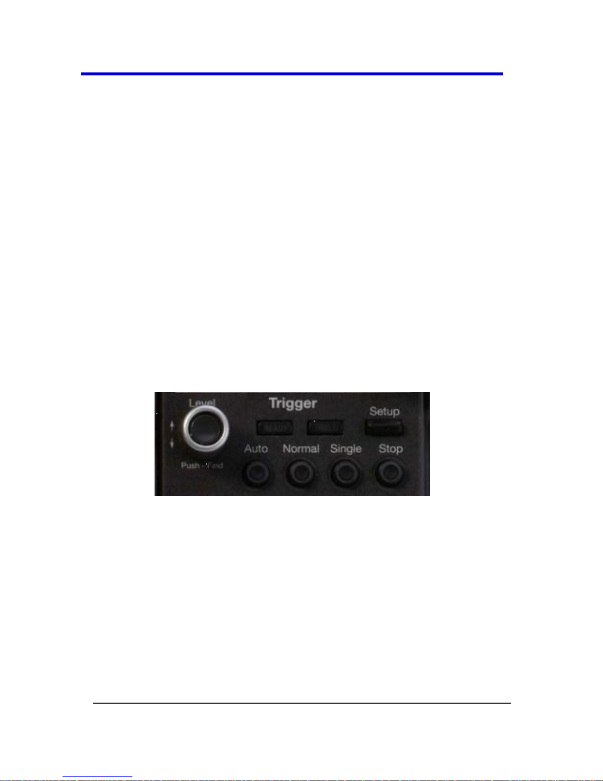
Getting Started Manual
LM9Zi-A-GSM-E RevA
84
Press the AUTO SETUP... front panel button twice to perform the
last selection from the Auto Setup... flyout menu (the default is to
perform a full auto setup).
If Auto Setup is run when no channels are turned on, all channels
are affected. When more than one channel is turned on, the first
channel with a signal applied to it is automatically set up for edge
triggering.
Perform an autosetup of all these functions together by pressing
the Auto Setup... front panel button.
WaveStream - Indicates when WaveStream mode is ON.
Intensity - Press to toggle between WaveStream OFF and ON for
Analog Persistence and WaveStream ON for Color Persistence.
When you turn the knob, if WaveStream is ON, the WaveStream
display intensity changes. When you turn the knob, if WaveStream
is OFF, changes the Intensity setting. Corresponds with the screen
menu selection: Display → Display Setup (on page 167).
Trigger Front Panel Controls
Level - Pressing this button sets the trigger level to 50%. Turn the
knob to change the trigger threshold level. The threshold level is
indicated on the Trigger label.
READY and TRIG'D Indicators - The READY indicator is lit when the
trigger is armed. TRIG'D is lit momentarily when a trigger occurs. A
fast trigger rate causes the light to stay lit continuously.
Setup - Press once to open the Trigger Setup... dialog.
Corresponds with screen menu selection: Trigger → Trigger
Setup.... Press the Trigger SETUP front panel button again to close
the Trigger Setup... dialog.
Page 85
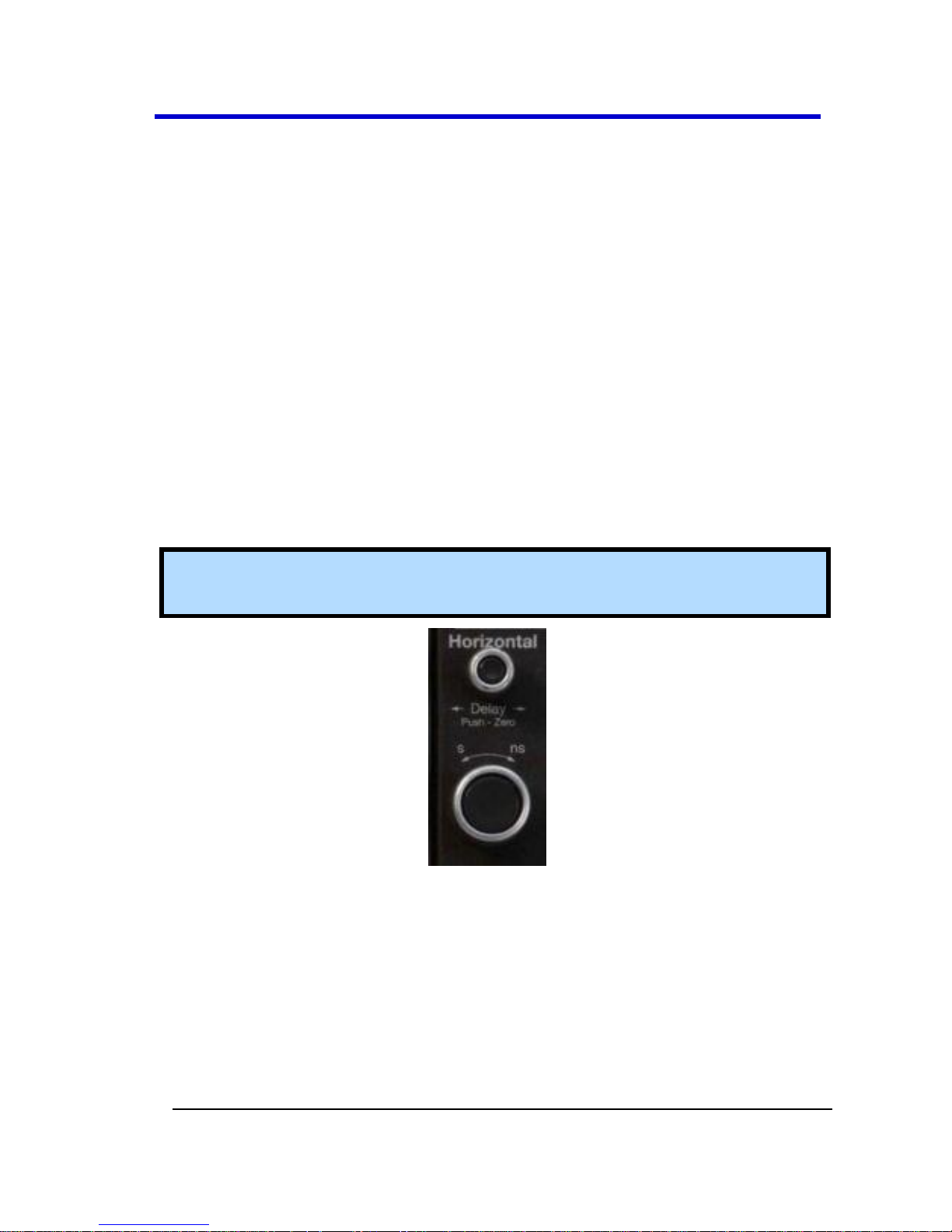
LabMaster 9 Zi-A Oscilloscopes
85
LM9Zi-A-GSM-E RevA
Auto - Press to turn on Auto Trigger mode, which triggers the
oscilloscope after a time-out, even if the trigger conditions are not
met.
Normal - Press to turn on Normal Trigger mode, which triggers the
oscilloscope each time a signal is present that meets the
conditions set for the type of trigger selected.
Single - Press to turn on Single Trigger mode, which arms the
oscilloscope to trigger once (single-shot acquisition) when the
input signal meets the trigger conditions set for the type of trigger
selected. If the scope is already armed, it will force a trigger.
Stop - Press to prevent the scope from triggering on a signal. If you
boot up the instrument with the trigger in Stop mode, a no trace
available message is shown. Press the Trigger AUTO front panel
button to display your trace.
Horizontal Front Panel Controls
Note: Horizontal front panel controls correspond with screen menu
selection: Timebase → Horizontal Setup....
Delay - Press to toggle between a zero horizontal delay value and
the previous horizontal delay value. Turn to change the horizontal
delay value.
Time/Div - Turn to set the time/division of the oscilloscope
timebase (acquisition system).
Page 86

Getting Started Manual
LM9Zi-A-GSM-E RevA
86
Vertical Front Panel Controls
Note: You can turn channels on and off using the software as explained
in Vertical Overview (on page 133), from The Front of Your 9xxSZi-A
Slave Acquisition Module (on page 38) or from the The Front of Your
9xxMZi-A Master Acquisition Module (on page 30), where applicable.
Channels - The channel buttons control both channel ON/OFF and
which channel is active for the Vertical Offset and Volts/Div knobs
controls. If a channel is OFF, pressing that channel button turns it
on and makes it active. If a channel button is ON, pressing that
channel button makes it active, and then pressing it a second time
turns it OFF.
Offset - Press to toggle between a zero vertical offset value and
the previous vertical offset value for the selected channel. Turn to
change the vertical offset value for the selected channel.
Gain - Press to toggle between fixed and variable gain adjustment.
Turn to change the gain value.
Page 87
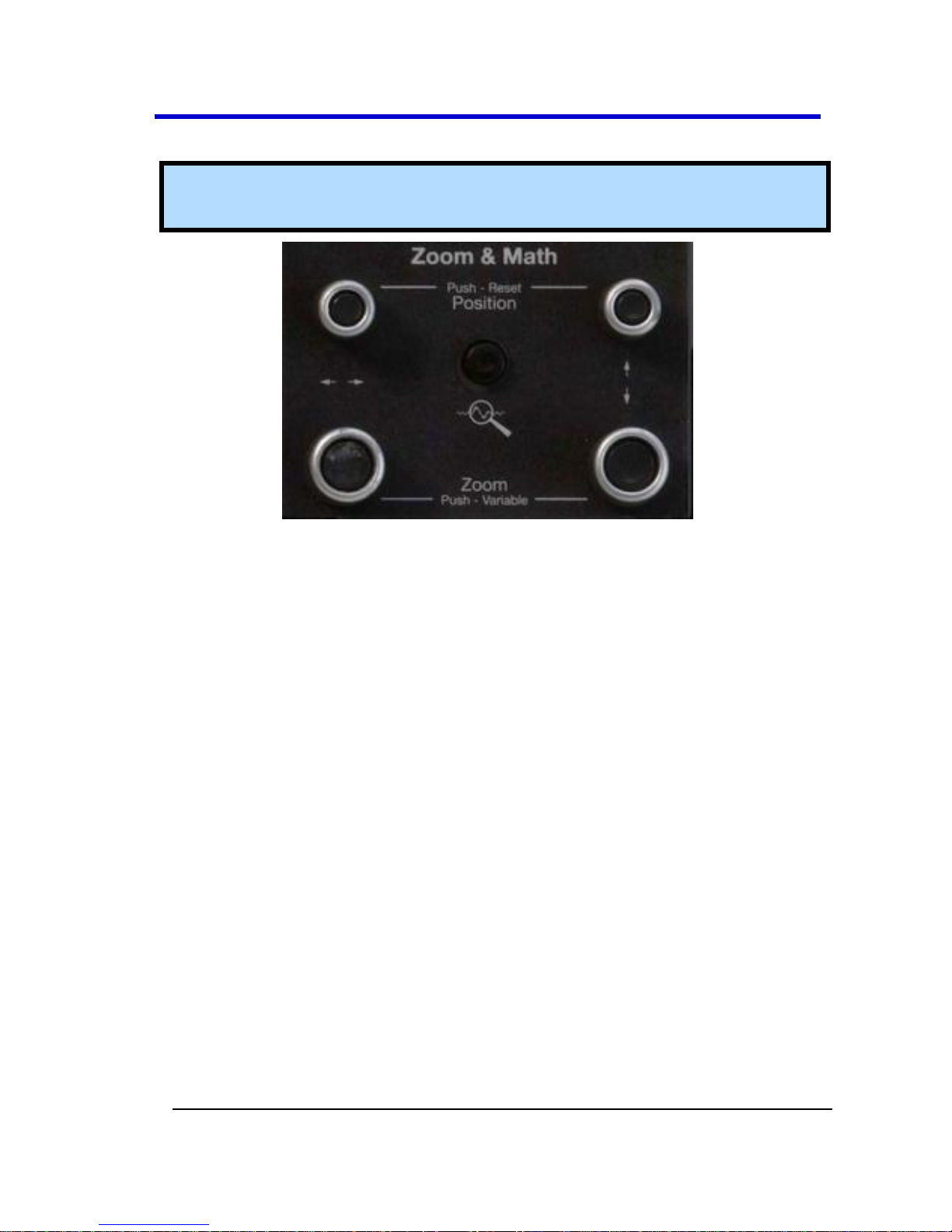
LabMaster 9 Zi-A Oscilloscopes
87
LM9Zi-A-GSM-E RevA
Zoom and Math Front Panel Controls
Note: Zoom and Math front panel controls correspond with screen
menu selection: Math → Zoom Setup....
Horizontal Position - Press to reset the horizontal zoom position
to zero. Turn to change the horizontal position of the selected
math or zoom trace.
Horizontal Ratio - Press to toggle between fixed and variable
horizontal zoom ratio adjustment. Turn to change the horizontal
zoom ratio of the selected math trace.
Quick Zoom - Press to automatically display magnified views of up
to four signal inputs on multiple grids. With four input signals, the
signals are displayed along with four zoom traces, each on its own
grid. Pressing this button also turns off all other traces.
Vertical Position - Press to reset the vertical zoom position to
zero. Turn to change the vertical position of the selected math or
zoom trace.
Vertical Ratio - Press to toggle between fixed and variable vertical
zoom ratio adjustment. Turn to change the vertical zoom ratio of
the selected math trace.
Page 88

Getting Started Manual
LM9Zi-A-GSM-E RevA
88
Probe and Signal Connection
Interfaces
Probe and Signal Connection Interfaces
Overview
LeCroy oscilloscopes are equipped with a variety of connection interfaces
to allow connection of cables directly to the oscilloscope channels, or to
allow probe connections to the oscilloscope. When probes are
connected, a probe interface is used to power the probe (as necessary),
to recognize the probe type and its characteristics, and to communicate
to and from the probe to completely integrate the probe with the
oscilloscope channel in a number of ways. For instance, active singleended and differential voltage probes and current probes use these
interfaces upload gain and offset correction factors from the probe
EEPROM's and, in some cases, automatically compensates responses to
achieve fully-calibrated measurements.
Some oscilloscope product series support multiple probe and connection
interfaces. This can be an advantage when the highest speed signal on a
design requires the use of a high-bandwidth oscilloscope, yet it is also
highly desired to view other low-speed signals in conjunction with the
highest-speed signals so as to debug or analyze a complicated embedded
design. An example would be a high-speed serial data interface, such as
PCIe, that may interoperate with low-speed signals, such as I2C or power
supply lines. In this case, the multiple connection interfaces in a single
high-bandwidth oscilloscope would allow connection of passive voltage
probes, current probes, and high-bandwidth differential probes without
the use of additional adapters that cost extra money and may be easily
lost or misplaced. Multiple probe and connection interfaces also provide
users the ability to connect two probes to the circuit on a single channel
and switch between them without disconnecting and re-connecting
probes from the circuit. This function is remotely programmable allowing
the interface to operate like a switch, and the ability to select four out of
eight inputs provides unheard of connection flexibility.
Page 89

LabMaster 9 Zi-A Oscilloscopes
89
LM9Zi-A-GSM-E RevA
Note: AUX INPUT and AUX OUTPUT connections are typically located
on the Front of the oscilloscope.
Probe Interfaces
Probe Interfaces Overview
LeCroy oscilloscopes utilize one or more proprietary probe interfaces
providing a complete measurement solution from probe tip to
oscilloscope display. Compared to standard BNC and Probe Ring
interfaces, this intelligent interconnection between your instrument and
the probe or accessory eliminates the guesswork and errors that occur
when probe settings are made manually, and also offers the following
important signal fidelity advantages:
Upon connection to the oscilloscope channel, the probe is
recognized and some setup information, such as input coupling
and attenuation, is performed automatically.
System (probe plus oscilloscope) gain settings are automatically
calculated and displayed based on the probe attenuation.
Active probes typically provide automatic matching of probe to
oscilloscope response using probe response data stored in an onboard EEPROM. This ensures the best possible combined probe
plus oscilloscope channel frequency response without requiring
the user to perform any de-embedding procedure.
Probe interfaces differ in bandwidth, so the interfaces contained on your
oscilloscope depend on the bandwidth rating of the oscilloscope model
you purchased.
Note: The lowest bandwidth oscilloscopes contain only a BNC and
perhaps a Probe Ring interface; whereas, the highest bandwidth
oscilloscopes may contain every type of probe interface LeCroy
supports.
Page 90

Getting Started Manual
LM9Zi-A-GSM-E RevA
90
A LeCroy Zi series oscilloscope showing the four sets of ProBus/ProLink probe
interfaces. Zi oscilloscopes are compatible with all LeCroy probes.
The following figure shows a typical channel setup dialog on a LeCroy
oscilloscope containing both ProLink (Input A, Upper) and ProBus (Input
B, Lower) interfaces. The input selection is on the left-hand side of the
dialog box. In this case the A input, the ProLink interface is selected.
When the probe is not connected, there is only a C1 tab selection for
vertical channel setup and the user has the ability to select input coupling
and probe attenuation.
The channel dialog layout showing Input A's ProLink interface controls setup
before connection.
Page 91

LabMaster 9 Zi-A Oscilloscopes
91
LM9Zi-A-GSM-E RevA
When a probe is connected, it is recognized and an additional tab with
the probe model name is displayed to the right of the C1 tab.
The channel dialog layout showing Input A's ProLink interface controls setup
after connection.
This additional tab contains specific information on the connected
probe. In addition, default values for the probes coupling and
attenuation (which may not be changed) are automatically downloaded
from the probe, and these settings along with other attributes are shown
on the corresponding probe dialog.
The dialog showing the connected probe's control attributes.
ProBus Probe and Cable Connecting Interface
The ProBus interface contains a 6-pin power and communication
connection and a BNC signal connection to the probe. It offers both 50
Ω/1 MΩ input impedance and provides probe power and control for a
wide range of probes such as high impedance passive probes, high
impedance active probes, current probes, high voltage probes, and
differential probes. ProBus also includes sense rings for detecting passive
probes. The ProBus interface may also have a BNC-terminated cable
connected directly to it.
Page 92

Getting Started Manual
LM9Zi-A-GSM-E RevA
92
ProBus is based on a BNC connector and, depending on the exact BNC
connector used and the oscilloscope design, is rated for up to 4 GHz with
50 Ω coupling or up to 1 GHz for 1 MΩ coupling (depending on the exact
model purchase).
ProLink Probe Interface
The ProLink interface contains a 6-pin power and communication
connection and a Blind Mate Adapter (BMA) signal connection to the
probe. It offers 50 Ω input impedance and provides probe power and
control for a wide range of probes with bandwidth ratings from 3 GHz to
20 GHz. The nature of the ProLink interface with its recessed BMA
connector means that an adapter must be connected to the ProLink
interface to allow SMA or 2.92/K connector terminated cables to be
attached to the oscilloscope channel. These adapters are normally
provided with your oscilloscope, and are described in ProLink Interface
Adapters (on page 93).
2.92 mm and 2.4 mm Probe and Cable Connection
Interface
LeCroy's highest bandwidth oscilloscopes utilize a 2.92mm (up to 36 GHz)
or a 2.4mm (up to 45 GHz) probe interface. This interface consists of a
precision connector and a LEMO power and communication connector. It
offers 50 Ω input impedance only.
For additional WavePro 7 Zi and Zi-A connection interface information,
refer to Dual Channel Acquisition in the online help on corresponding
oscilloscopes.
LabMaster 9 Zi-A and WaveMaster 8 Zi and Zi-A use 2.92 mm inputs for
the 20 - 36 GHz signal inputs. LabMaster 9 Zi-A and 8 Zi and Zi-A use 2.92
mm inputs for the 25 - 36 GHz signal inputs. These inputs are enabled
using Digital Bandwidth Interleave (DBI), and they are contained in the
Channel 2 and 3 locations in the ProBus (B) row for the 825Zi-A and
830Zi-A models. Enable the 2.92 inputs for DBI from TimeBase →
Horizontal Setup... on the menu bar. Refer to Timebase Overview (on
page 117) for more details. WaveMaster 845Zi-A units use 2.4 mm inputs
for the highest bandwidth (45 GHz) signal input.
Page 93

LabMaster 9 Zi-A Oscilloscopes
93
LM9Zi-A-GSM-E RevA
This bandwidth is only available on channel 3, and the input is enabled
similarly to the 2.92 mm inputs.
The 2.92 mm and 2.4 mm high-bandwidth electrical paths are comprised
of two connector halves/subassemblies which have a common mating
interface. The first connector half is mounted into the oscilloscope
connector panel. The outer end of this connector has a combination of
grooves, external threads and a coaxial interface with either a 2.4 mm
(45 GHz) or 2.92 mm (up to 36 GHz) airline geometry. The second
connector half has a similar interface on one end, with spring biased
inner and outer contacts. It has corresponding projections which
interlock with slots on the first connector half and a coupling nut which
secures the two connector halves; resulting in a non-rotational, torque
independent electrical connection. The spring biased inner and outer
contacts eliminate the need for specifying proof torque and no tools are
required to mate or un-mate the connection. This solution is commonly
referred to as a connector saver and is easily and quickly field
replaceable, should damage occur, making it a more field reliable system.
The 2.92 mm connector savers operate mode free well beyond 36 GHz
and the 2.4 mm connector saver operates mode free well beyond the
maximum 45 GHz rating.
Note: The mating interface on the oscilloscope channel for both the
2.92 mm and 2.4 mm connector savings look identical, so be sure to
connect the correct connector saver that corresponds to that physical
oscilloscope channels maximum bandwidth rating if your oscilloscope
model supports higher bandwidth ratings on one channel compared to
others.
ProLink Interface Adapters
For some instruments, LeCroy's ProLink Adapters (LPA) provides the
ability to connect a cable to your oscilloscope that is either BNC, SMA, or
K (2.92 mm) terminated. These adapters are only for cable connection
since they do not provide the power and communication interfaces
required for probe usage. In fact, the absence of these connections on
the adapters means that a probe cannot be connected to the
oscilloscope when one of these adapters is connected.
Page 94

Getting Started Manual
LM9Zi-A-GSM-E RevA
94
The following cable connections are supported:
BNC, using the LPA-BNC Blind Mate Adapter (BMA) to BNC
interface adapter. This is not normally provide with your
oscilloscope, but may be ordered as an accessory.
SMA , using the LPA-SMA BMA-to-SMA adapter
K-Type (2.92 mm), using the LPA-K BMA-to-2.92 mm adapter (4
are sent standard in 13 - 45 GHz units).
BMA-to-SMA, BMA-to-BNC, BMA-to-2.92 mm ProLink Adapters.
First, the BMA Female Connector (1). Then, shown installed are the ProLink
LPA-SMA, LPA-BNC, and LPA-K Adapters (2, 3, and 4).
Note: When connecting an active probe to the instrument, an adapter
is not required unless you wish to connect a ProBus compatible probe
to a ProLink input.
Page 95

LabMaster 9 Zi-A Oscilloscopes
95
LM9Zi-A-GSM-E RevA
Connecting the Adapters
The mating end of the ProLink adapter
has four fastening clips (shown right).
When installing an adapter on the
instrument's connector panel, align the
male 6-pin connector with the female
connector and push the adapter straight
forward. You are likely to notice some resistance and hear clicks as the
four clips snap into place. Now, tighten the captive screws.
When removing an adapter, loosen the two captive screws. Push down
on the adapter to unseat the clips. This requires some force and is
initially noisy; however, no damage results to the connector, the floating
female BMA connector, or the pins, as they can accommodate 15
degrees off axis while mated or unmated.
ProLink Probe Adapters
ProLink Probe Adapters differ from ProLink Interface Adapters in that
they contain a probe power and communication pass-through that the
interface adapters do not have.
Currently, only one probe adapter is available, the LPA-2.92 mm. This
device is used to allow attachment of a probe platform/cable assembly
designed for connection to a 2.92 mm Probe Connection Interface to be
connected to a ProLink input connection. For instance, this could be used
to connect a 25 GHz probing system using 2.92 mm and LEMO
connections for connection to a ProLink input.
Page 96

Getting Started Manual
LM9Zi-A-GSM-E RevA
96
Connecting the ProLink Probe Adapter is done in a similar way as
connecting a ProLink Interface Adapter.
Probes
LeCroy offers a variety of passive and active probes for use with your XStream oscilloscope. Visit www.lecroy.com for specifications and
ordering information.
Current Probes - Current Probes measure the current passing
through a wire; current probes do not use the traditional probing
style of placing a tip onto a test point. Instead, a wire is placed
inside the jaw of the probe, which allows the probe to measure
the current (in Amps).
Active Probes - There are two different types of active probes:
single-ended and differential.
Single-Ended - A single-ended active probe is associated with
measuring voltages at high frequencies. Measurement with an
active probe requires a test point and a ground point. The ground
(also called earth) acts as a zero reference for the test point
measurement.
Differential Probes - Differential active probes are like two probes
in one. Instead of measuring a test point in relation to a ground
point (like single-ended active probes), differential probes
measure the difference in voltage of a test point in relation to
another test point.
Passive Probes - Passive probes measure voltages at lower
frequencies (<500 MHz). They have higher input capacitance
(input C) and do not need power to operate (unlike active probes).
At higher frequencies, higher input capacitance loads the test
circuit, attenuating the signal. This is why active probes are used in
high frequency applications. Passive probes also measure voltage
in reference to ground.
High Voltage Probes - These are active, single-ended probes
designed to safely measure high voltages. They measure the
voltage in reference to ground.
Page 97
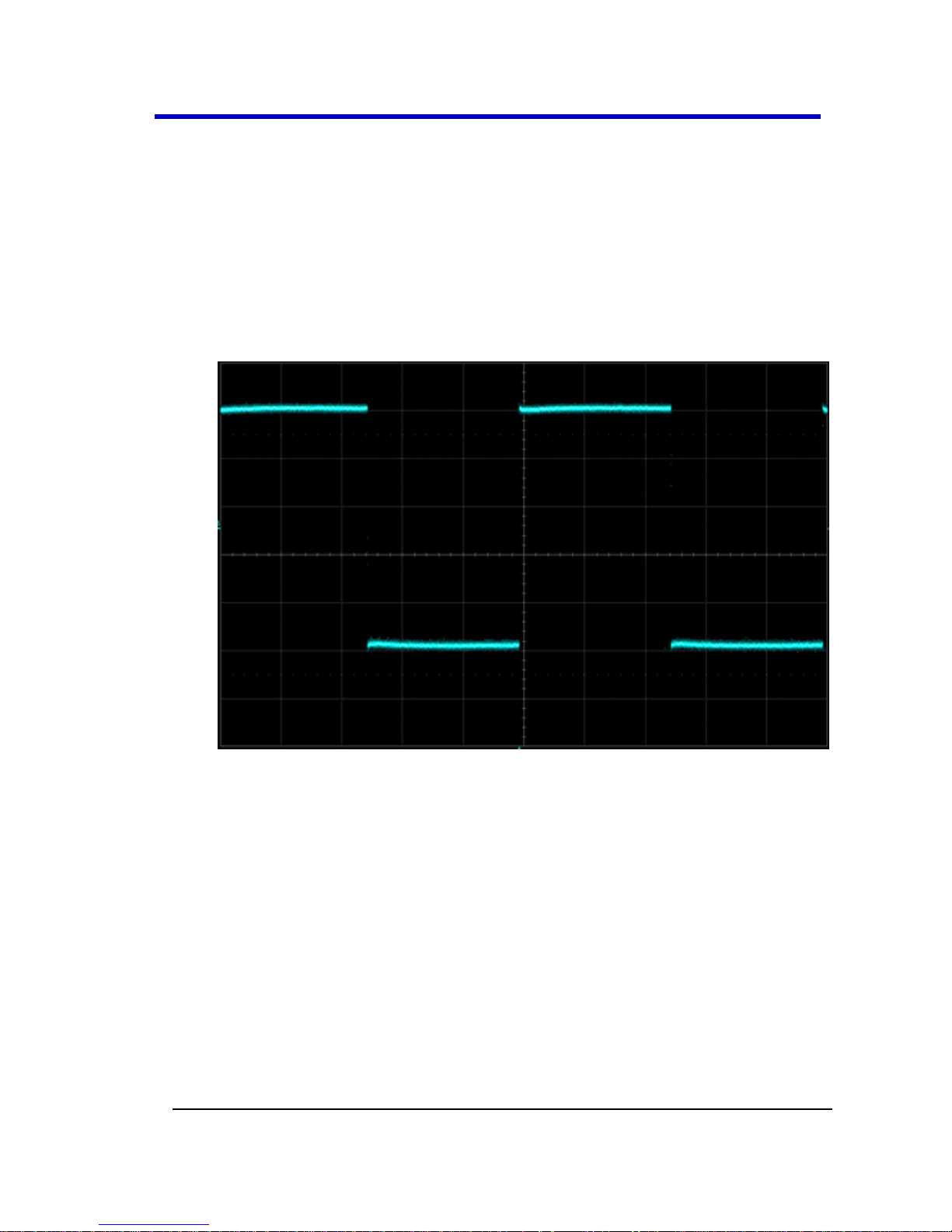
LabMaster 9 Zi-A Oscilloscopes
97
LM9Zi-A-GSM-E RevA
Passive Probe Compensation
Passive probes must be compensated to flatten overshoot. This is
accomplished by means of a trimmer at the connector end of the probe.
1. Attach the connector end of your passive probe to any channel.
2. Connect the probe end to the CAL output connector at the front of
the oscilloscope. Ground the probe.
3. Adjust the trim pot at the connector end of the probe until the
square wave is as flat as possible.
Page 98

Getting Started Manual
LM9Zi-A-GSM-E RevA
98
Display Dashboard
Display Dashboard Overview
This section covers the various aspects of the user interface shown in the
display of your instrument.
Screen Layout, Groupings, and Controls
The instrument's screen is divided into the following main sections:
Menu Bar
Signal Display Grid
Descriptor Labels
Dialog(s)
The Message Bar
Note: Many front panel controls directly correspond with screen layout
controls. For example, the Print front panel general control button
corresponds with the Hardcopy function set from Utilities → Utilities
Setup → Hardcopy.
Menu Bar
The top of the screen contains a menu bar of commonly used functions.
Whenever you touch one of these buttons and make a selection from its
drop-down menu, the dialog area at the bottom of the screen displays
the corresponding dialog.
Page 99
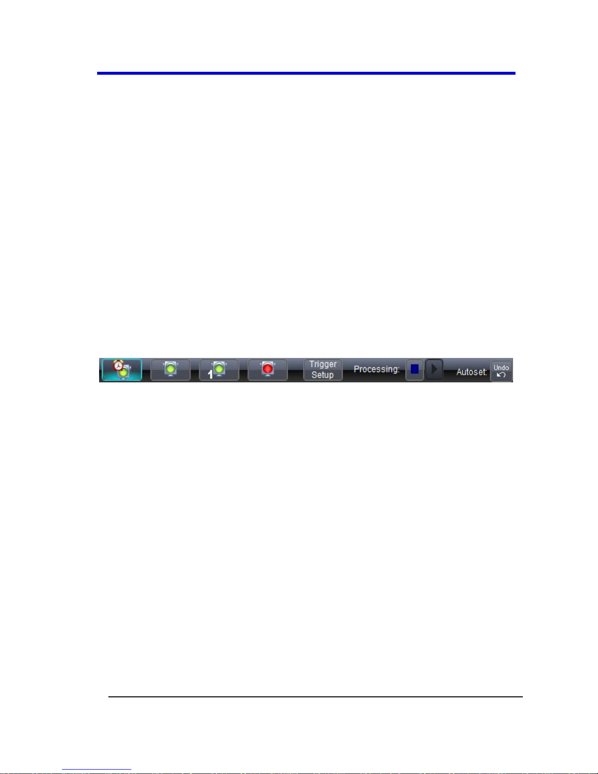
LabMaster 9 Zi-A Oscilloscopes
99
LM9Zi-A-GSM-E RevA
Specific Menu Bar functions are referenced using arrow-separated path
descriptions. For example, the Save Setup function is referenced as File
→ Save Setup....
PLEASE NOTE THE FOLLOWING:
For common oscilloscope operations, you don't need to use the top
menu bar (since you can access most dialogs from the Front Panel or
from the Descriptor Labels). However, it is the only way to access setup
or other dialogs for Display Setup, Save or Recall Waveform, Save or
Recall Setups, Print Setup, Vertical (Channel), Horizontal, or Trigger
Status, Memory (Reference Waveform) Setup, Pass/Fail Setup, or
Utilities and Preferences Setup....
The Quick Access Toolbar
The Quick Access toolbar is located on the right side of the menu bar.
You can use these toolbar buttons to quickly access Trigger, Processing
and Undo functionality.
Quick Access Trigger Functions
Auto - Press to turn on Auto Trigger mode, which triggers the
oscilloscope after a time-out, even if the trigger conditions are not
met.
Normal - Press to turn on Normal Trigger mode, which triggers the
oscilloscope each time a signal is present that meets the
conditions set for the type of trigger selected.
Single - Press to turn on Single Trigger mode for the selected
channel, which arms the oscilloscope to trigger once (single-shot
acquisition) when the input signal meets the trigger conditions set
for the type of trigger selected. If the oscilloscope is already
armed, it forces a trigger.
Stop - Press to prevent the oscilloscope from triggering on a signal.
If you boot up the instrument with the trigger in Stop mode, the
message "no trace available" is shown.
Page 100
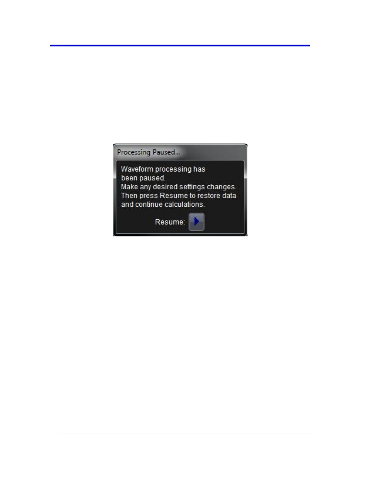
Getting Started Manual
LM9Zi-A-GSM-E RevA
100
Trigger Setup - Press to open the Trigger Setup... dialog.
Corresponds with screen menu selection: Trigger → Trigger
Setup....
Quick Access Processing Functions
The Processing section allows you to suspend your system from
processing data. You can stop data processing, make adjustments, and
then resume data processing with the touch of two on-screen buttons.
Touching the Stop button shows the Processing Paused... pop-up.
Touch the Resume button to continue processing data.
At times, an Undo button is made available to the right of the Quick
Access Toolbar on the Menu Bar.
Quick Access Undo Function
The Undo button is labeled with the most recent action (Autoset being
the most recent action in the screen-shot of the Quick Access Toolbar at
the beginning of this topic). This helps make you aware of the specific
function prior to reversal.
 Loading...