

Page 1
WaveMaster®8 Zi Series
4 GHz – 30 GHz
World’s Fastest Real-time Oscilloscope
Eye Doctor™II Advanced Signal Integrity Tools
Superior Serial Data Analysis
World’s Fastest Real-time Oscilloscope
Eye Doctor™II Advanced Signal Integrity Tools
Superior Serial Data Analysis
Page 2
2
THE NEW OSCILLOSCOPE EXPERIENCE IS HERE
World’s Highest Bandwidth
Real-time Oscilloscope with
Superior Performance
WaveMaster 8 Zi combines the
highest bandwidth and sample rate
with the superior performance of
the X-Stream™ II architecture to
maximize speed in all aspects—high
bandwidth signal capture, 10–100x
faster analysis processing, instanta-
neous instrument responsiveness,
and 20x faster off-line data transfer.
Availability of models from 4 to
30 GHz with complete bandwidth
upgradability makes it easy and
affordable to stay current with
emerging high-speed technologies
and serial data standards. In
addition, all models include both
50 Ω and 1 MΩ inputs and support
for every probe manufactured by
LeCroy without requiring external
adapters or probe amplifiers.
Combined with LeCroy’s flexible
and deep analysis toolbox, the
WaveMaster 8 Zi Series provides
an unforgettable experience for
the debugging, validation,
analysis and compliance testing
of electronic designs.
13
3
Page 3

3
1. Industry leading performance—30 GHz bandwidth,
80 GS/s sample rate, 512 Mpts of analysis memory
2. Eye Doctor™ II Advanced Signal Integrity Tools
improves signal integrity measurements with
real-time de-embedding and emulation capabilities
on full record lengths
3. Superior serial data analysis with SDA II software—
more capability to decompose and analyze jitter and
determine root cause quickly
4. X-Stream II streaming architecture—10–100 times
faster than other oscilloscopes
5. Deepest toolbox with more measurements, more
math, more power
6. Exceptional instrument responsiveness, even at
maximum acquisition memory
7. 325 MB/s data transfer rate from oscilloscope to
PC with LeCroy Serial Interface Bus (LSIB) option
8. Widest bandwidth upgrade range provides best
investment leverage
9. 15.3" widescreen (16x9) high resolution WXGA
color touch screen display—50% larger than
12.1" displays
10. TriggerScan™ detects and captures more
anomalies per second
11. Low-speed serial triggering and decode (I
2
C,
SPI, UART-RS232, CAN, LIN, FlexRay™) available
to provide a total system view
12. WaveScan™ quickly and intuitively locates,
analyzes and displays abnormal events even
in long waveforms
13. 50 Ω and 1 MΩ inputs with both ProBus and
ProLink probe interfaces on all models provide
unsurpassed flexibility
12
10
11
4
5
1
2
8
9
6
Page 4

LEADING PERFORMANCE, INNOVATIVE TECHNOLOGY
4
L
E
A
R
N
M
O
R
E
Page 5

5
L
E
A
R
N
M
O
R
E
Innovative, Superior, Upgradeable
World’s Fastest Real-time
Oscilloscope
LeCroy has broken bandwidth barriers
by combining custom designed SiGe
high-speed components with 5th
generation Digital Bandwidth Inter-
leave (DBI) technology to achieve
unprecedented real-time oscilloscope
performance:
• 30 GHz
• 80 GS/s
• 512 Mpts/Ch Analysis Memory
Most Advanced Oscilloscope
Platform
X-Stream II architecture provides
10–100x faster processing of long
records, true 512 Mpts analysis
memory, and instantaneous instru-
ment responsiveness. When off-line
data analysis is preferred, the LeCroy
Serial Interface Bus (LSIB) provides
up to 325 MB/s data transfer speeds.
A 15.3" WXGA touchscreen display
provides 50% more viewing area
compared to other oscilloscopes
in this class. Both 50 Ω and 1 MΩ
inputs are standard on all oscilloscopes,
as is support for all LeCroy probes
(including passive probes) without the
need for easy to lose external adapters
or expensive power supplies.
Eye DoctorTMII Advanced
Signal Integrity Tools Add
Measurement Precision
LeCroy’s Eye Doctor II Advanced
Signal Integrity Tools add precision
to signal integrity measurements
by allowing the subtraction of fixture
effects, and the emulation of empha-
sis, serial data channels, and receiver
DFE, FFE, and CTLE equalization
effects while at the same time main-
taining fast oscilloscope processing
speed on unlimited record lengths.
This allows the engineer to re-capture
design margin, better understand
actual circuit performance, and per-
form compliance testing on emerging
high-speed standards, such as PCIe
Gen3, USB 3.0, SAS/SATA 6 Gb/s,
that require emulation to ensure high
field reliability and interoperability.
Superior Serial Data Analysis
SDA II Serial Data Analysis Software
provides the highest confidence for
serial data testing. Eye diagram analysis
provides 100x faster capture of unit
intervals (UI) in the eye diagram, and
is enhanced with superior eye diagram
analysis tools, such as lines of
constant bit error rate (IsoBER ) and
mask violation locators. Superior jitter
decomposition methodologies and
analysis tools provides more ability to
understand problem behaviors in serial
data systems. X-Stream II architecture
leverages the superior tools through
10–100x faster processing and com-
plete analysis processing of full record
lengths, providing more insight faster.
World’s Fastest Single-Chip ADC
Monolithic, custom designed Silicon
Germanium (SiGe) 40 GS/s Analog-to-Digital
Converter (ADC) is the world's fastest single-chip ADC.
Page 6

THE BEST HIGH BANDWIDTH INVESTMENT
As memory and sample rate can be
interleaved, so can bandwidth. Using high-
performance microwave and RF technolo-
gies, and high-speed processors and
digital signal processing (DSP), LeCroy
intelligently operates high-speed analog
components comfortably within their
rated bandwidth range while providing
twice the four channel bandwidth on
two channels. This approach offers
better signal fidelity compared to
“stretching” of components beyond
their rated bandwidth.
Silicon Germanium (SiGe)
technology is deployed with
IBMs 7HP process to create
specialized analog-to-digital
converters (ADCs), and
track/holds. There is one
ADC and one track and
hold per acquisition channel,
located in close proximity to
maintain good signal fidelity
and optimal response.
The layout path is precisely
controlled to maintain
high signal fidelity for
each channel.
5th Generation Digital Bandwidth Interleave (DBI)
Custom Designed to Ensure High-performance
Learn More
http://www.lecroy.com/tm/Library/White
Papers/PDF/DBI_Explained.pdf
6
Page 7
7
From the perspective of bandwidth, sample rate,
processing speed, responsiveness, display size, and
range of capability, the WaveMaster 8 Zi platform is
clearly superior and will remain so for many years to
come. With the widest bandwidth upgrade range, an
engineer who is working on 2nd generation technologies
today can confidently know that WaveMaster 8 Zi will
support 3rd or 4th generation technology needs several
years from now.
Widest Bandwidth Upgrade Range: 4–30 GHz
Best Investment Protection
All WaveMaster 8 Zi oscilloscopes are implemented with a single hardware platform. To extend bandwidth beyond
16 GHz, LeCroy has leveraged DBI technology to minimize initial costs—the RF deck that doubles the bandwidth is
a separate module that slides into a slot in the WaveMaster 8 Zi platform.
World’s Fastest Single-chip ADC
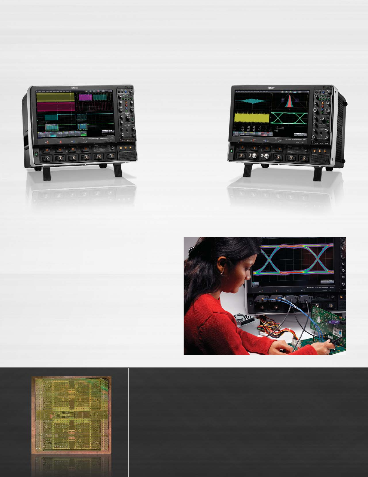
WaveMaster 816Zi
SDA 830Zi
The monolithic 40 GS/s ADC
is the fastest single-chip
ADC. Compared to other
approaches that use multi-
ple ADC chips per channel,
or single-chip ADCs with
more than 100 interleaved
converters, the LeCroy
approach is a simpler
more elegant solution for
Page 8

8
As signal speeds and data rates
have increased into the microwave
frequency range, engineers have had
to face new challenges with signal
integrity measurements. Eye Doctor II
is a complete set of tools that adds
precision to signal integrity measure-
ments by permitting de-embedding
and emulation (emphasis or receiver
equalization) on full record lengths (up
to 512 Mpts). By using Eye Doctor II,
the engineer can eliminate the impact
of unwanted devices, and design
margin is recaptured. Eye Doctor II
uses industry-standard S-parameter
measurements and Touchstone
files that are easily uploaded into
Eye Doctor II. All basic capability
is easily accessible a streamlined,
simple user interface. More advanced
capability is accessible in through the
Processing Web Editor. The complete
LeCroy analysis toolbox, such as
parameters, math functions, jitter
tracks, histograms, eye diagrams,
etc., may be further applied to any
Eye Doctor II processed signal.
Eye Doctor II Advanced Signal Integrity Tools
High-speed Memory
Test Fixture and Cable
De-embedding
Even high quality test fixtures and
cables have a negative impact on
signal quality that increases dispropor-
tionally with higher signal frequency. If
the test fixtures and cables can be elec-
trically quantified in terms of S-parame-
ters or attenuation factors, they can be
removed from the measurement result.
Emphasis Emulation
Serial data channels have a dispropor-
tionate impact on the high frequency
content of the serial data signal. There-
fore, transmitter designers sometime
employ the use of emphasis to pre-
compensate for these effects. Either
de-emphasis or pre-emphasis can be
added or removed from a serial data
signal with Eye Doctor II.
Serial data signal probed
at the transmitter output
shows acceptable response
The receiver usually applies
equalization to “open” the
eye. This equalization can
be modeled to show how
the signal appears to the
receiver after equalization
is applied
Losses in the serial data
channel affect the signal
integrity. This effect can be
de-embedded or emulated
Custom high-speed memory
chips on multiple memory
plug-in cards achieve up to
256 Mpts/channel (or up
maintaining proper timing,
phasing, and offset be-
tween the on-chip ADCs.
Page 9

Add Precision to Signal Integrity Measurements
Serial Data Channel
Emulation
When measuring serial datastreams,
there are additional considerations.
Most commonly, but not always, a
design engineer will measure the
serial data signal at the output of the
transmitter. Therefore, it is commonly
desired to emulate the serial data
channel after the transmitter output.
Some emerging high-speed standards,
such as SuperSpeed USB or PCIe
Gen3, require various test conditions
to emulate a variety of serial data
channels to ensure field reliability
and interoperability.
It may also be desired to “virtually
probe” the serial data signal in
your circuit using a combination
of de-embedding and emulation
to allow a view of the signal anywhere
in your circuit, regardless of whether
you can actually probe there or not.
Eye Doctor II makes this possible.
Receiver Equalization
Serial data receivers often incorporate
equalization to compensate for the
impact of the serial data signal as
transmitted over the serial data
channel and input to the receiver.
Thus, it is possible for a “closed-eye”
serial data signal input at the receiver
to be equalized by the receiver and
result a properly decoded signal. Eye
Doctor II provides the ability to apply
Feed Forward Equalization (FFE),
Decision Feedback Equalization (DFE)
or Continuous Time Linear Equalization
(CTLE) and replicate or model the
receiver equalization.
This would provide ability to view
eye diagram and jitter performance
on the signal as it is actually present
at the receiver even though there
was no way to access or probe the
signal at the location of interest.
Open eye with 2.5 Gb/s serial data signal.
At this data rate, the probed signal is mostly
unaffected by serial data channel response.
As the serial data rate increases, the
attenuation in the backplane “closes” the
eye diagram at the input to the receiver.
By using Eye Doctor II to apply serial data
channel emulation to correct for backplane
emulation, then using Eye Doctor to apply
receiver equalization to mimic functionality
of the hardware receiver, we can understand
whether the signal as received by the
receiver has acceptable jitter performance
or not.
9
to 512 Mpts/Ch interleaved
with some models and
options). X-Stream II
architecture ensures fast
and complete processing
of full record lengths
with no limitations on
analysis memory.
Page 10

X-STREAM II FAST ANALYSIS AND RESPONSIVENESS
Deep Insight
for Analysis
Applying the WaveMaster
8 Zi Series’ flexible and
deep measurement
and analysis toolbox to
characterize and validate
a design creates under-
standing. That is Deep
Insight. An oscilloscope’s
operating performance
comes from the design
that integrates the operat-
ing system, the hardware
processor and the wave-
form processing method.
Each component is impor-
tant to the overall architec-
ture performance but only
the X-Stream II waveform
processing method un-
leashes amazing speed
performance and no
compromise in responsive-
ness, thus drastically reduc-
ing the time to generate
Deep Insight.
10
Page 11

LeCroy – The Analysis
Memory Leader
LeCroy has found a way to make
long acquisition memory seamless
and pain free to use. The WaveMaster
8 Zi Series’ proprietary X-Stream II
architecture supports capturing, zoom-
ing, measuring and analyzing multiple
waveforms at up to 512 Mpts deep.
WaveMaster 8 Zi’s proprietary architec-
ture design is augmented with an
Intel®Core™ 2 Quad processor,
high-speed serial data buses, a 64-bit
OS and up to 8 GB of RAM. What
you experience is a processing
speed 10–100x faster compared
to other oscilloscopes in this class.
Instantaneous Responsiveness
The first time you use the WaveMaster
8 Zi oscilloscope you will experience
remarkable responsiveness. Acquiring
and manipulating the longest record
lengths and performing the most
complex WaveShape Analysis are
all easily handled at the same time.
No time is lost waiting for one
operation to end or the next one
to begin. Unlike competitive oscillo-
scopes that become painfully slow
to respond when long memory
is applied. Bottom line: oscilloscopes
no longer need to carry a penalty for
operating with long memory.
Fast Off-Line Data Transfer
When the application calls for post-
processing data off-line, an optional
LeCroy Serial Interface Bus (LSIB)
high-speed 325 MB/s option provides
data transfer 20–100x faster than any
other test instrument.
LXI Class C Compliance
WaveMaster 8 Zi is Class C compliant
with the LXI standard, the latest
industry standard for Ethernet remote
control operation. WaveMaster 8 Zi
supports standard LXI features such
as a LAN interface, VXI11 Discovery,
a web server and IVI-C & IVI-COM
drivers. The LXI interface allows
engineers to build powerful, web-
enabled test systems in less time.
WaveMaster 8 Zi excels at performing complex calculations on long waveforms,
enabling users to gain waveform insight with confidence. Here, a 40 Mpts PCIe Gen1
waveform acquisition is acquired and fully analyzed in a matter of seconds—nearly
100x faster than competitive oscilloscopes.
11
X-Stream II Architecture
Optimized for Fast Throughput
X-Stream II architecture enables high
throughput of data—even when the
oscilloscope is performing multiple
100 Mpts (or larger) waveforms. X-Stream
II uses variable waveform segment
lengths to enable all processing intensive
calculations to take place in fast CPU
cache memory, thus improving calculation
speed and efficiency. The result—10–100x
faster processing compared to other
oscilloscopes.
Optimized for Long Memory
X-Stream II essentially has no analysis
memory length restrictions, regardless
of analysis type, since the variable
waveform segment length can always
be limited to a size that can fit in CPU
cache memory. Other oscilloscopes
with conventional architectures cannot
make this claim, and often have limitations
on analysis memory of 5–20% the length
of their acquisition memory under the
best conditions.
Optimized for Responsiveness
By dynamically allocating buffers to
maximize memory availability, the
WaveMaster 8 Zi Series embodies
the fastest front panel responsiveness.
A built-in processing abort makes front
panel control changes instant by stopping
the current process and allowing new
waveforms to be positioned or zoomed—
all without a lengthy recalculation.
Meanwhile, waveform previewing shows
interim calculation results.
Page 12

1212
MOST COMPLETE DEBUG SOLUTION FROM 4–30 GHz
Quick Insight for Debug
Insight
is the power or act of seeing into a
situation. Start up problems on a new design
require a combination of problem recognition,
precise triggering for fast isolation of rare
events, and comparison tools that help corre-
late timing of problems. The ability to capture
megapoints of waveform information and
intuitively analyze it to find anomalies shortens
the time to debug. WaveMaster’s TriggerScan,
WaveScan and deep measurement toolbox
maximize quick insight.
High bandwidth differential probes,
single-ended active probes,
current probes, high-voltage,
and mixed signals all connect
to the WaveMaster 8 Zi oscilloscope
and give you a total system view.
Page 13

1313
Freedom from Probing
Limitations
WaveMaster 8 Zi excels in the way
it offers general purpose utility never
before seen in oscilloscopes from
4 to 30 GHz. All WaveMaster 8 Zi
oscilloscopes contain selectable
50 Ω and 1 MΩ input capability and
can be used with any LeCroy probe—
passive or active—without requiring
external adapters or power supplies.
Use the two inputs per channel as a
built-in switch matrix.
Complete System Debug
Understanding the relationships
between different signals is vital to
fast debug. Only WaveMaster 8 Zi
combines the best of general purpose
oscilloscopes (low-speed serial
triggers and decoders, mixed signal
capability, high impedance probing)
with specialized 50 Ω inputs. This
provides ability to 100% correlate
high bandwidth signal activities or
problems to low-speed events, such
as low-speed serial data control
words, power supply noise, or parallel
data transmissions.
A New Way to Control
an Oscilloscope
WaveMaster’s fast and responsive
front panel and touch screen user
interface are well integrated so you
can easily choose and setup your
vertical, horizontal trigger and meas-
urements. Zoom and scroll through
a long waveform signal, control the
oscilloscope with the detachable
front panel right next to the circuit
being probed.
Page 14
14
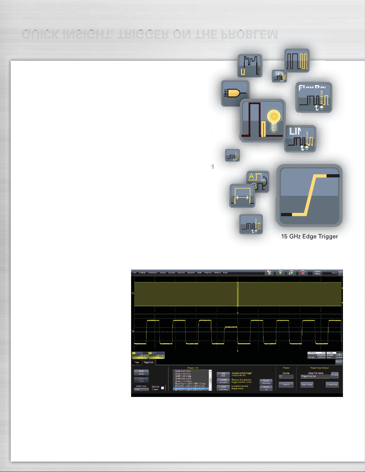
QUICK INSIGHT: TRIGGER ON THE PROBLEM
A
B
LIN
FlexRay
More Triggers Isolate More Problems More Effectively
A powerful combination of a 15 GHz Edge trigger, 10 different
SMART triggers, and Cascade™ triggering allow you to isolate the
problem quickly and begin to focus on the cause. Some SMART triggers
allow triggering on pulse widths or features as small as 200 ps. Cascade
triggering enables any three triggers to be combined in an A then B
then C cascaded condition. A high-speed serial trigger enables triggering
on up to 3.125 Gb/s serial patterns of up to 80-bits in length. Built-in
hardware clock recovery is also included.
A full range of serial triggers (I
2
C, SPI, UART, RS-232, CAN, LIN, FlexRay)
are available, providing capability to isolate events related to serial
peripheral bus traffic. Most serial triggers contain powerful conditional
DATA triggering to allow inclusion or exclusion of entire ranges of data
values, which expedites understanding of how a range of serial bus
traffic DATA values interact with other signals.
TriggerScan
™
TriggerScan uses high-speed hardware triggering capability with persistence
displays to capture only the signals of interest and provide answers up to
100x faster than other methods. Traditional fast display update modes work
best on frequent events occurring on
slow edge rates while TriggerScan
deploys trigger hardware to find
infrequent events on fast edge rates.
A built-in automated Trigger Trainer
analyzes the waveforms, identifies
normal behavior, and then sets up a
large set of rare event smart trigger
setups that target abnormal behavior.
The trainer ‘learns’ trigger setups to
identify faulty operation based on
slew rates, periods, amplitudes, etc.
outside of a range and then applies
them sequentially. It then rapidly
sequences through each individual
trigger with a user-defined dwell
time, and captures and displays any
anomalous signals that meet the
trigger conditions.
SPI
UART
A 1 in a billion rare event seems fast but is only 5 seconds of circuit operation on a
200 MHz clock. TriggerScan finds the rare event in 4 minutes while an oscilloscope
with 400,000 waveforms/second capture rate misses 99.8% of the signals and could
spend nearly 42 minutes to find the error.
15 GHz Edge Trigger
I2C
Page 15

QUICK INSIGHT: SEARCH AND SCAN TO UNDERSTAND
Fully Integrated Mixed Signal Oscilloscope (4+36) Option
15
Add Mixed Signal Oscilloscope (MSO)
operation using the MS Series mixed signal
options. These convenient add-ons connect
to the LeCroy LBUS and quickly and simply
provide capability to acquire up to 36 digital
lines time-correlated with analog waveforms. No time is wasted in trying to learn
how to connect, synchronize or operate a
complicated logic analyzer since the MSOs
are already completely integrated
with the scope operation. In
addition to acquiring digital lines,
they are also helpful for monitoring low-speed signals, such as
serial data clock, data, and chip
select signals, thus preserving
the analog channels for higher
speed requirements.
WaveScan™Advanced Search
and Analysis Finds Problems
that Triggers Won’t Find
The best trigger won’t find all unusual
events—a more powerful capability
is sometimes needed. WaveScan
provides the ability to locate unusual
events in a single capture (i.e., capture
and search) or “scan” for an event
in many acquisitions over a long
period of time. Select from more
than 20 search modes (frequency,
rise time, runt, duty cycle, etc.), apply
a search condition and begin scanning.
When an event is found, WaveScan
highlights the error on screen and
displays a table listing the errors.
Simply click on an event in the table
and go right to the anomaly. The
X-Stream II processing architecture
quickly ‘scans’ millions of events
much faster than any other oscillo-
scope. Individual events can be
compared and contrasted using
ScanHisto and ScanOverlay features.
These tools simplify the understanding
of how errors correlate across input
channels thus enabling faster debug.
Serial Decode—A Whole
New Meaning to Insight
Advanced software algorithms
deconstruct serial data waveforms
into binary, hex, or ASCII protocol
information and then overlay the
decoded data on the waveform.
Each section of the protocol is
uniquely color-coded to make
it easy to understand. The
decode operation is fast—even
with long acquisitions. Turn
your oscilloscope into a
protocol analyzer with the Table
Display of protocol information.
Customize the table, or export table
data to an Excel file. Select a table
entry and automatically zoom for
detail. Search for specific address
or data values in the acquisition.
Supported serial standards are 8b/10b,
PCIe, PCIe 2.0, SAS, SATA, XAUI,
I
2
C, SPI CAN, LIN, UART-RS-232,
and FlexRay.
Find over 20 different types of features with WaveScan. Each feature is highlighted in
the waveform and listed in a table. From the Scan Table jump directly to any anomaly
and overlay for characterization.
MSO options add capability to incorporate both
analog and digital signals into a 4+36 pattern trigger
for useful debugging in mixed signal designs.
Page 16

All Oscilloscope Tools
are not Created Equal
WaveMaster 8 Zi has the
deepest toolbox of any
oscilloscope, providing
more measure, math,
graphing, statistical, and
other tools, and more ways
to leverage the tools to get
the answer faster. While many
other oscilloscopes provide
similar looking tools, LeCroy
allows the most flexibility in
applying the tools to any
waveform—whether it be a
math or graphing function,
memory trace, FFT, or parameters.
Tools can be chained together
to create unique views and
understanding. All tools supplied
with optional application pack-
ages are always integrated into
the general purpose oscilloscope.
DEEP INSIGHT TO CLARIFY COMPLEX SIGNALS
More Ways to Analyze
Convert time-domain information
into statistical, parameter, or
frequency domain. Use the
oscilloscope as a spectrum analyzer
for detailed frequency analysis
(WM8Zi-SPECTRUM option).
Implement Finite or Infinite Impulse
Response (FIR or IIR) filters to
eliminate undesired spectral compo-
nents and enhance your ability
to examine important waveform
components (WM8Zi-DFP2 option).
More Ways to Create
Only LeCroy completely integrates
third party programs into the scope’s
processing stream by allowing you
to create and deploy a new measure-
ment or math algorithm directly into
the oscilloscope environment and
display the result on the oscilloscope
in real-time! There is no need to
run a separate program, or ever leave
the oscilloscope window. With the
WM8Zi-XDEV Advanced Customiza-
tion package, you can extend your
WaveMaster 8 Zi
to include your most
unique algorithms
using FastWave port
based on C/C++,
and other programs
(MATLAB, Excel,
Jscript (JAVA), and
Visual Basic). The
code is entered in
real time using the
oscilloscope menus,
which allows the
built-in debugger to
provide immediate
feedback. The result-
ing measurement or
math waveform is
then returned to the
display, allowing
further analysis within
the oscilloscope.
X-Stream II fast throughput streaming architecture makes
difficult analysis and deep insight possible. Above, an FFT
is applied to a 50 Mpts waveform to determine root cause
failure. The high frequency resolution this provides enables
deep insight into signal pathologies.
XDEV allows MATLAB
®
script to apply a customized filter
and return the waveform to the scope display. Continue
further analysis with the advanced toolbox in the oscilloscope.
16
Page 17

DISPLAY OPTIMIZED FOR ANALYSIS
More Ways to Understand
Use the processing web to set
up advanced math operations.
Apply multiple operators and
process large amounts of data
simultaneously to achieve the
deepest of insights. Overlay color-
coded protocol decodes to serial
datastreams for fast understanding.
Track Views
Track in WaveMaster 8 Zi (WM8Zi-
JTA2 option) uses every instance of
a measurement in an acquisition to
create a plot of measurement values
on the Y-axis and time on the X-axis.
The result is a graphical display of a
measurement change time-correlated
to the original channel acquisition—
perfect for intuitive understanding
of behaviors in frequency modulated
(FM) or pulse width modulated (PWM)
circuits and jitter measurements,
including modulation or spikes.
Histograms
WaveMaster 8 Zi calculates over
750,000 measurements/second—5x
faster than other oscilloscopes in its
class. With this much data, it is essen-
tial to provide more than just a list of
mean, min, max, sdev, etc. values.
Histograms provide an intuitive
way to graphically view the distribu-
tion of statistical data and quantify real
insight into underlying problems.
Trend Views
Slowly sample at 1000 seconds/div
to capture hours of slow-speed
signal data and turn your oscilloscope
into a strip chart Recorder. Using
Trend views, plot measurement
values of high-speed signals with
slower speed signals, such as
transducer or voltage values.
Capture 5 ms (100 Mpts) of low-speed and high-speed waveforms. Easily zoom, and
validate timing relationships between signals.
Data Transfer Speeds
25–100x Faster
LeCroy’s Serial Interface Bus (LSIB)
option enables direct connection to
the PCI Express®x4 high-speed
data bus in the oscilloscope to enable
data transfer rates up to 325 MB/s.
All that is required is installation of an
optional LSIB card in the oscilloscope
and the corresponding host board
(card) for desktop (laptop) PC in the
remote computer. Data transfer is
easily enabled through a supplied
application program interface (API).
17
Data Transfer Speeds
Page 18

TRIPLE THE DISPLAY AREA, ACHIEVE GREATER INSIGHT
The integrated second
touchscreen display
is used to display
simultaneous view
of serial data jitter
using eye diagrams
for total jitter and
jitter decomposition
analysis views.
Thus, it is possible
for a design engineer
to quickly understand
system behavior and
root cause of high
serial data jitter.
18
Page 19
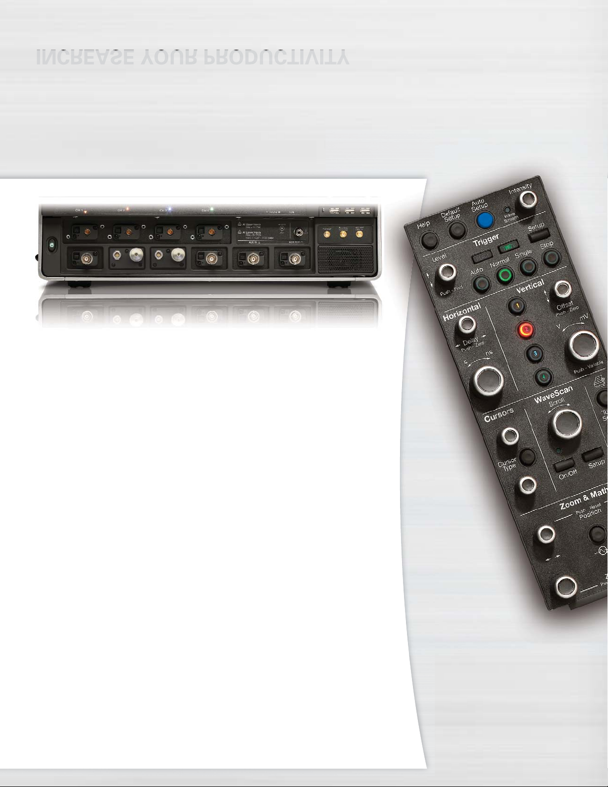
INCREASE YOUR PRODUCTIVITY
The front panel on
the WaveMaster 8 Zi
is removable. This
allows you to put the
front panel next to the
circuit under test, or locate
it remotely from the test area.
Simply connect a standard USB 2.0
cable of any length to the front
panel and untether yourself from
standard oscilloscope constraints.
Second Display Quickens
Time to Insight
The optional integrated second 15.3"
WXGA touchscreen display offers
creative new ways to display multiple
waveforms, third party software, the
graphical LeCroy Processing Web,
or on-line Help. Grids can be split
between displays, and waveforms
can easily move from the upper to
lower display to show more useful
analysis information and quicken the
time to insight. With the second
display, the total grid display area
is three times that of the 12.1"
displays commonly used on other
oscilloscopes in this class.
Input Full Range of High
Bandwidth and Low
Bandwidth Signals
High bandwidth oscilloscopes require
special connectors, such as SMA or
K-type/2.92 mm. Other oscilloscope
suppliers provide these and no other
types, which limits high bandwidth
oscilloscopes to specialized measure-
ment of high bandwidth signals only.
However, LeCroy also provides
inputs with BNC connectors and
1 MΩ input impedance for use with
standard passive probes. These
same connectors are also usable
with LeCroy’s full line of high imped-
ance active single-ended probes,
low bandwidth differential probes,
current probes, high voltage probes,
etc. Thus, a customer can input the
full range of high bandwidth (e.g.
serial data) and low bandwidth (e.g.
power supply, low-speed serial data
I2C, SPI, etc.) signals into any band-
width WaveMaster 8 Zi oscilloscope,
eliminating the need for costly special
adapters or auxiliary probe power
supplies, or additional general purpose
oscilloscopes, and allowing the widest
range of signal types to be input into
the oscilloscope.
19
The 8 inputs can essentially be multiplexed into four channels to minimize probe
reconnections or to simplify automated testing.
Page 20

20
APPLICATION SPECIFIC SOLUTIONS
In addition to the general
purpose WaveShape
Analysis tools, application
specific solutions are
available for Serial Data
Compliance, Embedded
Design, Digital Design, and
Automotive. These packages
extend the LeCroy standard
measurement and analysis
capabilities and expand
your oscilloscope’s utility
as your needs change.
I2C decoding package with intuitive color decoding and table view allows quick
location of 0x42 address.
Digital Filter Software
Package (WM8Zi-DFP2)
DFP2 lets you implement Finite or
Infinite Impulse Response filters
to eliminate undesired spectral
components, such as noise, and
enhances your ability to examine
important signal components. You
can choose from a standard set
of FIR or IIR filters. You can also
design your own filters.
Spectrum Analyzer Analysis
Package (WM8Zi-SPECTRUM)
SPECTRUM converts the controls of
your oscilloscope to those of a spec-
trum analyzer. Adjust the frequency
span, resolution and center frequency.
Apply filtering to your signal and watch
the frequency signature change in real
time. A unique peak search labels
spectral components and presents
frequency and level in a table. Touch
any line to move to that peak.
Serial Data Trigger and Decode
Quickly and easily isolate serial data events on your embedded controller for better
understanding and faster debug. Trigger and decode options provide powerful
conditional triggering, intuitive color-coded decode overlays, and a table summary
with search and zoom capabilities. Decode solutions are available for PCIe, PCIe
2.0, SAS, SATA, XAUI, generic 8b/10b, or user-defined 8b/10b format. Trigger and
decode solutions are available for I
2
C, SPI, UART/RS-232, CAN, LIN, and FlexRay.
Page 21

Serial Data Compliance
Packages
QualiPHY serial data compliance packages provide easy to use step-by-step
instructions for a broad set of serial data standards, such as Ethernet, USB 2.0,
PCI Express, SATA, HDMI, DisplayPort and UWB (Ultra-Wideband). With fast
automated perform-
ance, illustrated
instructions and com-
prehensive reporting
capability, QualiPHY
packages are the
best solution for com-
pliance testing. For
standards not sup-
ported with QualiPHY
compliance packages,
jitter and eye diagram
test toolsets are
generally included in
the SDA 8 Zi models.
21
Mixed Signal Oscilloscope
Option (MS-250/MS-500)
The Mixed Signal options allow the
WaveMaster 8 Zi to convert to a
mixed signal oscilloscope with up
to 36 digital channels. Channels are
sampled at 2 GS/s (500 MHz max
clock speed) up to 50 Mpts/Ch.
Having up to 36 digital inputs time-
synchronized with four analog
channels extends the oscilloscope's
use to provide a total system view.
Jitter and Timing Analysis
Package (WM8Zi-JTA2)
JTA2 Specialized timing parameters
measure period, cycle-cycle, half
period, width, etc. jitter on a variety
of signals. Use the three views of
jitter (statistical, time, and frequency)
to understand root cause and to
debug problems. Histograms provide
understanding of statistical distribu-
tions. Tracks provide a means to
show time-correlated peaks of jitter,
and compare to other signals. FFTs
provide the ability to debug root
causes of high in-circuit jitter.
Eye Doctor II – Advanced
Signal Integrity Tools
(WM8Zi-EYEDRII)
Eye Doctor II Signal Integrity Tools
provide the ability to add precision
to signal integrity measurements by
allowing subtraction of fixture effects
and emulation of emphasis, serial
data channels and receiver Decision
Feedback Equalization (DFE) Forward
Feedback Equalization (FFE) and
Continuous Time Linear Equalization
(CTLE) effects while at the same time
maintaining fast scope update speed
on unlimited record lengths.
Using Eye Doctor II, an engineer
can re-capture design margin that
was previously sacrificed to the test
fixtures and cables and better under-
stand actual circuit performance.
Page 22

22
SDA 8 Zi SERIES
• LeCroy’s unique summary
view displays the Eye
Pattern, TIE, Bathtub Curve
and Jitter Histogram all on
the screen at the same time
• Create Eye Patterns utilizing
the full memory for maximum
statistical significance
• 100 times faster Eye Diagram
creation
• Gain insight with IsoBER and
Mask Violation Locator tools
• Complete Data Dependent
Jitter (DDj) decomposition with
histograms, plots, and InterSymbol Interference (ISI)
parameters and plots
• Complete Random Jitter (Rj)
+ Bounded Uncorrelated Jitter
(BUj) views include Histogram,
Spectrum and Track
• Complete Period Jitter (Pj)
analysis with a time domain
view of Pj (Pj Inverse FFT)
• Two simultaneously calculated
jitter decomposition models
provide maximum confidence
and correlation
• Trigger on 80-bit patterns
at up to 3.125 Gb/s using
the Serial Trigger
• Decode 8b/10b data on
up to 4 lanes simultaneously
• Configure the software
PLL for any standard or
custom requirement
A Total Solution for Serial Data Analysis
Unleash the power of serial data
analysis for understanding and
characterizing your design, proving
compliance and understanding why
a device or host fails compliance.
The Quad Summary View of the
SDA II software always shows the
eye, TIE, bathtub curve and jitter
histogram. No other Serial Data
Analyzer lets you see the simultane-
ous interaction and real-time changes
in all four views. The X-Stream II
Architecture provides fast updates
and the fastest eye interpretation.
Combined with up to 512 Mpts record
lengths and more complete jitter
decomposition tools, SDA II provides
the fastest and most complete under-
standing of why serial data fails a
compliance test.
Whether debugging eye pattern or
other compliance test failures, the
SDA 8 Zi Series rapidly isolates the
source of the problem in your design.
Advanced jitter decomposition
methodologies and tools provide more
information about root cause. Eye
Doctor II Advanced Signal Integrity
Tools provide more measurement
precision through the use of de-em-
bedding and emulation of cables,
fixtures, emphasis, serial data
channels, and receivers. All jitter
decomposition analysis functions
can be zoomed and time correlated
to specific serial data or other events,
making root cause determination
faster and easier.
Key Features
Page 23

A TOTAL SOLUTION FOR SERIAL DATA ANALYSIS
Automated Compliance
Testing
The QualiPHY compliance test
suite provides step-by-step
instructions for testing compliance
on a wide array of serial data
standards. The process is simplified
with fast, automated test operations,
illustrated instructions, connection
diagrams, and stop on fail feature.
Complete test reporting is also
provided.
Data Rate Configuration Chart
Minimum Recommended
Standard Bit Rate Bandwidth Oscilloscope
Serial Rapid I/O 0.5 Gb/s 13 GHz SDA 813Zi or Above
ExpressCard 2.5 Gb/s 8 GHz SDA 808Zi or Above
InfiniBand 2.5 Gb/s 8 GHz SDA 808Zi or Above
PCI Express Rev. 2.0 2.5 Gb/s 8 GHz SDA 808Zi or Above
Serial Rapid I/O 2.5 Gb/s 8 GHz SDA 808Zi or Above
DisplayPort 1.1 2.7 Gb/s 8 GHz SDA 808Zi or Above
HyperTransport 2.0 2.8 Gb/s 7 GHz SDA 808Zi or Above
SAS G2 3 Gb/s 8 GHz SDA 808Zi or Above
SATA 1.0 Gen2i 3 Gb/s 8 GHz SDA 808Zi or Above
SATA 1.0 Gen2m 3 Gb/s 8 GHz SDA 808Zi or Above
SATA 1.0 Gen2x 3 Gb/s 8 GHz SDA 808Zi or Above
Serial Rapid I/O 3.125 Gb/s 8 GHz SDA 808Zi or Above
SGMII 3.125 Gb/s 8 GHz SDA 808Zi or Above
XAUI 3.125 Gb/s 8 GHz SDA 808Zi or Above
FB-DIMM 3.2 Gb/s 8 GHz SDA 808Zi or Above
FireWire 3.2 Gb/s 8 GHz SDA 808Zi or Above
HDMI 1.3a/b/c 3.4 Gb/s 10 GHz SDA 813Zi or Above
FB-DIMM 4 Gb/s 10 GHz SDA 813Zi or Above
Fibre Channel 4GFC 4.25 Gb/s 13 GHz SDA 813Zi or Above
Serial Rapid I/O 4.25 Gb/s 13 GHz SDA 813Zi or Above
FB-DIMM 4.8 Gb/s 12 GHz SDA 813Zi or Above
USB 3.0 5 Gb/s 12 GHz SDA 813Zi or Above
InfiniBand 5 Gb/s 13 GHz SDA 813Zi or Above
PCI Express Rev. 2.0 5 Gb/s 13 GHz SDA 813Zi or Above
Serial Rapid I/O 5 Gb/s 13 GHz SDA 813Zi or Above
HyperTransport 3.0 5.2 Gb/s 13 GHz SDA 813Zi or Above
DisplayPort 1.2 5.4 Gb/s 16 GHz SDA 816Zi or Above
GDDR5 6 Gb/s 16 GHz SDA 816Zi or Above
SAS G3 6 Gb/s 16 GHz SDA 816Zi or Above
SATA Gen3i 6 Gb/s 16 GHz SDA 816Zi or Above
Serial Rapid I/O 6.25 Gb/s 16 GHz SDA 816Zi or Above
FB-DIMM 6.4 Gb/s 16 GHz SDA 816Zi or Above
HyperTransport 3.1 6.4 Gb/s 16 GHz SDA 816Zi or Above
QPI
(Quick Path Interconnect) 6.4 Gb/s 16 GHz SDA 816Zi or Above
FB-DIMM 8 Gb/s 20 GHz SDA 820Zi or Above
PCI Express Gen3 8 Gb/s 20 GHz SDA 820Zi or Above
General 10 Gb/s 25 GHz SDA 825Zi or Above
Serial Rapid I/O 10 Gb/s 25 GHz SDA 825Zi or Above
General 12 Gb/s 30 GHz SDA 830Zi
Page 24

Jitter Spectrum
• The jitter spectrum plot allows viewing
of any periodic jitter
• Peak annotation displays the frequencies
directly on the spectrum
• The LeCroy spectrum plot allows viewing of
DDj removal for maximum comprehension
Jitter Trend
• Time domain view of jitter shows transient
jitter events that can be missed by viewing
the histogram alone
• The jitter trend clearly shows any non-stationary
jitter behavior
24
Serial Trigger
The SDA 8 Zi Series comes standard
with the 80-bit Pattern Trigger installed.
The serial trigger operates up to
3.125 Gb/s and supports both 8b/10b
and NRZ signals, and also includes a
recovered clock and data output on
the front of the oscilloscope.
Flow Diagram User Interface
Eye and jitter analysis in the SDA 8 Zi
begins with a simple, interactive flow
diagram intuitively guides you through
the setup of Eye Measurements,
Jitter Measurements, or both at the
same time.
8b/10b Decoding
The LeCroy’s 8b/10b serial decode
option has powerful search capabilities
enabling captured waveform searches
for user-defined sequences of symbols.
Multi-lane analysis decodes up to four
simultaneously captured lanes. User
selection is provided for PCIe, PCIe 2.0,
SAS, SATA, XAUI, generic 8b/10b or
user-defined 8b/10b protocols.
SDA II – ADVANCED TOOLS TO ISOLATE AND ANALYZE
Page 25

Cable De-embedding
Even expensive, high-performance
cabling can have an adverse effect
on measurements and decrease
margin from a design. Cable losses
and slow rise times can lead to inter-
symbol interference (ISI). The cable
de-embedding feature removes
these adverse effects providing
more accurate measurements.
Histogram & Bathtub
• Measured jitter histogram clearly displays
unusual jitter distributions like bi-modal or
non-Gaussian tails. The raw data view
shows possibly lost jitter behavior just
by viewing the jitter decomposition
• This unprocessed display gives a high
degree of confidence in the accuracy of
the jitter decomposition and bathtub curve
Before
After
25
Equalization
The equalization feature removes
the signal integrity effects created
in systems that utilize equalization.
Users can view the eye of a
waveform as seen by a receiver that
employs equalization.
ISI Plot
The ISI plot shows data-dependent
jitter contributions to the eye pattern
for the second-to-last bit of a bit
length, set from 3 to 10. This plot
measures data dependent jitter (DDj)
eliminating the need for a repeating
bit pattern.
Eye Patterns Show Mask
Violations to the Bit
• Eye pattern measurement on up to
8 million consecutive bits captures
transient jitter and noise events
• Consecutive bit eye pattern analysis
allows for the measurement of the
wave shapes of individual bits that
violate the compliance mask (violation
location)
• The fastest UI accumulation and very low
measurement jitter (typically 1 ps rms)
Page 26

26
Maximum Performance
LeCroy Disk Drive Analyzers (DDA)
assist data storage design engineers
by integrating tools that improve the
time to market of new products and
accelerate understanding and failure
analysis on existing drives. LeCroy
continues that tradition with the
DDA 8 Zi Series equipped with its
powerful Disk Drive Analysis toolset.
Capture, view, and analyze the wave
shape of high-speed, complex drive
signals with speed and integrity.
Data Storage applications are memory
intensive as capturing multiple
sectors or a complete track of data
can be important in troubleshooting
a design or characterizing media.
The X-Stream II architecture enables
fast and accurate measurements and
analysis of disk drive signals. Memory
can be extended to 256 Mpts/Ch
using Option VL. DDA 8 Zi's offer
the convenience of selectable 50 Ω
or 1 MΩ inputs. The standard 20 Mpts
of waveform memory and 40 GS/s
capture on four channels, means
multiple drive sectors can be acquired
at once.
Long Memory and Flexibility
in Finding Problems
Acquire a head signal and then
QuickZoom it from the front panel.
The DDA copies and expands the
drive signal automatically. Simply
scroll horizontally and vertically to
examine any sector. Multiple zooms
let you view up to eight separate areas
of the head signal; each zoom comes
in a distinct color. Disk drive parameters
let you characterize the pulse width
variation or signal-to-noise ratio across
a region. Failure Analysis engineers
can store and recall golden waveforms
and panel setups to compare problem
drives with the known good drives.
• 16 or 25 GHz
• Zoom on multi-zoom
on sectors
• One button access to
read channel emulation
and disk drive triggers
• Head equalization, channel
Emulation, and SAM
histograms
• Segmented memory for sector
by sector parametric analysis
• Built-in PWxx, amplitude,
pulse shape, and ACSN
parametric measurements
• Customizable with MATLAB,
Visual Basic, or Excel scripts
• 325 MB/s data transfer rate
from oscilloscope to PC for
offline analysis (optional)
• Full suite of SDA tools
integrated for analysis
of SAS/SATA drives
• 20 Mpts memory standard
• 8 dual integrated inputs
of 50 Ω and 1 MΩ
Key Features
A Total Solution for Disk Drive Analysis
DDA 8 Zi SERIES
Page 27
A TOTAL SOLUTION FOR DISK DRIVE ANALYSIS
Analog-to-digital converters running at
speeds of 40 GS/s ensure the right
sensitivity to measure today’s high-
speed read channels. In every DDA,
you can run your customer-developed
scripts to view the captured signal
with the filters matched to your
channel and media. Custom user
scripts can be created in MATLAB,
Visual Basic, Excel or other formats.
Exceptional Trigger and
Sequence Performance
The DDA’s disk triggers allow you
to set up a series of events in the
signal that then cause a trigger.
For example, qualify the signal on
the index signal and then capture
all the sectors of information on the
track. As memory is increased in
the DDA, more sectors can be
captured, with up to 50 picosecond/
sample time resolution. Up to 15,000
sectors of data can be gathered with
the DDA 8 Zi analyzers.
Cascade Triggering
Triggering allows up to two events to
qualify a third event (arm on A event,
then qualify on B event, then trigger
on C event) for precise trigger control.
For instance, this could be used to
Arm when the Index signal goes high,
qualify when the Read Gate signal goes
high, then trigger on a Head signal.
Natural Graphical Interface
One press on the DDA menu takes
you directly to the Disk Drive Analyzer
features. The familiar controls on the
front panel, coupled with a natural,
context-sensitive graphical user-inter-
face, react quickly to your commands.
Functionality is exactly where you
expect it to be.
The DDA 8 Zi provides one button
access to all the tools needed to
accurately debug and analyze disk
drive operation.
The DDA 8 Zi Features:
• 28 Custom Parameters
• Specific Drive Triggers
– Sector
– Servo Gate
– Read Gate Trigger
• Advanced Drive Analysis Tools
– Head Filter Equalizer Emulation
– Channel Emulation
– SAM Histograms
– Plot of SAM Values
– Analog Compare
27
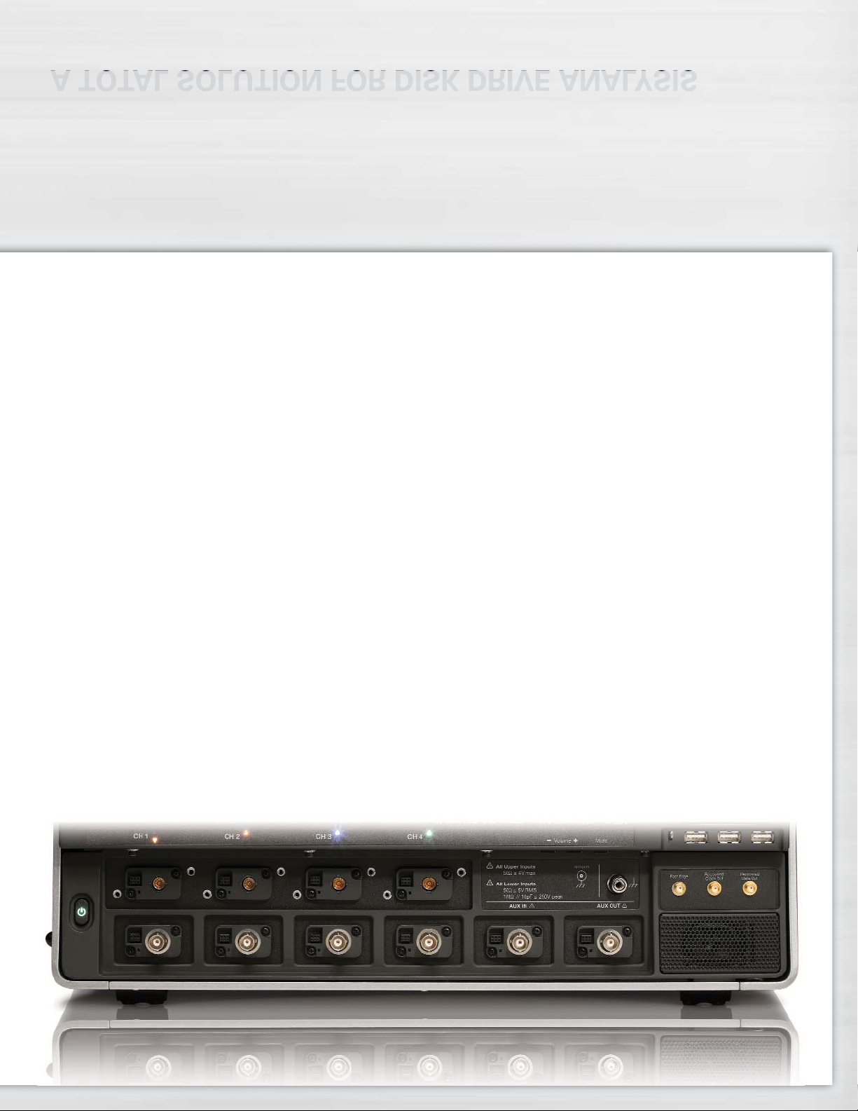
Simultaneously connecting low-speed signals, like index and servo gate, and high-speed signals, like read channels has never
been easier. With integrated 50
Ω
and 1 MΩ inputs on all models, there is no longer a need for expensive adapters.
Page 28

HIGH BANDWIDTH PROBING SOLUTIONS
28
The DA18000 Differential
Amplifier
The DA18000 Differential Amplifier
is a very high bandwidth DC coupled
differential amplifier with a true
100 Ω balanced input. It features
high common mode rejection and
low noise. The amplifier has unity
gain, to maximize the signal to noise
performance when used with the
lower amplitude signal voltages
common in higher data rate systems.
The DA18000 is supplied with a
short pair of input cables which are
matched to an electrical propagation
length of 2.5 ps. Use of the DA18000
with these cables eliminates the
need to deskew and calibrate input
channels for differential match, a
problem encountered when acquiring
differential signals with two oscillo-
scope channels connected with
long cables.
The DA18000 differential amplifier
utilizes third generation digital re-
sponse equalization, the same calibra-
tion method used in LeCroy’s award
winning high bandwidth probes. This
provides the most accurate magnitude
and phase response, assuring the high
fidelity eye pattern measurements.
Specification Value
Input Configuration
True Differential, 100 Ω Balanced
Input Connector
2.92 mm
Frequency Response, System
DC–18 GHz, Typical
Rise time, 20%–80%, System
< 24 ps, Typical
Rise time, 20%-80%, Probe Only
< 19 ps
Voltage Gain
X 1
Voltage Gain Accuracy
2%, (20–30 ºC)
Max. Offset Voltage, RTI
< 5 mV
Noise, System
1 mV
rms,
Typical
Maximum Input – Differential
±400 mV (800 mV
p-p
)
with ÷2 Attenuators
±800 mV (1.6 V
p-p
)
Maximum Input – Common Mode
±10 V
with ÷2 Attenuators
7 V
rms
Common Mode Resistance, DC
25 kΩ
Included with the DA18000:
Electrically matched input cables (2), ÷2 precision attenuators (2),
ESD dissipating wrist strap, Instruction Manual, certificate of traceable
calibration, soft accessory case.
D13000PS/D11000PS
Differential Probe System
The D13000PS/D11000PS extends
the full signal acquisition performance
of WaveMaster 8 Zi to the probe tips.
With 13/11 GHz system bandwidth,
the probe enables direct measure-
ment of high-speed serial data
streams up to 6.25 Gb/s.
The D13000PS/D11000PS provides
unprecedented waveform fidelity,
even with signals at higher serial
data rates. Each probe utilizes third
generation response compensation
calibration, the most advanced in
use today, to provide optimal
system response.
The D13000PS/D11000PS provides
both direct Solder-In and cabled
SMA-connector interconnect lead
assemblies. The D13000PS also
provides SMP cables for additional
cabling options. Each interconnect
lead comes with a dedicated probe
amplifier module that has calibration
data optimized for the respective
lead. This eliminates the performance
compromise of using a single
calibration for multiple lead types.
Page 29

OTHER PROBING SOLUTIONS
All probes described below may be used with any
WaveMaster 8 Zi oscilloscope. In addition, passive
probes (not shown here) may also be used.
29
ADP305, ADP300
• 20 MHz and 100 MHz bandwidth
• 1,000 V
rms
common mode voltage
• 1,400 V
peak
differential voltage
• EN 61010 CAT III
• 80 dB CMRR at 50/60 Hz
• LeCroy ProBus
system
ZS Series High Impedance
Active Probes
• 1 GHz (ZS1000) and 1.5 GHz
(ZS1500) bandwidths
• High Impedance (0.9 pF, 1 MΩ)
• Extensive standard and available
probe tip and ground connection
accessories
• ±12 Vdc offset
(ZS1500)
• LeCroy
ProBus
system
PPE1.2KV, PPE2KV, PPE4KV,
PPE5KV, PPE6KV, PPE20KV
• Suitable for safe, accurate
high-voltage measurements
• 1.2 kV to 20 kV
• Works with any 1 MΩ input
oscilloscope
AP033 and AP034
• 500 MHz and 1 GHz bandwidth
• 10,000:1 CMRR
• Wide dynamic range, low noise
• LeCroy ProBus System
WaveLink Differential Probes
• 3 and 6 GHz models
• Excellent noise performance
• ±4 V offset
• ±3 V common mode control
• Solder-In, Browser, Quick-Connect,
and Square Pin tip
CP030 and CP031
• 30 A
rms
continuous current
• 50 or 100 MHz bandwidth
• Measure pulses up to 50 A
peak
• Small form factor accommodates
large conductors with small
jaw size
• LeCroy ProBus
system
AP031
• Lowest priced
differential probe
• 15 MHz
bandwidth
• 700 V maximum
input voltage
• Works with any
1 MΩ input oscilloscope
Page 30

30
SPECIFICATIONS
WaveMaster WaveMaster WaveMaster WaveMaster WaveMaster
Vertical System 804Zi (SDA) 806Zi (SDA) 808Zi (SDA) 813Zi (SDA) 816Zi (SDA,DDA)
Analog (2.92 mm Input) – – – – –
Bandwidth @ 50 Ω (-3 dB)
Analog (ProLink Input) 4 GHz 6 GHz 8 GHz 13 GHz 16 GHz
Bandwidth @ 50 Ω (-3 dB) (≥ 10 mV/div) (≥ 10 mV/div) (≥ 10 mV/div) (≥ 10 mV/div) (≥ 10 mV/div)
Analog (ProBus Input) 3.5 GHz 3.5 GHz 3.5 GHz 3.5 GHz 3.5 GHz
Bandwidth @ 50 Ω (-3 dB) (≥ 10 mV/div) (≥ 10 mV/div) (≥ 10 mV/div) (≥ 10 mV/div) (≥ 10 mV/div)
Analog (ProBus Input) 500 MHz (typical, ≥ 2 mV/div)
Bandwidth @ 1 MΩ (-3 dB)
Rise Time (test limit, flatness mode 95 ps 63 ps 49 ps 32.5 ps 28.5 ps
10–90%, 50 Ω)
Rise Time (flatness mode, 71 ps 47 ps 37 ps 24.5 ps 21.5 ps
20-80%, 50 Ω)
Input Channels 4 (Any combination of ProLink and ProBus inputs)
Bandwidth Limiters 20 MHz, 200 MHz, 20 MHz, 200 MHz, 20 MHz, 200 MHz, 20 MHz, 200 MHz, 20 MHz, 200 MHz,
1 GHz 1 GHz, 4 GHz 1 GHz, 1 GHz, 4 GHz, 1 GHz, 4 GHz, 6 GHz,
4 GHz, 6 GHz 6 GHz, 8 GHz 8 GHz, 13 GHz
Input Impedance ProLink Inputs: 50 Ω ±2% for ≤ 100 mV/div, 50 Ω ±3% for > 100 mV/div
ProBus Inputs: 50 Ω ±2% or 1 MΩ || 16 pF, 10 MΩ || 11 pF with supplied Probe
Input Coupling ProLink Inputs: 50 Ω: DC, GND
ProBus Inputs: 1 MΩ: AC, DC, GND; 50 Ω: DC, GND
Maximum Input Voltage 50 Ω (ProLink): ±2 V max. @ ≤ 100 mV/div, 5.5 Vrms @ > 100 mV/div
50 Ω (ProBus): ±5 V max., 3.5 V
rms
1 MΩ (ProBus): 250 V max. (peak AC: < 10 kHz + DC)
Channel-Channel Isolation DC to 10 GHz: 50 dB (> 315:1)
10 to 15 GHz: 46 dB (> 200:1)
15 to 16 GHz: 40 dB (> 100:1)
(For any two ProLink input channels, same or different v/div settings, typical)
Vertical Resolution 8 bits up to 11 bits with enhanced resolution (ERES)
Sensitivity 50 Ω (ProLink): 2 mV–1 V/div, fully variable (2–9.9 mV/div via zoom)
50 Ω (ProBus): 2 mV–1 V/div, fully variable
1 MΩ (ProBus): 2 mV–10 V/div, fully variable
DC Gain Accuracy ±1.5% of full scale
Offset Range 50 Ω (ProLink):
±500 mV @ 2–100 mV/div
±4 V @ > 100 mV/div–1 V/div
50 Ω (ProBus):
±750 mV @ 2–100 mV/div
±4 V @ > 100 mV/div–1 V/div
1 MΩ:
±1 V @ 2–140 mV/div
±10 V @ 142 mV–1.40 V/div
±100 V @ 1.42 V–10 V/div
Offset Accuracy ±(1.5% of full scale + 1.5% of offset value + 2 mV)
Horizontal System
Timebases Internal timebase common to 4 input channels; an external clock may be applied at the auxiliary input
Time/Division Range 20 ps/div–128 s/div (Real-time Mode: 20 ps/div–64 s/div; RIS mode: 20 ps/div–10 ns/div; Roll mode: 100 ms/div
up to 128 s/div), depending on memory length
Clock Accuracy < 1 ppm + (aging of 0.5 ppm/yr from last calibration)
Time Interval Accuracy < 0.06 / SR + (clock accuracy* Reading) (rms)
Page 31

SPECIFICATIONS
31
WaveMaster WaveMaster WaveMaster
Vertical System 820Zi (SDA) 825Zi (SDA, DDA) 830Zi (SDA)
Analog (2.92 mm Input) 20 GHz 25 GHz 30 GHz
Bandwidth @ 50 Ω (-3 dB)
Analog (ProLink Input) 16 GHz 16 GHz 16 GHz
Bandwidth @ 50 Ω (-3 dB) (≥ 10 mV/div) (≥ 10 mV/div) (≥ 10 mV/div)
Analog (ProBus Input) 3.5 GHz 3.5 GHz 3.5 GHz
Bandwidth @ 50 Ω (-3 dB) (≥ 10 mV/div) (≥ 10 mV/div) (≥ 10 mV/div)
Analog (ProBus Input) 500 MHz (typical, ≥ 2 mV/div)
Bandwidth @ 1 MΩ (-3 dB)
Rise Time (test limit, flatness mode 20 ps (@ full BW) 17.5 ps (@ full BW) 15.5 ps (@ full BW)
10–90%, 50 Ω)
Rise Time (flatness mode, 15 ps 13 ps 11.5 ps
20-80%, 50 Ω)
Input Channels 4 (Any combination of 16 GHz ProLink inputs or 3.5 GHz ProBus inputs),
3 (1 @ full BW, 2 with ProLink or ProBus inputs), or 2 (@ full BW)
Bandwidth Limiters For < 20 GHz Mode: 20 MHz, For < 20 GHz Mode: 20 MHz, For < 20 GHz Mode: 20 MHz,
200 MHz, 1 GHz, 4 GHz, 200 MHz, 1 GHz, 4 GHz, 200 MHz, 1 GHz, 4 GHz,
6 GHz, 8 GHz, 13 GHz 6 GHz, 8 GHz, 13 GHz 6 GHz, 8 GHz, 13 GHz
For ≥ 20 GHz Mode: For ≥ 20 GHz Mode: For ≥ 20 GHz Mode:
None 20 GHz 20 GHz, 25 GHz
Input Impedance 2.92 mm Inputs: 50 Ω ±2% for ≤ 79 mV/div, 50 Ω ±3% for > 79 mV/div
ProLink Inputs: 50 Ω ±2% for ≤ 100 mV/div, 50 Ω ±3% for > 100 mV/div
ProBus Inputs: 50 Ω ±2% or 1 MΩ || 16 pF, 10 MΩ || 11 pF with supplied Probe
Input Coupling 2.92 mm Inputs: 50 Ω: DC, GND
ProLink Inputs: 50 Ω: DC, GND
ProBus Inputs: 1 MΩ: AC, DC, GND; 50 Ω: DC, GND
Maximum Input Voltage 2.92 mm Inputs: ±2 V max. @ ≤ 100 mV/div, 5.5 V
rms
@ > 100 mV/div
50 Ω (ProLink): ±2 V max. @ ≤ 100 mV/div, 5.5 V
rms
@ > 100 mV/div
50 Ω (ProBus): ±5 V max., 3.5 V
rms
1 MΩ (ProBus): 250 V max. (peak AC: < 10 kHz + DC)
Channel-Channel Isolation DC to 10 GHz: 50 dB (> 315:1)
10 to 15 GHz: 46 dB (> 200:1)
15 to 16 GHz: 40 dB (> 100:1)
16 GHz to Max BW: 30 dB (> 32:1)
(For any two ProLink or 2.92 mm input channels, same or different v/div settings, typical)
Vertical Resolution 8 bits up to 11 bits with enhanced resolution (ERES)
Sensitivity 50 Ω (2.92 mm): 10 mV–500 mV/div
50 Ω (ProLink): 2 mV–1 V/div, fully variable (2–9.9 mV/div via zoom)
50 Ω (ProBus): 2 mV–1 V/div, fully variable
1 MΩ (ProBus): 2 mV–10 V/div, fully variable
DC Gain Accuracy ±1.5% of full scale
Offset Range 50 Ω (2.92 mm):
±500 mV @ 2–79 mV/div
±4 V @ 80 mV/div–500 mV/div
50 Ω (ProLink):
±500 mV @ 2–100 mV/div
±4 V @ > 100 mV/div–1 V/div
50 Ω (ProBus):
±750 mV @ 2–100 mV/div
±4 V @ > 100 mV/div–1 V/div
1 MΩ:
±1 V @ 2–140 mV/div
±10 V @ 142 mV–1.40 V/div
±100 V @ 1.42 V–10 V/div
Offset Accuracy ±(1.5% of full scale + 1.5% of offset value + 2 mV)
Horizontal System
Timebases Internal timebase common to 4 input channels; an external clock may be applied at the auxiliary input
Time/Division Range For ≥ 20 GHz Mode: Real-time Mode, 20 ps/div–12.5 s/div, depending on memory length
For < 20 GHz Mode: 20 ps/div–128 s/div (Real-time Mode: 20 ps/div–64 s/div; RIS mode: 20 ps/div–10 ns/div;
Roll mode: 100 ms/div up to 128 s/div), depending on memory length
Clock Accuracy < 1 ppm + (aging of 0.5 ppm/yr from last calibration)
Time Interval Accuracy < 0.06 / SR + (clock accuracy* Reading) (rms)
Page 32

32
SPECIFICATIONS
WaveMaster WaveMaster WaveMaster WaveMaster WaveMaster
Horizontal System (cont’d) 804Zi (SDA) 806Zi (SDA) 808Zi (SDA) 813Zi (SDA) 816Zi (SDA, DDA)
Jitter Noise Floor For Acq. Length For Acq. Length For Acq. Length For Acq. Length For Acq. Length
≤ 10 µs: 600 fs
rms
≤ 10 µs: 450 fs
rms
≤ 10 µs: 400 fs
rms
≤ 10 µs: 375 fs
rms
≤ 10 µs: 290 fs
rms
(TIE, typical) (TIE, typical) (TIE, typical) (TIE, typical) (TIE, typical)
For Acq. Length For Acq. Length For Acq. Length For Acq. Length For Acq. Length
> 10 µs: 650 fs
rms
> 10 µs: 500 fs
rms
> 10 µs: 450 fs
rms
> 10 µs: 425 fs
rms
> 10 µs: 340 fs
rms
(TIE, typical) (TIE, typical) (TIE, typical) (TIE, typical) (TIE, typical)
Trigger and Interpolator Jitter 2 ps rms (typical)
< 0.1 ps rms (typical, software assisted)
Channel-Channel Deskew Range ±9 x time/div. setting or 25 ns max. (whichever is larger), each channel
External Timebase Reference (Input) 10 MHz 50 Ω impedance, applied at the rear input
External Timebase Reference 10 MHz 50 Ω impedance, output at the rear
(Output)
Acquisition System
Single-Shot Sample Rate/Ch 40 GS/s on 4 Ch
(80 GS/s on 2 Ch using optional WM8Zi-2X80GS External Interleaving Device)
Random Interleaved Sampling (RIS) 200 GS/s for repetitive signals (20 ps/div to 10 ns/div)
Maximum Trigger Rate 1,000,000 waveforms/second (in Sequence Mode, up to 4 channels)
Intersegment Time 1 µs
Maximum Acquisition and Analysis
Memory Points/Ch 4 Ch Memory Number of Segments
Standard Memory 10 M / 10 M (optional WM8Zi-2X80GS External Interleaving Device permits 5,000
80 GS/s on 2 Ch with twice the memory)
S – Memory Option 32 M / 32 M (optional WM8Zi-2X80GS External Interleaving Device permits 15,000
80 GS/s on 2 Ch with twice the memory)
M – Memory Option 64 M / 64 M (optional WM8Zi-2X80GS External Interleaving Device permits 15,000
80 GS/s on 2 Ch with twice the memory)
L – Memory Option 128 M / 128 M (optional WM8Zi-2X80GS External Interleaving Device permits 15,000
80 GS/s on 2 Ch with twice the memory)
VL – Memory Option 256 M / 256 M (optional WM8Zi-2X80GS External Interleaving Device permits 15,000
80 GS/s on 2 Ch with twice the memory)
Acquisition Processing
Averaging Summed averaging to 1 million sweeps continuous averaging to 1 million sweeps
Enhanced Resolution (ERES) From 8.5 to 11 bits vertical resolution
Envelope (Extrema) Envelope, floor, or roof for up to 1 million sweeps
Interpolation Linear or Sin x/x
Triggering System
Modes Normal, Auto, Single, and Stop
Sources Any input channel, Aux, Aux/10, Line, or Fast Edge. Slope and level unique to each source (except line trigger)
Coupling Mode DC, AC, HFRej, LFRej
Pre-trigger Delay 0–100% of memory size (adjustable in 1% increments of 100 ns)
Post-trigger Delay 0–10,000 divisions in real time mode, limited at slower time/div settings or in roll mode
Hold-off by Time or Events From 2 ns up to 20 s or from 1 to 99,999,999 events
Internal Trigger Range ±4.1 div from center
Trigger Sensitivity with Edge Trigger 2 div @ < 3.5 GHz
(Ch 1–4) ProBus Inputs 1.5 div @ < 1.75 GHz
1.0 div @ < 200 MHz
(for DC, coupling, ≥ 10 mV/div, 50 Ω)
Trigger Sensitivity with Edge Trigger 2 div @ < 4 GHz 2 div @ < 6 GHz 2 div @ < 8 GHz 3 div @ < 13 GHz 3 div @ < 15 GHz
(Ch 1–4) ProLink Inputs 1.5 div @ < 3 GHz 1.5 div @ < 3 GHz 1.5 div @ < 3 GHz 1.5 div @ < 3 GHz 1.5 div @ < 3 GHz
1.0 div @ < 200 MHz 1.0 div @ < 200 MHz 1.0 div @ < 200 MHz 1.0 div @ < 200 MHz 1.0 div @ < 200 MHz
(for DC, coupling, (for DC, coupling, (for DC, coupling, (for DC, coupling, (for DC, coupling,
≥ 10 mV/div, 50 Ω) ≥ 10 mV/div, 50 Ω) ≥ 10 mV/div, 50 Ω) ≥ 10 mV/div, 50 Ω) ≥ 10 mV/div, 50 Ω)
External Trigger Sensitivity, 2 div @ < 1 GHz
(Edge Trigger) 1.5 div @ < 500 MHz
1.0 div @ < 200 MHz
(for DC, coupling)
Page 33

SPECIFICATIONS
33
WaveMaster WaveMaster WaveMaster
Horizontal System (cont’d) 820Zi (SDA) 825Zi (SDA, DDA) 830Zi (SDA)
Jitter Noise Floor For Acq. Length ≤ 10 µs: For Acq. Length ≤ 10 µs: For Acq. Length ≤ 10 µs:
265 fs
rms
(TIE, typical) 235 fs
rms
(TIE, typical) 200 fs
rms
(TIE, typical)
For Acq. Length > 10 µs: For Acq. Length > 10 µs: For Acq. Length > 10 µs:
300 fs
rms
(TIE, typical) 275 fs
rms
(TIE, typical) 240 fs
rms
(TIE, typical)
Trigger and Interpolator Jitter 2 ps rms (typical)
< 0.1 ps rms (typical, software assisted)
Channel-Channel Deskew Range ±9 x time/div. setting or 25 ns max. (whichever is larger), each channel
External Timebase Reference (Input) 10 MHz 50 Ω impedance, applied at the rear input
External Timebase Reference 10 MHz 50 Ω impedance, output at the rear
(Output)
Acquisition System
Single-Shot Sample Rate/Ch 40 GS/s on 4 Ch
(80 GS/s on 2 Ch when operated in ≥ 20 GHz Mode)
Random Interleaved Sampling (RIS) For ≥ 20 GHz Mode: Not Applicable
For < 20 GHz Mode: 200 GS/s for repetitive signals (20 ps/div to 10 ns/div)
Maximum Trigger Rate 1,000,000 waveforms/second (in Sequence Mode, up to 4 channels)
Intersegment Time 1 µs
Maximum Acquisition and Analysis
Memory Points/Ch 4 Ch Memory Number of Segments
Standard Memory 10 M / 10 M (20 Mpts in 2 Ch mode when operated in ≥ 20 GHz Mode) 5,000
S – Memory Option 32 M / 32 M (64 Mpts in 2 Ch mode when operated in ≥ 20 GHz Mode) 15,000
M – Memory Option 64 M / 64 M (128 Mpts in 2 Ch mode when operated in ≥ 20 GHz Mode) 15,000
L – Memory Option 128 M / 128 M (256 Mpts in 2 Ch mode when operated in ≥ 20 GHz Mode) 15,000
VL – Memory Option 256 M / 256 M (512 Mpts in 2 Ch mode when operated in ≥ 20 GHz Mode) 15,000
Acquisition Processing
Averaging Summed averaging to 1 million sweeps continuous averaging to 1 million sweeps
Enhanced Resolution (ERES) From 8.5 to 11 bits vertical resolution
Envelope (Extrema) Envelope, floor, or roof for up to 1 million sweeps
Interpolation Linear or Sin x/x
Triggering System
Modes Normal, Auto, Single, and Stop
Sources Any input channel, Aux, Aux/10, Line, or Fast Edge. Slope and level unique to each source (except line trigger)
Coupling Mode DC, AC, HFRej, LFRej
Pre-trigger Delay 0–100% of memory size (adjustable in 1% increments of 100 ns)
Post-trigger Delay 0–10,000 divisions in real time mode, limited at slower time/div settings or in roll mode
Hold-off by Time or Events From 2 ns up to 20 s or from 1 to 99,999,999 events
Internal Trigger Range ±4.1 div from center
Trigger Sensitivity with Edge Trigger 2 div @ < 3.5 GHz
(Ch 1–4) ProBus Inputs 1.5 div @ < 1.75 GHz
1.0 div @ < 200 MHz
(for DC coupling, ≥ 10 mV/div, 50 Ω)
Trigger Sensitivity with Edge Trigger 3 div @ < 15 GHz
(Ch 1–4) ProLink Link and 1.5 div @ < 3 GHz
2.92 mm Inputs 1.0 div @ < 200 MHz
(for DC coupling, ≥ 10 mV/div, 50 Ω)
External Trigger Sensitivity, 2 div @ < 1 GHz
(Edge Trigger) 1.5 div @ < 500 MHz
1.0 div @ < 200 MHz
(for DC coupling)
Page 34

34
SPECIFICATIONS
WaveMaster WaveMaster WaveMaster WaveMaster WaveMaster
Triggering System (cont’d) 804Zi (SDA) 806Zi (SDA) 808Zi (SDA) 813Zi (SDA) 816Zi (SDA, DDA)
Max. Trigger Frequency, 2.0 GHz @ ≥ 10 mV/div (minimum triggerable width 200 ps)
SMART Trigger
External Trigger Input Range Aux (±0.4 V); Aux/10 (±4 V)
Basic Triggers
Edge Triggers when signal meets slope (positive, negative, or either) and level condition
Window Triggers when signal exits a window defined by adjustable thresholds
TV-Composite Video Triggers NTSC or PAL with selectable line and field HDTV (720p, 1080i, 1080p) with selectable frame rate
(50 or 60 Hz) and Line or CUSTOM with selectable Fields (1–8), Lines (up to 2000), Frame Rates (25, 30, 50, or
60 Hz), Interlacing (1:1, 2:1, 4:1, 8:1), or Synch Pulse Slope (Positive or Negative)
SMART Triggers
™
State or Edge Qualified Triggers on any input source only if a defined state or edge occurred on another input source. Holdoff between
sources is selectable by time or events
Qualified First In Sequence acquisition mode, triggers repeatably on event B only if a defined pattern, state, or edge (event A)
is satisfied in the first segment of the acquisition. Holdoff between sources is selectable by time or events
Dropout Triggers if signal drops out for longer than selected time between 1 ns and 20 s
Pattern Logic combination (AND, NAND, OR, NOR) of 5 inputs (4 channels and external trigger input).
Each source can be high, low, or don’t care. The High and Low level can be selected independently.
Triggers at start or end of the pattern
SMART Triggers with
Exclusion Technology
Glitch Triggers on positive or negative glitches with widths selectable as low as 200 ps to 20 s, or on intermittent faults
Width (Signal or Pattern) Triggers on positive, negative, or both widths with widths selectable as low as 200 ps to 20 s, or
on intermittent faults
Interval (Signal or Pattern) Triggers on intervals selectable between 1 ns and 20 s
Timeout (State/Edge Qualified) Triggers on any source if a given state (or transition edge) has occurred on another source.
Holdoff between sources is 1 ns to 20 s, or 1 to 99,999,999 events
Runt Trigger on positive or negative runts defined by two voltage limits and two time limits.
Select between 1 ns and 20 ns
Slew Rate Trigger on edge rates. Select limits for dV, dt, and slope. Select edge limits between 1 ns and 20 ns
Exclusion Triggering Trigger on intermittent faults by specifying the expected behavior and triggering when that condition is not met
Cascade (Sequence) Triggering
Capability Arm on “A” event, then Trigger on “B” event. Or Arm on “A” event, then Qualify on “B” event, and Trigger on
“C” event. Or Arm on “A” event, then Qualify on “B” then “C” event, and Trigger on “D” event
Types A, B, C, or D event: Edge, Glitch, Width, Window, Dropout, Interval, Runt, Slew Rate, or Pattern (analog)
Holdoff Holdoff between A and B, B and C, C and D, are all selectable by time or number of events
Reset Reset between A and B, B and C, C and D, are all selectable in time or number of events
High-speed Serial Protocol
Triggering
(Option WM8Zi-HSPT,
Standard on SDA Models)
Data Rates 100 Mb/s–2.7 Gb/s, 3.0, 3.125 Gb/s
Pattern Length 80-bits, NRZ or 8b/10b
Clock and Data Outputs 400 mV
p-p
(typical) AC coupled
Clock Recovery Jitter 2 ps rms + 0.3% Unit Interval rms for PRBS data patterns with 50% transition density (typical)
Hardware Clock Recovery Loop BW PLL Loop BW = Fbaud/5500, 100 Mb/s to 2.488 Gb/s (typical)
Low-speed Serial Protocol
Triggering (Optional)
Optionally Available I2C, SPI (SPI, SSPI, SIOP), UART-RS232, CAN, LIN, FlexRay
Color Waveform Display
Type Color 15.3" flat panel TFT-Active Matrix LCD with high resolution touch screen
Resolution WXGA; 1280 x 768 pixels.
Number of Traces Display a maximum of 8 traces. Simultaneously display channel, zoom, memory and math traces
Grid Styles Auto, Single, Dual, Quad, Octal, X-Y, Single+X-Y, Dual+X-Y
Waveform Representation Sample dots joined, or sample dots only
Page 35

SPECIFICATIONS
WaveMaster WaveMaster WaveMaster
Triggering System (cont’d) 820Zi (SDA) 825Zi (SDA, DDA) 830Zi (SDA)
Max. Trigger Frequency, 2.0 GHz @ ≥ 10 mV/div (minimum triggerable width 200 ps)
SMART Trigger
External Trigger Input Range Aux (±0.4 V); Aux/10 (±4 V)
Basic Triggers
Edge Triggers when signal meets slope (positive, negative, or either) and level condition
Window Triggers when signal exits a window defined by adjustable thresholds
TV-Composite Video Triggers NTSC or PAL with selectable line and field HDTV (720p, 1080i, 1080p) with selectable frame rate
(50 or 60 Hz) and Line or CUSTOM with selectable Fields (1–8), Lines (up to 2000), Frame Rates (25, 30, 50, or
60 Hz), Interlacing (1:1, 2:1, 4:1, 8:1), or Synch Pulse Slope (Positive or Negative)
SMART Triggers
™
State or Edge Qualified Triggers on any input source only if a defined state or edge occurred on another input source. Holdoff between
sources is selectable by time or events
Qualified First In Sequence acquisition mode, triggers repeatably on event B only if a defined pattern, state, or edge (event A)
is satisfied in the first segment of the acquisition. Holdoff between sources is selectable by time or events
Dropout Triggers if signal drops out for longer than selected time between 1 ns and 20 s.
Pattern Logic combination (AND, NAND, OR, NOR) of 5 inputs (4 channels and external trigger input).
Each source can be high, low, or don’t care. The High and Low level can be selected independently.
Triggers at start or end of the pattern
SMART Triggers with
Exclusion Technology
Glitch Triggers on positive or negative glitches with widths selectable as low as 200 ps to 20 s, or
on intermittent faults
Width (Signal or Pattern) Triggers on positive, negative, or both widths with widths selectable as low as 200 ps to 20 s, or
on intermittent faults
Interval (Signal or Pattern) Triggers on intervals selectable between 1 ns and 20 s
Timeout (State/Edge Qualified) Triggers on any source if a given state (or transition edge) has occurred on another source.
Holdoff between sources is 1 ns to 20 s, or 1 to 99,999,999 events
Runt Trigger on positive or negative runts defined by two voltage limits and two time limits.
Select between 1 ns and 20 ns
Slew Rate Trigger on edge rates. Select limits for dV, dt, and slope. Select edge limits between 1 ns and 20 ns
Exclusion Triggering Trigger on intermittent faults by specifying the expected behavior and triggering when that condition is not met
Cascade (Sequence) Triggering
Capability Arm on “A” event, then Trigger on “B” event. Or Arm on “A” event, then Qualify on “B” event, and Trigger on
“C” event. Or Arm on “A” event, then Qualify on “B” then “C” event, and Trigger on “D” event
Types A, B, C, or D event: Edge, Glitch, Width, Window, Dropout, Interval, Runt, Slew Rate, or Pattern (analog)
Holdoff Holdoff between A and B, B and C, C and D, are all selectable by time or number of events
Reset Reset between A and B, B and C, C and D, are all selectable in time or number of events
High-speed Serial Protocol
Triggering
(Option WM8Zi-HSPT,
Standard on SDA Models)
Data Rates 100 Mb/s–2.7 Gb/s, 3.0, 3.125 Gb/s (standard with SDA 8 Zi models)
Pattern Length 80-bits, NRZ or 8b/10b
Clock and Data Outputs 400 mV
p-p
(typical) AC coupled
Clock Recovery Jitter 2 ps rms + 0.3% Unit Interval rms for PRBS data patterns with 50% transition density (typical)
Hardware Clock Recovery Loop BW PLL Loop BW = Fbaud/5500, 100 Mb/s to 2.488 Gb/s (typical)
Low-speed Serial Protocol
Triggering (Optional)
Optionally available I2C, SPI (SPI, SSPI, SIOP), UART-RS232, CAN, LIN, FlexRay
Color Waveform Display
Type Color 15.3" flat panel TFT-Active Matrix LCD with high resolution touch screen
Resolution WXGA; 1280 x 768 pixels.
Number of Traces Display a maximum of 8 traces. Simultaneously display channel, zoom, memory and math traces
Grid Styles Auto, Single, Dual, Quad, Octal, X-Y, Single+X-Y, Dual+X-Y
Waveform Representation Sample dots joined, or sample dots only
35
Page 36

36
SPECIFICATIONS
WaveMaster WaveMaster WaveMaster WaveMaster WaveMaster
Integrated Second Display 804Zi (SDA) 806Zi (SDA) 808Zi (SDA) 813Zi (SDA) 816Zi (SDA, DDA)
Type Color 15.3" flat panel TFT-Active Matrix LCD with high resolution touch screen
Resolution WXGA 1280 x 768 pixels
LeCroy WaveStream
Fast Viewing Mode
Intensity 256 Intensity Levels, 1–100% adjustable via front panel control
Types Select analog or color-graded
Number of Channels Up to 4 simultaneously
Max. Sampling Rate 40 GS/s (80 GS/s with optional WM8Zi-2X80GS external interleaving device)
Persistence Aging Select from 500 ms to Infinity
Waveforms/Second (Continuous) Up to 2500 waveforms/second
Operation Front panel toggle between WaveStream ON (Analog), ON (Color) and OFF
Analog Persistence Display
Analog and Color-Graded Persistence Variable saturation levels stores each trace’s persistence data in memory
Persistence Types Select analog, color, or three-dimensional
Trace Selection Activate persistence on all or any combination of traces
Persistence Aging Select from 500 ms to infinity
Sweep Display Modes All accumulated, or all accumulated with last trace highlighted
High-speed Digitizer
Output (Option)
Type LeCroy LSIB
Transfer Rate Up to 325 MB/s (Typical)
Output Protocol PCI Express®, Gen1 (4 lanes utilized for data transfer)
Control Protocol TCP/IP
Command Set Via Windows Automation, or via LeCroy Remote Command Set
Zoom Expansion Traces
Display up to 4 Zoom and 8 Math/Zoom traces
Processor/CPU
Type Intel®Core™ 2 Quad, 2.5 GHz (or better)
Processor Memory 4 GB standard, up to 8 GB optional
(8 GB standard with “M-64”, “L-128”, or “VL-256” memory)
Operating System Microsoft Windows®Vista®Business Edition (64-bit) with SP1
Real Time Clock Date and time displayed with waveform an in hardcopy files.
SNTP support to synchronize to precision internal clocks
Internal Waveform Memory
4 active waveform memory traces (M1-M4) store 16-bit/point full length waveforms.
Waveforms can be stored to any number of files limited only by the data storage media capacity
Setup Storage
Front Panel and Instrument Status Store to the internal hard drive, over a network, or to a USB-connected peripheral device
Interface
Remote Control Via Windows Automation, or via LeCroy Remote Command Set
Network Communication Standard VXI-11 or VICP, LXI Class C (v1.2) Compliant
GPIB Port (Optional) Supports IEEE – 488.2
LSIB Port (Optional) Supports PCIe Gen1 x4 protocol with LeCroy supplied API
Ethernet Port Supports 10/100/1000BaseT Ethernet interface (RJ45 port)
USB Ports Minimum 6 total (incl. 3 front panel) USB 2.0 ports support Windows compatible devices
External Monitor Port 15-pin D-Type WXGA compatible to support customer-supplied external monitor.
DVI connector to support LeCroy Zi-EXTDISP-15 additional touch screen display accessory.
Includes support for extended desktop operation with optional LeCroy or other second monitor
Peripheral Bus LeCroy LBUS standard
Page 37

SPECIFICATIONS
WaveMaster WaveMaster WaveMaster
Integrated Second Display 820Zi (SDA) 825Zi (SDA, DDA) 830Zi (SDA)
Type Color 15.3" flat panel TFT-Active Matrix LCD with high resolution touch screen
Resolution WXGA 1280 x 768 pixels
LeCroy WaveStream
Fast Viewing Mode
Intensity 256 Intensity Levels, 1–100% adjustable via front panel control
Types Select analog or color-graded
Number of Channels Up to 4 simultaneously
Max. Sampling Rate 40 GS/s (80 GS/s when operated in ≥ 20 GHz Mode)
Persistence Aging Select from 500 ms to Infinity
Waveforms/Second (Continuous) Up to 2500 waveforms/second
Operation Front panel toggle between WaveStream ON (Analog), ON (Color) and OFF
Analog Persistence Display
Analog and Color-Graded Persistence Variable saturation levels stores each trace’s persistence data in memory
Persistence Types Select analog, color, or three-dimensional
Trace Selection Activate persistence on all or any combination of traces
Persistence Aging Select from 500 ms to infinity
Sweep Display Modes All accumulated, or all accumulated with last trace highlighted
High-speed Digitizer
Output (Option)
Type LeCroy LSIB
Transfer Rate Up to 325 MB/s (Typical)
Output Protocol PCI Express®, Gen1 (4 lanes utilized for data transfer)
Control Protocol TCP/IP
Command Set Via Windows Automation, or via LeCroy Remote Command Set
Zoom Expansion Traces
Display up to 4 Zoom and 8 Math/Zoom traces
Processor/CPU
Type Intel®Core™ 2 Quad, 2.5 GHz (or better)
Processor Memory 4 GB standard, up to 8 GB optional
(8 GB standard with “M-64”, “L-128”, or “VL-256” memory)
Operating System Microsoft Windows®Vista®Business Edition (64-bit) with SP1
Real Time Clock Date and time displayed with waveform an in hardcopy files.
SNTP support to synchronize to precision internal clocks
Internal Waveform Memory
4 active waveform memory traces (M1-M4) store 16 bit/point full length waveforms.
Waveforms can be stored to any number of files limited only by the data storage media capacity
Setup Storage
Front Panel and Instrument Status Store to the internal hard drive, over a network, or to a USB-connected peripheral device
Interface
Remote Control Via Windows Automation, or via LeCroy Remote Command Set
Network Communication Standard VXI-11 or VICP, LXI Class C (v1.2) Compliant
GPIB Port (Optional) Supports IEEE – 488.2
LSIB Port (Optional) Supports PCIe Gen1 x4 protocol with LeCroy supplied API
Ethernet Port Supports 10/100/1000BaseT Ethernet interface (RJ45 port)
USB Ports Minimum 6 total (incl. 3 front panel) USB 2.0 ports support Windows compatible devices
External Monitor Port 15-pin D-Type WXGA compatible to support customer-supplied external monitor.
DVI connector to support LeCroy Zi-EXTDISP-15 additional touch screen display accessory.
Includes support for extended desktop operation with optional LeCroy or other second monitor
Peripheral Bus LeCroy LBUS standard
37
Page 38

38
SPECIFICATIONS
WaveMaster WaveMaster WaveMaster WaveMaster WaveMaster
Auxiliary Input 804Zi (SDA) 806Zi (SDA) 808Zi (SDA) 813Zi (SDA) 816Zi (SDA, DDA)
Signal Types Select External Trigger or External Clock Input on the front panel
Coupling 50 Ω: DC 1 MΩ: AC, DC, GND
Max. Input Voltage 50 Ω: 5 V
rms
1 MΩ: 250 V (Peak AC < 10 kHz + DC)
Auxiliary Output
Signal Types Select from calibrator, control signals or Off
Calibrator Signal 500 Hz–5 MHz square wave or DC level 0.0 to 500 mV into 50 Ω (0–1 V into 1 MΩ)
Control Signals Trigger enabled, trigger out, pass/fail status, Off.
Connector Type BNC, located on front
Automatic Setup
Auto Setup Automatically sets timebase, trigger, and sensitivity to display a wide range of repetitive signals
Find Vertical Scale Automatically sets the vertical sensitivity and offset for the selected channel to display a waveform
with the maximum dynamic range
General
Auto Calibration Ensures specified DC and timing accuracy is maintained for 1 year minimum
Probes
Probes Qty. (4) ÷10 Passive Probes
Probe System ProBus and ProLink. Automatically detects and supports a variety of compatible probes
Scale Factors Automatically or manually selected depending on probe used
Calibration Output 1 kHz square wave, 1 V
p-p
(typical), output to probe hook
Power Requirements
Voltage 100–240 VAC ±10% at 45–66 Hz 100–120 VAC ±10% at 380–420 Hz Automatic AC Voltage Selection
Max. Power Consumption 975 W / 975 VA
Environmental
Temperature (Operating) +5 °C to +40 °C including CD-RW/DVD-ROM drive
Temperature (Non-Operating) –20 °C to +60 °C
Humidity (Operating) 5% to 80% relative humidity (non-condensing) up to +31 °C.
Upper limit derates to 50% relative humidity (non-condensing) at +40 °C
Humidity (Non-Operating) 5% to 95% relative humidity (non-condensing) as tested per MIL-PRF-28800F
Altitude (Operating) Up to 10,000 ft. (3048 m) at or below +25 °C
Altitude (Non-Operating) Up to 40,000 ft. (12,192 m)
Random Vibration (Operating) 0.5 g
rms
overall level, 5 Hz to 500 Hz, 10 minutes in each of three orthogonal axes, 30 minutes total
Random Vibration (Non-Operating) 2.0 g
rms
overall level, 5 Hz to 500 Hz, 10 minutes in each of three orthogonal axes, 30 minutes total
Functional Shock 20 g
peak
, half sine, 11 ms pulse, 3 shocks (positive and negative) in each of three orthogonal axes, 18 shocks total
Physical Dimensions
Dimensions (HWD) 14" H x 18.4" W x 15.3" D (355 x 467 x 390 mm) height excludes feet
Weight 51.5 lbs. (23.4 kg)
Shipping Weight 70 lbs. (31.8 kg)
Certifications
CE Compliant, UL and cUL listed conforms to EN 61326-1, EN 61010-1, UL 61010-1 2nd edition,
and CSA C22.2 No. 61010-1-04
Warranty and Service
3-year warranty calibration recommended annually.
Optional service programs include extended warranty, upgrades, and calibration services.
Page 39

WaveMaster WaveMaster WaveMaster
Auxiliary Input 820Zi (SDA) 825Zi (SDA, DDA) 830Zi (SDA)
Signal Types Select External Trigger or External Clock Input on the front panel
Coupling 50 Ω: DC 1 MΩ: AC, DC, GND
Max. Input Voltage 50 Ω: 5 V
rms
1 MΩ: 250 V (Peak AC < 10 kHz + DC)
Auxiliary Output
Signal Types Select from calibrator, control signals or OFF
Calibrator Signal 500 Hz–5 MHz square wave or DC level 0.0 to 500 mV into 50 Ω (0–1 V into 1 MΩ)
Control Signals Trigger enabled, trigger out, pass/fail status, OFF.
Connector Type BNC, located on front
Automatic Setup
Auto Setup Automatically sets timebase, trigger, and sensitivity to display a wide range of repetitive signals
Find Vertical Scale Automatically sets the vertical sensitivity and offset for the selected channel to display a waveform with the
maximum dynamic range
General
Auto Calibration Ensures specified DC and timing accuracy is maintained for 1 year minimum
Probes
Probes Qty. (4) ÷10 Passive Probes
Probe System ProBus and ProLink. Automatically detects and supports a variety of compatible probes
Scale Factors Automatically or manually selected depending on probe used
Calibration Output 1 kHz square wave, 1 V
p-p
(typical), output to probe hook
Power Requirements
Voltage 100–240 VAC ±10% at 45–66 Hz 100–120 VAC ±10% at 380–420 Hz Automatic AC Voltage Selection
Max. Power Consumption 1025 W / 1025 VA
Environmental
Temperature (Operating) +5 °C to +40 °C including CD-RW/DVD-ROM drive
Temperature (Non-Operating) –20 °C to +60 °C
Humidity (Operating) 5% to 80% relative humidity (non-condensing) up to +31 °C.
Upper limit derates to 50% relative humidity (non-condensing) at +40 °C
Humidity (Non-Operating) 5% to 95% relative humidity (non-condensing) as tested per MIL-PRF-28800F
Altitude (Operating) Up to 10,000 ft. (3048 m) at or below +25 °C
Altitude (Non-Operating) Up to 40,000 ft. (12,192 m)
Random Vibration (Operating) 0.5 g
rms
overall level, 5 Hz to 500 Hz, 10 minutes in each of three orthogonal axes, 30 minutes total
Random Vibration (Non-Operating) 2.0 g
rms
overall level, 5 Hz to 500 Hz, 10 minutes in each of three orthogonal axes, 30 minutes total
Functional Shock 20 g
peak
, half sine, 11 ms pulse, 3 shocks (positive and negative) in each of three orthogonal axes, 18 shocks total
Physical Dimensions
Dimensions (HWD) 14" H x 18.4" W x 15.3" D (355 x 467 x 390 mm) height excludes feet
Weight 58 lbs. (26.4 kg)
Shipping Weight 76 lbs. (34.5 kg)
Certifications
CE Compliant, UL and cUL listed conforms to EN 61326-1, EN 61010-1, UL 61010-1 2nd edition,
and CSA C22.2 No. 61010-1-04
Warranty and Service
3-year warranty calibration recommended annually.
Optional service programs include extended warranty, upgrades, and calibration services.
SPECIFICATIONS
39
Page 40

Standard
Math Tools
Display up to 8 math function traces (F1–F8). The easy-to-use graphical
interface simplifies setup of up to two operations on each function trace,
and function traces can be chained together to perform math-on-math.
Software Options
SDA II Serial Data Analysis Software (WM8Zi-SDAII)
(Standard on SDA 8 Zi and DDA 8 Zi)
Total Jitter
A complete toolset is provided to measure total jitter. Eye Diagrams with
millions of UI are quickly calculated from up to 512 Mpts records, and
advanced tools may be used on the Eye Diagram to aid analysis. Complete
TIE and Total Jitter (Tj) parameters and analysis functions are provided.
• Time Interval Error (TIE) Measurement Parameter, Histogram,
Spectrum and Jitter Track
• Total Jitter (Tj) Measurement Parameter, Histogram, Spectrum
• Eye Diagram Display (sliced)
• Eye Diagram IsoBER (lines of constant Bit Error Rate)
• Eye Diagram Mask Violation Locator
• Eye Diagram Measurement Parameters
– Eye Height
– One Level
– Zero Level
– Eye Amplitude
– Eye Width
– Eye Crossing
– Avg. Power
– Extinction Ratio
– Mask hits
– Mask out
– Bit Error Rate
– Slice Width (setting)
• Q-Fit Tail Representation
• Bathtub Curve
• Cumulative Density Function (CDF)
• PLL Track
Jitter Decomposition Models
Two jitter decomposition methods are provided and simultaneously
calculated to provide maximum measurement confidence. Q-Scale,
CDF, Bathtub Curve, and all jitter decomposition measurement parameters
can be displayed using either method.
• Spectral Method
• NQ-Scale Method
Random Jitter (Rj) and Non-Data Dependent Jitter (Rj+BUj)
• Random Jitter (Rj) Measurement Parameter
• Rj+BUj Histogram
• Rj+BUj Spectrum
• Rj+BUj Track
Deterministic Jitter (Dj)
• Deterministic Jitter (Dj) Measurement Parameter
Data Dependent Jitter (DDj)
• Data Dependent Jitter (DDj) Measurement Parameter
• DDj Histogram
• DDj Plot (by Pattern or N-bit Sequence)
absolute value
average (summed)
average (continuous)
correlation (two waveforms)
derivative
deskew (resample)
difference (–)
enhanced resolution
(to 11 bits vertical)
envelope
exp (base e)
exp (base 10)
fft (power spectrum, magnitude,
phase, up to 128 Mpts)
floor
integral
interpolate
(cubic, quadratic, sinx/x)
invert (negate)
log (base e)
log (base 10)
product (x)
ratio (/)
reciprocal
rescale (with units)
roof
(sinx)/x
sparse
square
square root
sum (+)
zoom (identity)
Measure Tools
Display any 12 parameters together with statistics, including their average,
high, low, and standard deviations. Histicons provide a fast, dynamic view
of parameters and wave shape characteristics. Parameter Math allows
addition, subtraction, multiplication, or division of two different parameters.
SPECIFICATIONS
amplitude
area
base
cycles
data
delay
Δ delay
duty cycle
duration
falltime (90–10%,
80–20%, @ level)
frequency
first
last
level @ x
maximum
mean
median
minimum
narrow band phase
narrow band power
number of points
+overshoot
–overshoot
peak-to-peak
period
risetime (10–90%,
20–80%, @ level)
rms
std. deviation
top
width
median
phase
time @ minimum (min.)
time @ maximum (max.)
Δ time @ level
Δ time @ level from
trigger
x@ max.
x@ min.
Pass/Fail Testing
Simultaneously test multiple parameters against selectable parameter
limits or pre-defined masks. Pass or fail conditions can initiate actions
including document to local or networked files, e-mail the image of the
failure, save waveforms, send a pulse out at the front panel auxiliary BNC
output, or (with the GPIB option) send a GPIB SRQ.
Jitter and Timing
Parametric Measurements:
• Period@level • Width@level • Duty@level • Frequency@level
• TIE@level • Edge@level
Statistical Analysis:
Jitter Trend (1000 pts)
• Histograms (1000 pts)
40
Page 41

SPECIFICATIONS
41
Software Options
Cable De-embedding (WM8Zi-CBL-DE-EMBED)
(Standard on SDA 8 Zi and DDA 8 Zi)
Removes cable effects from your measurements. Simply enter the
S-parameters or attenuation data of the cable(s) then all of the functionality
of the SDA 8 Zi can be utilized with cable effects de-embedded.
8b/10b Decode (WM8Zi-8B10B D)
(Standard on SDA 8 Zi and DDA 8 Zi)
Intuitive, color-coded serial decode with powerful search capability
enables captured waveforms to be searched for user-defined
sequences of symbols. Multi-lane analysis decodes up to four
simultaneously captured lanes.
Serial Data Mask (SDM) (WM8Zi-SDM)
(Standard on SDA 8 Zi and DDA 8 Zi)
Create eye diagrams using a comprehensive list of standard eye pattern
masks, or create a user-defined mask. Mask violations are clearly marked
on the display for easy analysis.
Electrical Telecom Pulse Mask Test (WM8Zi-ET-PMT)
Performs automated compliance mask tests on a wide range of electrical
telecom standards.
Jitter and Timing Analysis Software Package (WM8Zi-JTA2)
(Standard on SDA 8 Zi and DDA 8 Zi)
This package provides jitter timing and analysis using time, frequency,
and statistical views for common timing parameters, and also includes
other useful tools. Includes:
• “Track” graphs of all parameters, no limitation of number
• Edge@lv parameter (counts edges)
• Histograms expanded with 19 histogram parameters and up to
2 billion events
• Trend (datalog) of up to 1 million events
• Track graphs of all parameters
• Persistence histogram, persistence trace (mean, range, sigma)
Spectrum Analyzer Mode (WM8Zi-SPECTRUM)
This package provides a new capability to navigate waveforms in the
frequency domain using spectrum analyzer type controls.
FFT capability added to include:
• Power averaging
• Power density
• Real and imaginary components
• Frequency domain parameters
• FFT on up to 128 Mpts
Software Options
Disk Drive Measurements Package (WM8Zi-DDM2)
(Standard on DDA 8 Zi)
This package provides disk drive parameter measurements and related
mathematical functions for performing disk drive WaveShape Analysis.
• Disk Drive Parameters are as follows:
– Cycle-Cycle Jitter
– N-Cycle
– N-Cycle with start
selection
– Frequency
– Period
– Half Period
– Width
– Time Interval Error
– Setup
– Hold
– Skew
– Duty Cycle
– Duty Cycle Error
amplitude assymetry
local base
local baseline separation
local maximum
local minimum
local number
local peak-peak
local time between events
local time between peaks
local time between troughs
local time at minimum
local time at maximum
local time peak-trough
local time over threshold
local time trough-peak
local time under threshold
narrow band phase
narrow band power
overwrite
pulse width 50
pulse width 50–
pulse width 50+
resolution
track average amplitude
track average amplitude–
track average amplitude+
auto-correlation s/n
non-linear transition shift
Page 42

ORDERING INFORMATION
42
Product Description Product Code
WaveMaster 8 Zi Series Oscilloscopes
4 GHz, 40 GS/s, 4 Ch, 10 Mpts/Ch WaveMaster WaveMaster 804Zi
with 15.3" WXGA Color Display. 50 Ω and 1 MΩ Input
6 GHz, 40 GS/s, 4 Ch, 10 Mpts/Ch WaveMaster WaveMaster 806Zi
with 15.3" WXGA Color Display. 50 Ω and 1 MΩ Input
8 GHz, 40 GS/s, 4 Ch, 10 Mpts/Ch WaveMaster WaveMaster 808Zi
with 15.3" WXGA Color Display. 50 Ω and 1 MΩ Input
13 GHz, 40 GS/s, 4 Ch, 10 Mpts/Ch WaveMaster WaveMaster 813Zi
with 15.3" WXGA Color Display. 50 Ω and 1 MΩ Input
16 GHz, 40 GS/s, 4 Ch, 10 Mpts/Ch WaveMaster WaveMaster 816Zi
with 15.3" WXGA Color Display. 50 Ω and 1 MΩ Input
20 GHz, 80 GS/s, 2 Ch, 20 Mpts/Ch WaveMaster WaveMaster 820Zi
with 15.3" WXGA Color Display. 50 Ω and 1 MΩ Input
(16 GHz, 40 GS/s, 4 Ch, 10 Mpts/Ch)
25 GHz, 80 GS/s, 2 Ch, 20 Mpts/Ch WaveMaster WaveMaster 825Zi
with 15.3" WXGA Color Display. 50 Ω and 1 MΩ Input
(16 GHz, 40 GS/s, 4 Ch, 10 Mpts/Ch)
30 GHz, 80 GS/s, 2 Ch, 20 Mpts/Ch WaveMaster WaveMaster 830Zi
with 15.3" WXGA Color Display. 50 Ω and 1 MΩ Input
(16 GHz, 40 GS/s, 4 Ch, 10 Mpts/Ch)
SDA 8 Zi Series Serial Data Analyzers
4 GHz, 40 GS/s, 4 Ch, 20 Mpts/Ch Serial Data Analyzer SDA 804Zi
with 15.3" WXGA Color Display. 50 Ω and 1 MΩ Input
6 GHz, 40 GS/s, 4 Ch, 20 Mpts/Ch Serial Data Analyzer SDA 806Zi
with 15.3" WXGA Color Display. 50 Ω and 1 MΩ Input
8 GHz, 40 GS/s, 4 Ch, 20 Mpts/Ch Serial Data Analyzer SDA 808Zi
with 15.3" WXGA Color Display. 50 Ω and 1 MΩ Input
13 GHz, 40 GS/s, 4 Ch, 20 Mpts/Ch Serial Data Analyzer SDA 813Zi
with 15.3" WXGA Color Display. 50 Ω and 1 MΩ Input
16 GHz, 40 GS/s, 4 Ch, 20 Mpts/Ch Serial Data Analyzer SDA 816Zi
with 15.3" WXGA Color Display. 50 Ω and 1 MΩ Input
20 GHz, 80 GS/s, 2 Ch, 40 Mpts/Ch Serial Data Analyzer SDA 820Zi
with 15.3" WXGA Color Display. 50 Ω and 1 MΩ Input
(16 GHz, 40 GS/s, 4 Ch, 20 Mpts/Ch)
25 GHz, 80 GS/s, 2 Ch, 40 Mpts/Ch Serial Data Analyzer SDA 825Zi
with 15.3" WXGA Color Display. 50 Ω and 1 MΩ Input
(16 GHz, 40 GS/s, 4 Ch, 20 Mpts/Ch)
30 GHz, 80 GS/s, 2 Ch, 40 Mpts/Ch Serial Data Analyzer SDA 830Zi
with 15.3" WXGA Color Display. 50 Ω and 1 MΩ Input
(16 GHz, 40 GS/s, 4 Ch, 20 Mpts/Ch)
DDA 8 Zi Series Oscilloscopes
16 GHz, 40 GS/s, 4 Ch, 20 Mpts/Ch DDA with DDA 816Zi
15.3" WXGA Color Display. 50 Ω and 1 MΩ Input
25 GHz, 80 GS/s, 2 Ch, 40 Mpts/Ch DDA with DDA 825Zi
15.3" WXGA Color Display. 50 Ω and 1 MΩ Input
(16 GHz, 40 GS/s, 4 Ch, 20 Mpts/Ch)
Included with Standard Configuration
÷10, 500 MHz Passive Probe (Qty. 4 on 4–16 GHz units,
Qty. 2 on 20–30 GHz units))
ProLink to SMA Adapter: 4 each (for 4– 8 GHz units) LPA-SMA-A
ProLink to K/2.92 mm Adapter: 4 each (for 13–30 GHz units) LPA-K-A
Optical 3-button Wheel Mouse, USB 2.0
Protective Front Cover
Printed Quick Reference Guide
Printed Getting Started Manual
Anti-virus Software (Trial Version)
Microsoft Windows®Vista®License
Commercial NIST Calibration with Performance Certificate
Power Cable for the Destination Country
3-year Warranty
Product Description Product Code
Memory and Sample Rate Options
80 GS/s on 2 Ch Sampling Rate Option for WM8Zi-2X80GS
WaveMaster 8 Zi (not available for 820Zi, 825Zi or 830Zi).
Includes two separate external interleaving devices
with storage case
10 Mpts/Ch Standard Memory for WaveMaster 8 Zi. WM8Zi-STD
Includes 4 GB of RAM
20 Mpts/Ch Standard Memory for SDA 8 Zi. SDA8Zi-STD
Includes 4 GB of RAM
20 Mpts/Ch Standard Memory for DDA 8 Zi. DDA8Zi-STD
Includes 4 GB of RAM
32 Mpts/Ch Memory Option for WaveMaster 8 Zi. WM8Zi-S-32
SDA 8 Zi, and DDA 8 Zi. Includes 4 GB RAM standard
32 Mpts/Ch Memory Option for SDA 8 Zi. SDA8Zi-S-32
Includes 4 GB RAM standard
32 Mpts/Ch Memory Option for DDA 8 Zi. DDA8Zi-S-32
Includes 4 GB RAM standard
64 Mpts/Ch Memory Option for WaveMaster 8 Zi. WM8Zi-M-64
Includes an additional 4 GB of RAM (8 GB total)
64 Mpts/Ch Memory Option for SDA 8 Zi. SDA8Zi-M-64
Includes an additional 4 GB of RAM (8 GB total)
64 Mpts/Ch Memory Option for DDA 8 Zi. DDA8Zi-M-64
Includes an additional 4 GB of RAM (8 GB total)
128 Mpts/Ch Memory Option for WaveMaster 8 Zi. WM8Zi-L-128
Includes an additional 4 GB of RAM (8 GB total)
128 Mpts/Ch Memory Option for SDA 8 Zi. SDA8Zi-L-128
Includes an additional 4 GB of RAM (8 GB total)
128 Mpts/Ch Memory Option for DDA 8 Zi. DDA8Zi-L-128
Includes an additional 4 GB of RAM (8 GB total)
256 Mpts/Ch Memory Option for WaveMaster 8 Zi. WM8Zi-VL-256
Includes an additional 4 GB of RAM (8 GB total)
256 Mpts/Ch Memory Option for SDA 8 Zi. SDA8Zi-VL-256
Includes an additional 4 GB of RAM (8 GB total)
256 Mpts/Ch Memory Option for DDA 8 Zi. DDA8Zi-VL-256
Includes an additional 4 GB of RAM (8 GB total)
CPU, Computer and Other Hardware Options
Upgrade from 4 GB to 8 GB CPU RAM WM8Zi-4-UPG-8GBRAM
Upgrade from Standard Size Hard Drive WM8Zi-200GB-HD
to 200 GB Hard Drive
Additional 120 GB Hard Drive. Includes WM8Zi-120GB-RHD-02
Windows®Vista®OS, LeCroy Oscilloscope
Software and Critical Scope Operational
File Duplicates
Additional 200 GB Hard Drive. Includes WM8Zi-200GB-RHD-02
Windows Vista OS, LeCroy Oscilloscope
Software and Critical Scope Operational
File Duplicates
GPIB Option for LeCroy Oscilloscope. Half-height Card GPIB-2
Serial Data Options and Accessories
SDA II Serial Data Analysis Option WM8Zi-SDAII
(Standard on SDA 8 Zi and DDA 8 Zi)
100 Mb/s to 3.125 Gb/s High-speed Serial Pattern WM8Zi-HSPT
Trigger Option for 4–30 GHz Oscilloscopes and
Disk Drive Analyzers (Standard on SDA 8 Zi)
Eye Doctor II Advanced Signal Integrity Tools WM8Zi-EYEDRII
Cable De-embed Option WM8Zi-CBL-DE-EMBED
(Standard on SDA 8 Zi and DDA 8 Zi)
8b/10b Decode Option WM8Zi-8B10B D
(Standard on SDA 8 Zi and DDA 8 Zi)
QualiPHY Enabled Ethernet Software Option QPHY-ENET*
QualiPHY Enabled 2.0 USB Software Option QPHY-USB
†
QualiPHY Enabled 3.0 USB Software Option QPHY-USB3
*TF-ENET-B required. †TF-USB-B required.
Page 43

Product Description Product Code
Serial Data Options and Accessories
(cont’d)
QualiPHY Enabled PCIe Gen1 Compliance and Development QPHY-PCIe
Software Option
QualiPHY Enabled SATA Software Option QPHY-SATA
WiMedia UWB Transmitter Measurement QPHY-UWB
Software Option
QualiPHY Enabled DisplayPort
Software Option
QPHY-DisplayPort
QualiPHY Enabled HDMI Software Option
QPHY-HDMI
‡
I2C Bus Trigger and Decode Option WM8Zi-I2Cbus TD
SPI Bus Trigger and Decode Option WM8Zi-SPIbus TD
LIN Trigger and Decode Option WM8Zi-LINbus TD
UART and RS-232 Trigger and WM8Zi-UART-RS232bus TD
Decode Option
FlexRay Trigger and Decode Option WM8Zi-FlexRayBus TD
FlexRay Bus Trigger, Decode, and WM8Zi-FlexRayBus TDP
Physical Layer Test Option
CANbus TDM Trigger, Decode and WM8Zi-CANbus TDM
Measure/Graph Option
CANbus TD Trigger and Decode Option WM8Zi-CANbus TD
‡
TF-HDMI-3.3V-QUADPAK required.
High-speed Digitizer Output
High-speed PCIe Gen1 x4 Digitizer Output LSIB-1
PCI Express x1 Host Interface Board for Desktop PC LSIB-HOSTBOARD
PCI Express x4 Express Card LSIB-HOSTCARD
Host Interface for Laptop Express Card Slot
PCI Express x4 3-meter Cable with x4 Cable LSIB-CABLE-3M
Connectors Included
PCI Express x4 7-meter Cable with x4 Cable LSIB-CABLE-7M
Connectors Included
Mixed Signal Testing Options
500 MHz, 2 GS/s, 18 Ch, 50 Mpts/Ch MS-500
Mixed Signal Oscilloscope Option
250 MHz, 1 GS/s, 36 Ch, 25 Mpts/Ch MS-500-36
(500 MHz, 18 Ch, 2 GS/s, 50 Mpts/Ch Interleaved)
Mixed Signal Oscilloscope Option
250 MHz, 1 GS/s, 18 Ch, 10 Mpts/Ch MS-250
Mixed Signal Oscilloscope Option
General Purpose and Application Specific
Software Options
Eye Doctor II Advanced Signal Integrity Tools WM8Zi-EYEDRII
Advanced Customization Software Package WM8Zi-XDEV
Spectrum Analyzer and Advanced FFT Option WM8Zi-SPECTRUM
Digital Filter Software Package WM8Zi-DFP2
Jitter Timing and Analysis Software Package WM8Zi-JTA2
(Standard on SDA8 Zi and DDA 8 Zi)
Serial Data Mask Software Package WM8Zi-SDM
(Standard on SDA 8 Zi and DDA 8 Zi)
Disk Drive Measurements Software Package WM8Zi-DDM2
(Standard on DDA 8 Zi)
Disk Drive Analyzer Software Package WM8Zi-DDA
Advanced Optical Recording Measurement Package WM8Zi-AORM
Electrical Telecom Mask Test Software Package WM8Zi-ET-PMT
EMC Pulse Parameter Software Package WM8Zi-EMC
Power Measure Analysis Software Package WM8Zi-PMA2
Product Description Product Code
General Accessories
Top-mounted, Fully Integrated 15.3" WXGA Zi-EXTDISP-15
with Touch Screen Display, Including all
Cabling and Software
Keyboard, USB KYBD-1
Probe Deskew and Calibration Test Fixture TF-DSQ
Hard Carrying Case WM8Zi-HARDCASE
Soft Carrying Case WM8Zi-SOFTCASE
Rackmount Accessory for Converting WM8Zi-RACKMOUNT
a WM8Zi Series Oscilloscope to an
8U Rack-mounted Package
ProLink to SMA Adapter LPA-SMA-A
Kit of ProLink to SMA Adapters LPA-SMA-KIT-A
ProLink to K/2.92 mm Adapter LPA-K-A
Kit of ProLink to K/2.92 mm Adapters LPA-K-KIT-A
Oscilloscope Cart with Additional Shelf and Drawer OC1024
Oscilloscope Cart OC1021
Probes and Probe Accessories
18 GHz Differential Amplifier DA18000
13 GHz Differential Probe System D13000PS
11 GHz Differential Probe System D11000PS
WaveLink 7.5 GHz, Differential Probe Adjustable Tip Module D600A-AT*
WaveLink 3.5 GHz, 2.5 V
p-p
Differential Probe Small Tip Module D310*
WaveLink 3.5 GHz, 5 V
p-p
Differential Probe Small Tip Module D320*
WaveLink 6 GHz, 2.5 V
p-p
Differential Probe Small Tip Module D610*
WaveLink 6 GHz, 5 V
p-p
Differential Probe Small Tip Module D620*
WaveLink 6 GHz, Differential Positioner Mounted Tip Module D500PT*
WaveLink ProLink Probe Body WL-PLink
WaveLink ProBus Probe Body WL-PBus
2.5 GHz, 0.7 pF Active Probe (÷10), Small Form Factor HFP2500
1.5 GHz, 0.9 pF, 1 MΩ High Impedance Active Probe ZS1500
Set of 4 ZS1500, 1.5 GHz, 0.9 pF, 1 MΩ ZS1500-QUADPAK
High Impedance Active Probe
7.5 GHz Low Capacitance Passive Probe (÷10, 1 kΩ; ÷20, 500 Ω) PP066
1 GHz, Active Differential Probe (÷1, ÷10, ÷20) AP034
Optical-to-Electrical Converter, 500–870 nm ProLink OE525
BMA Connector
Optical-to-Electrical Converter, 950–1630 nm ProLink OE555
BMA Connector
10/100/1000Base-T Compliance Test Fixture TF-ENET-B
†
Telecom Adapter Kit 100 Ω Bal., 120 Ω Bal., 75 Ω Unbal. TF-ET
SATA Gen1/Gen2 Compliance Test Fixture TF-SATA
USB 2.0 Testing Compliance Test Fixture TF-USB-B
* For a complete probe, order a W-PLink or WL-PBus Probe Body
with the Probe Tip Module.
†
Includes ENET-2CAB-SMA018 and ENET-2ADA-BNCSMA.
A variety of other active voltage and current probes are also available.
Consult LeCroy for more information
.
Customer Service
LeCroy oscilloscopes and probes are designed, built, and tested to
ensure high reliability. In the unlikely event you experience difficulties,
our digital oscilloscopes are fully warranted for three years and our
probes are warranted for one year.
This warranty includes:
• No charge for return shipping • Long-term 7-year support
• Upgrade to latest software at no charge
ORDERING INFORMATION
43
Page 44

© 2009 by LeCroy Corporation. All rights reserved. Specifications, prices, availability, and delivery subject to change
without notice. Product or brand names are trademarks or requested trademarks of their respective holders.
PCI Express
®
is a registered trademark and/or service mark of PCI-SIG.
WM8ZiDS-22July09
PDF
Local sales offices are located throughout the world.
Visit our website to find the most convenient location.
1-800-5-LeCroy
www.lecroy.com
 Loading...