

Page 1

DDA 5005A
DDA 5005A XXL
Disk Drive Analyzer
LEADING FEATURES
• 5 GHz bandwidth
• 10 GS/s sample rate/channel
• 20 GS/s dual-channel mode
• Up to 100 Mpts in
dual-channel mode
• 5 GHz trigger bandwidth
• Intuitive front panel and
touch screen interface
• Zoom and Multi-Zoom
on disk sectors
• One-button access to Read
Channel Emulation, Servo
Analysis, Disk Triggers
• Head Equalization, Channel
Emulation and SAM Histograms
• Segmented Memory for
sector-by-sector parametric
analysis
• Built in PWxx, amplitude,
pulseshape and ACSN
parametric measurements
• Customizable with
MATLAB scripts
• Flexible connectivity to
networks, peripherals with
100Base-T Ethernet and USB
Accurately capture and analyze many sectors,or a complete track for read channel design or
head/media evaluation.
Maximum Performance
The Disk Drive Analyzer 5005A, with 5 GHz
bandwidth, includes LeCroy’s newest and
most powerful Disk Drive Analysis toolset.
Capture,view, and analyze the waveshape
of high-speed, complex drive signals with
speed and integrity.
LeCroy’s X-Stream architecture integrates
SiGe “digitizer on a chip“ technology and a
specialized high-speed streaming bus design
to transfer data from the ADC to a proprietary
acquisition memory. The X-Stream architecture
enables disk drive engineers to quickly and
easily measure and analyze disk drive signals.
With 10 GS/s and 24 Mpts/Ch—up to 20 GS/s
and 48 Mpts on two channels—you can be
assured drive signals are captured with
accuracy and precision.
The DDA 5005A is designed for signal fidelity,
whole track acquisition and analysis for read
channel, media noise analysis, and head
parametrics, with the longest acquisition
memory standard. The DDA 5005A comes
standard with enough acquisition memory
to capture 2.4 milliseconds of data at 20 GS/s,
while the XXL model captures 5 milliseconds
with its 100 Mpts per dual-channel memory.
Excellence in Head, Disk,Track,
and Noise Analysis
The DDA series analyzers incorporate the tools
to make you most efficient. The standard
100 Mpts of capture memory in the DDA 5005A
XXLprovides 5 milliseconds of single-shot,
20 GS/s capture speed on two channels.
Long Memory and Flexibility
in Finding Problems
Acquire a head signal up to 5 GHz and then
QuickZoom from the front panel. The DDA
copies and expands the drive signal automatically. Simply scroll horizontally and vertically
to examine any sector. Multiple Zooms let you
DDA
Disk Drive Analyzer
Page 2
view up to eight separate areas of the head signal; each zoom
comes in a distinct color. You can measure the time between
two events accurately with horizontal and vertical cursors. Disk
drive parameters let you characterize the pulse width variation
or signal-to-noise ratio across a selectable region. Failure Analysis
Engineers can store and recall golden waveforms and panel
setups to compare problem drives with the known good signals.
Analog-to-digital converters running at speeds up to 20 GS/second
ensure the right oversampling rate to measure today’s high-speed
read channels. In every DDA, you can run your MATLAB scripts to
view the captured signal, with the filters matched to your channel
and media.
Triggers Designed for Drive Analysis
Disk Triggers allow you to set up a series of events in the signal
that then cause a trigger. For example, qualify the signal on the
index signal and then capture all the sectors of information on
the track. As memory is increased in the DDA, more sectors can
be captured, with 50 or 100 picosecond/sample time resolution.
Up to 20,000 sectors of data can be gathered with a DDA
5005A equipped with the DDA-XXL option.
Natural Graphical Interface
One press of the DDA button
takes you directly to the Disk Drive
Analyzer features.The familiar controls
on the front panel, coupled with a
natural, context-sensitive graphical
user-interface, reacts quickly to your
commands.Functionality is exactly
where you expect it to be. If you have questions, context-sensitive on-line help gives immediate assistance.
Cursors
Cursors let you measure time and amplitude points on the disk
waveforms. You can measure the time between gate and signal
across two different channels. Different cursor modes are easily
recalled and set. They are easily accessed from the front panel
or the graphical user interface. Set up basic time or amplitude
cursors on a single waveform, or choose to use independent
cursors on different waveforms.
Exceptional Trigger Performance
The drive-specific triggers are defined in disk drive terminology,
just as they are in the other LeCroy Drive Analyzers. Drive
triggers include: Sector, Servo Gate,PES Trigger, and Read
Gate Trigger. Setup of trigger conditions is easier then ever.
The standard edge trigger will trigger on signals of up to
5 GHz, and on SMART Triggers®.
ProLink Signal Inputs
ProLink inputs provide a high integrity,high bandwidth
interchangeable interface to SMA or BNC cables, probes,
and accessories. ProLink supports ProBus® for direct, automatic
control of LeCroy probes and accessories.The AP-1M adapter
(standard) provides High-Z inputs.
Flexible Connectivity
The DDA 5005A comes complete with a 100Base-T/10Base-T
Ethernet connection, a built-in hard drive for waveform storage,
and a 3.5" floppy drive. At the press of a button, you can even
e-mail the measurement result and scope screen to other
engineers or to your notebook. Attach any USB device for
extended connectivity for network printing, or for attaching
additional storage or pointing devices. An optional built-in
graphics printer provides a strip chart display of multiple disk
sectors at one viewing.
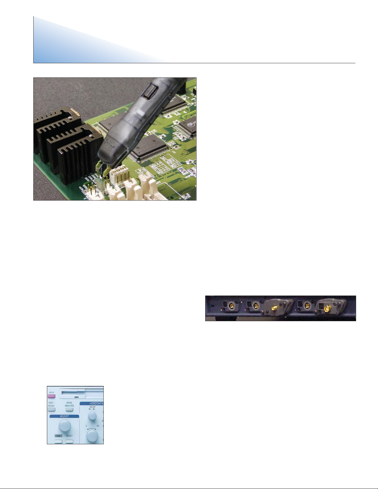
WaveLink high bandwidth differential probes let you capture head signals
with best signal to noise ratio.
2
DDA 5005A / DDA 50005A XXL
Disk Drive Analyzer
Page 3

Ver tical System
Analog Bandwidth @ 50 Ω (-3 dB) 5 GHz
Input Channels 4
Bandwidth Limiter 20 MHz; 200 MHz;1 GHz; 3 GHz; 4 GHz
Input Impedance 50 Ω ±1.5%
Input Coupling DC, GND
Maximum Input 2.5 Vrms; ±4 Vpeak
Ver tical Resolution 8 bits;up to 11 bits with enhanced resolution (ERES)
Sensitivity 2 mV–1 V/div fully variable; Full bandwidth at ≥ 10mV
Offset Range 2 mV–99 mV/div: ±750 mV;100 mV–1 V/div: ±4 V
Horizontal System
Timebases Internal timebase common to 4 input channels; An external clock may be applied at the Auxilary Input
Math and Zoom Traces 8 math/zoom traces
Clock Accuracy ≤ 1 ppm @ 0–40 degrees C.
Time Interpolator Resolution 1 ps
External Clock Frequency 2 GHz maximum, 50 Ω impedance
Roll Mode – Operating Range Time/div 500 ms–1000 s/div or sample rate < 100 kS/s max
Acquisition System
Single-Shot Sample Rate/Ch 10 GS/s
2 Channel Max 20 GS/s
Maximum Acquisition Points/Ch 100 Mpts/2 Ch, 50 Mpts/4 Ch
Acquisition Modes
Random Interleaved Sampling (RIS) 200 GS/s for repetitive signals: 20 ps/div–1 µs/div
Single-Shot For transient and repetitive signals:20 ps/div–10 s/div
Sequence 2–20,000 segments
Intersegment Time Typically 5 µs
Acquisition Processing
Averaging Summed averaging; Continuous averaging
Enhanced Resolution (ERES) From 8.5 to 11 bits vertical resolution
Envelope (Extrema) Envelope,floor, roof for up to 1 million sweeps
Triggering System
Modes Normal, Auto, Single, and Stop
Sources Any input channel, External, Ext x 10, Ext/10,or line; slope and level unique to each source (except line trigger)
Coupling Mode DC
Pre-trigger Delay 0–100% of horizontal time scale
Post-trigger Delay 0–10,000 divisions
Hold-off by Time or Events Up to 20 s or from 1 to 99 999 999 events
Internal Trigger Range ±5 div
Max Trigger Frequency 5 GHz with Edge Trigger; 750 MHz with SMART Trigger
External trigger input range Ext ±0.4; Ext x 10 ±0.04; Ext / 10 ±4 V
Automatic Setup
Auto Setup Automatically sets timebase, trigger, and sensitivity to display a wide range of repetitive signals
Ver tical Find Scale Automatically sets the vertical sensitivity and offset for the selected channels to display a waveform
with maximum dynamic range
Probes
Probes A variety of passive and active probes is optional
Probe System: ProLink with Probus Automatically detects and supports a variety of compatible probes; Supports ProLink SMA or
BNC input adapters
Scale Factors Automatically or manually selected depending on probe used
3
DDA 5005A / DDA 50005A XXL
Disk Drive Analyzer Specifications (continued)
Page 4

DDA 5005A / DDA 50005A XXL
Disk Drive Analyzer Specifications (continued)
Color Waveform Display
Type Color 10.4" flat-panel TFT-LCD with high resolution touch panel
Resolution SVGA; 800 x 600 pixels
Real-time Clock Dates, hours,minutes, seconds displayed with waveform
Number of Traces Display a maximum of eight traces.Simultaneously display channel, zoom, memory,and math traces
Grid Styles Single, Dual, Quad,Octal, XY, Single + XY,Dual + XY
Waveform Styles Sample dots joined or dots only
Analog Persistence Display
Analog and Color-Graded Persistence Variable saturation levels; stores each trace’s persistence data in memory
Persistence Selections Select Analog or color positive
Trace Selection Activate Analog Persistence on all or any combination of traces
Persistence Aging Time Select from 500 ms to infinity
Sweeps Displayed All accumulated or all accumulated with last trace highlighted
Zoom Expansion Traces
Display up to 4 Zoom and 4 Math/Zoom traces (8 Math/Zoom traces available with Master Analysis option)
Rapid Signal Processing
Processor Intel Pentium with MS Windows Platform
Processing Memory 512 Mbytes
Internal Waveform Memory
M1, M2,M3, M4 Internal Waveform Memory (Store full-length waveforms with 16 bits/data point)
Or store to any number of files limited only by data storage media
Setup Storage
Front Panel and Instrument Status Store to the internal hard drive, floppy drive, or to a USB connected peripheral device
Interface
Remote Control Full command set for all front panel controls and internal functions via GPIB or Ethernet
GPIB Port (Optional) Full control via IEEE – 488.2
Ethernet Port 10/100Base-T Ethernet interface
Floppy Drive Internal, DOS-format, 3.5" high-density
USB Ports Minimum of 2 USB ports supports Windows compatible devices
External Monitor Port Standard 15-pin D-Type SVGA-compatible
Parallel Port 1 standard
Auxiliary Output
Signal Types Select from calibrator or control signals output on front panel
Calibrator Signal 500 Hz – 5 MHz square wave or DC Level
0.0 to +0.5 Volts (Selectable) into 50 Ω
Control Signals Trigger ready, trigger out, pass/fail status
Auxiliary Input
Signal Types Select from External Trigger or External Clock input on front panel
General
Auto Calibration Ensures specified DC and timing accuracy is maintained for 1 year minimum
Power Requirements 100–120 V AC at 50/60/400 Hz; 200–240 V AC at 50/60 Hz; Power consumption: < 1 kVA , 940 Watts max
Physical Dimensions
Dimensions (HWD) 264 mm x 397 mm x 491 mm; 10.4" x 15.65" x 19.25" (height excludes feet)
Weight 18 kg; 39.5 lbs.
Shipping Weight 24 kg; 53 lbs.
Warranty and Service
3-year Warranty; calibration recommended annually.Optional service programs include extended warranty,
upgrades, and calibration services
4
Page 5

Math Tools
Display up to eight math function traces (F1–F8);The easy to use graphical
interface simplifies setup of up to two operations on each function
trace. Function traces can be chained together to perform math-on-math.
Pass/Fail
Test waveforms by comparing their shape to test templates,and
simultaneously check multiple parameters versus selectable parameter
or mask limits. Pass or fail conditions can initiate actions including
document::local or networked files, or e-mail the image of the failure,
save waveforms,or send a GPIB SRQ, or pulse to trigger another device.
Automated Disk Drive Measurements
Standard Automated Measurements
Advanced Drive Analysis
Advance Drive Analysis capabilities of the DDA 5005A include:
• Head Filter/ Equalizer Emulation
• Channel Emulation
• SAM Histograms
• Plot of SAM Values
• PES Runout Analysis
• Analog Compare
Additional waveshape analysis capabilities include:
• FFT capability includes: power averaging, power density, real and
imaginary components, and frequency domain parameters
• Parameter Math – add, subtract, multiply or divide two
different parameters
• User-definable parameter measurements
• User-definable math functions
amplitude
area
base
cycles
cycle std.deviation
cycle mean
cycle median
cycle rms
data
delay
duty cycle
duration
falltime
frequency
first
maximum
mean
minimum
+overshoot
–overshoot
peak-to-peak
period
risetime
rms
std. deviation
top
width
last
media
number of points
phase
time @ minimum (min)
time @ maximum (max)
∆ delay
∆ time @ level
∆ time @ level from
trigger
∆ time from clock
to data + (setup
time)
∆ time from clock to
data - (Hold time)
18 Histogram
Parmeters
absolute value
average (summed)
Average (continuous)
difference (-)
differentiate
enhanced resolution
(to 11 bits vertical)
envelope
exp (base e)
exp (base 10)
FFT
floor
identity
integrate
log (base e)
log (base 10)
negate
product (x)
ratio (/)
reciprocal (invert)
resample (deskew)
rescale (with units)
roof
sin x/x
square
square root
sum (+)
histogram
trend (datalog)
Auto-correlation
TAA
TAA+
TAAPW50
PW50+
PW50-
Resolution
Overwrite
lbase
lbsep
lmax
lmin
lnum
lpp
ltbe
ltbp
ltmn
ltmx
ltot
ltpt
lttp
ltut
NLTS
ACSN
msnr
rsnr
m_to_r
nbph
nbpw
Jitter measurement for parameters including:period, cycle-cycle,
frequency, and edge@lv, with JitterTrack of up to 200 edges.
FFT includes: power averaging, power density, real and imaginary
components,and frequency domain parameters.
DDA 5005A / DDA 50005A XXL
Disk Drive Analyzer Specifications
Basic Triggers
Edge/Slope/Line Triggers when signal meets slope and level condition
SMART Triggers
State or Edge Qualified Triggers on any input source only if a defined state or edge occurred on another
input source. Delay between sources is selectable by time or events
Dropout Triggers if signal drops out for longer than selected time between 2 ns and 20 s
Pattern Logic combination (AND,NAND, OR, NOR) of 5 inputs (4 channels and external trigger input)
Each source can be high, low, or don’t care
Trigger at start or end of the pattern
SMART Triggers with Exclusion Technology
Glitch Triggers on positive or negative glitches with widths selectable from 600 ps to 20 s or on intermittent faults
Signal or Pattern Width Triggers on positive or negative pulse widths selectable from 600 ps to 20 s or on intermittent faults
Signal or Pattern Interval Triggers on intervals selectable between 2 ns and 20 s
Disk Drive Triggers
Sector Triggers on the n’th sector pulse after index. Index and sector pulse polarity and sector pulse number are selectable
Servo Gate Triggers on the n’th servo gate after index and every m’th thereafter.Index and servo gate pulse polarity are selectable
PES Trigger Triggers on Position Error Signal (PES) exceeding an adjustable voltage window.Servo gate can be selected as qualifier
Read Gate Trigger Triggers on any read gate longer than an adjustable Sector ID filed length
5
Page 6

Ordering Information Product Code
DDA 5005A Four Channel Disk Drive Analyzer
5 GHz, 20 GS/s 2 Ch;10 GS/s Ch, Color DSO DDA 5005A
48 Mpts 2 Ch; 24 Mpts/Ch Standard
DDA 5005A XXL Four Channel Disk Drive Analyzer
5 GHz, 20 GS/s 2 Ch;10 GS/s Ch, Color DSO DDA 5005A XXL
100 Mpts 2 Ch; 50 Mpts/Ch Standard
Included with Standard Configuration
CD-ROM Drive
Floppy Disk Drive
LeCroy ProLink Adapter SMA and BNC
Optical 3-button Wheel Mouse-USB
Operators Manual; Quick Reference Guide; CD-ROM with OM/RCM
and Utility Software
Protective Front Cover
Remote Control Manual
Standard Commercial Calibration and Performance Certificate
Standard Ports; 10/100BaseT Ethernet,Parallel, SVGA Video Output, USB
3-Year Warranty
Hardware Options
LeCroy ProLink Adapter BNC LPA-BNC
WaveShape Analysis Packages
Digital Filter Package DFP2
Jitter and Timing Analysis Package JTA2
Serial Data Mask Testing Package SDM
Selected Accessories
2.5 GHz Active Voltage Probe HFP2500
7.5 GHz Passive Probe PP066
AntiVirus Software AV
Differential Probe AP034
1 MΩ Adapter includes PP005A Passive Probe
AP-1M
Keyboard KYBD-1
LeCroy ProLink Adapter BNC LPA-BNC
LeCroy ProLink Adapter BNC Kit of 5 LPA-BNC-Kit
Oscilloscope Cart OC1021
Oscilloscope Cart with Additional Shelf and Drawer OC1024
Rackmount Kit - 25" Slide RMA-25
Rackmount Kit - 30" Slide RMA-30
WaveLink 6 GHz Differential Probe D600AT with D600
WaveLink 4 GHz Differential Probe D300AT with D300
Warranty and Calibration
MIL STD Calibration Certificate DDA-CCMIL
NIST Traceable Calibration Certificate DDA-CCNIST
5-Year Warranty (at time of purchase) DDA-W5
5-Year Warranty and NIST Calibration (at time of purchase) DDA-T5
5 Annual NIST Calibrations DDA-C5
1-Year Extended Warranty DDA-EW
2-Year Extended Warranty DDA-EW2
Sales and Service
Throughout
the World
Corpo rate
Headquarters
700 Chestnut Ridge Road
Chestnut Ridge, NY 10977
USA
www.lecroy.com
LeCroy Sales Offices:
China: Beijing
Phone (86) 10 8526 1618
Fax (86) 10 8526 1619
France: Les Ulis
Phone (33) 1 6918 8320
Fax (33) 1 6907 4042
Germany: Heidelberg
Phone (49) 6221 827 00
Fax (49) 6221 834 655
Hong Kong
Phone (852) 2834 5630
Fax (852) 2834 9893
Italy: Venice
Phone (39) 041 599 7011
Fax (39) 041 456 9542
Japan: Osaka
Phone (81) 6 6396 0961
Fax (81) 6 6396 0962
Japan: Tokyo
Phone (81) 3 3376 9400
Fax (81) 3 3376 9587
Korea: Seoul
Phone (82) 2 3452 0400
Fax (82) 2 3452 0490
Singapore
Phone (65) 6442 4880
Fax (65) 6442 7811
Sweden: Stockholm
Phone (46) 8 580 143 45
Fax (46) 8 580 143 45
Switzerland: Geneva
Phone (41) 22 719 2228 (North)
Phone (41) 22 719 2175 (South)
Fax (41) 22 719 2230
U.K.: Abingdon
Phone (44) 1 235 536 973
Fax (44) 1 235 528 796
U.S.A.: Chestnut Ridge
Phone (1) 845 578 6020
Fax (1) 845 578 5985
DS DDA5005A
PDF 3/05
© 2004 by LeCroy Corporation. All rights reser ved.
LeCroy,ActiveDSO, ProBus, SMART Trigger, JitterTrack, WavePro,WaveMaster, and Waverunner are registered trademarks of LeCroy
Corporation. Information in this publication supersedes all earlier versions. Specifications subject to change without notice.
 Loading...