

Page 1
LeCroy
DA18000
Differential Amplifier
Instruction Manual
December 2006
Page 2
LeCroy Corporation
700 Chestnut Ridge Road
Chestnut Ridge, NY 10977-6499
Tel: (845) 578-6020, Fax: (845) 578-5985
Internet: www.lecroy.com
Warr anty
LeCroy warrants this oscilloscope accessory for normal use and operation within specification for a
period of one year from the date of shipment. Spare parts, replacement parts and repairs are warranted for 90 days.
In exercising its warranty, LeCroy, at its option, will either repair or replace any assembly returned
within its warranty period to the Customer Service Department or an authorized service center.
However, this will be done only if the product is determined by LeCroy’s examination to be defective
due to workmanship or materials, and the defect is not caused by misuse, neglect, accident, abnormal conditions of operation, or damage resulting from attempted repair or modifications by a nonauthorized service facility.
The customer will be responsible for the transportation and insurance charges for the return of products to the service facility. LeCroy will return all products under warranty with transportation charges
prepaid
This warranty replaces all other warranties, expressed or implied, including but not limited to any
implied warranty of merchantability, fitness or adequacy for any particular purposes or use. LeCroy
shall not be liable for any special, incidental, or consequential damages, whether in contract or otherwise.
© 2006 by LeCroy Corporation. All rights reserved.
LeCroy, ActiveDSO, WaveLink, JitterTrack, WavePro, WaveMaster, WaveSurfer, WaveJet, and
Waverunner are registered trademarks of LeCroy Corporation. Other product or brand
names are trademarks or requested trademarks of their respective holders. Information in
this publication supersedes all earlier versions. Specifications subject to change without
notice.
Manufactured under an
ISO 9000 Registered
Quality Management System
Visit www.lecroy.com to view the
certificate.
DA18000-OM-E Rev A
914715-00 Rev A
This electronic product is subject to disposal and recycling
regulations that vary by country
and region. Many countries prohibit the disposal of waste electronic equipment in standard
waste receptacles.
For more information about
proper disposal and recycling of
your LeCroy product, please
visit www.lecroy.com/recycle.
Page 3
DECLARATION OF CONFORMITY
according to ISO/IEC Guide 22 and EN 45014:1998
Manufacturer’s Name: LeCroy Corporation
Manufacturer’s Address: 700 Chestnut Ridge Road
herewith declare that
Product(s) Name: Differential Amplifier
Model Number(s): DA18000
including all their options are in conformity with the provisions of the following EC directive(s), including the latest
amendments, and with national legislation implementing these directives:
and that conformity with Council Directive 73/23/EEC is based on
EN 61010-031: 2002 Safety requirements for electrical equipment for measurement, con-
and that conformity with Council Directive 89/336/EEC is based on
EN 61326/A3:2003 EMC requirements for electrical equipment for measurement, con-
Emissions EN 55011/A2:2002 Radiated Emissions
Immunity: EN 61000-4-2/A2:2001 Electrostatic Discharge
Chestnut Ridge, NY 10977
USA
73/23/EEC Low Voltage Directive
89/336/EEC EMC Directive
trol and laboratory use
Part 031: Safety requirements for hand -held amplifier assemblies for
electrical measurement and test
trol and laboratory use
EN 61000-4-3/A1:2003 RF Radiated Electromagnetic Field
By: Scott Bausback European Contact:
Chief Operating Officer Your local LeCroy Sales Office or
Place: LeCroy Corporation LeCroy Europe GmbH
700 Chestnut Ridge Road Waldhofer Str. 104
Chestnut Ridge, NY 10977 D-69123 Heidelberg
USA Germany
Date: June 12, 2006 Tel: (49) 6221 82700
Warning: This is a Class A product. In a domestic environment this product may cause radio interference, in
which case the user may be required to take adequate measures.
DA18000-OM-E Rev A iii
Fax: (49) 6221 834655
Page 4

BLANK PAGE
iv DA18000-OM-E Rev A
Page 5

Table of Contents
Safety Information ............................................................................. 1-1
SAFETY SYMBOLS ...........................................................................................1-1
OPERATOR SAFETY ........................................................................................1-1
OPERATING ENVIRONMENT ..........................................................................1-2
Overview ............................................................................................. 2-1
DESCRIPTION ..................................................................................................2-1
APPLICATIONS .................................................................................................2-1
STANDARD ACCESSORIES ............................................................................2-1
Components and Accessories ......................................................... 3-1
STANDARD ACCESSORIES ............................................................................3-1
2.92 mm Input Cables ................................................................................3-1
2.92 mm÷2 Attenuator ................................................................................3-1
Operation ............................................................................................ 4-1
HANDLING THE AMPLIFIER ............................................................................4-1
2.92 MM CONNECTORS ..................................................................................4-1
COMPATIBILITY ................................................................................................4-1
CONNECTING THE AMPLIFIER TO A LECROY SERIAL DATA ANALYZER .4-1
AUTOCOLOR ID ................................................................................................4-2
OPERATION WITH THE SDA 18000 ................................................................4-2
CONNECTING THE AMPLIFIER TO THE TEST CIRCUIT ...............................4-3
2.92 mm Input Cables ................................................................................4-3
USE OF DC ÷2 ATTENUATOR .........................................................................4-4
DYNAMIC RANGE .............................................................................................4-4
Care and Maintenance ....................................................................... 5-1
CLEANING ........................................................................................................5-1
SERVICE STRATEGY .......................................................................................5-1
RETURNING AN AMPLIFIER FOR CALIBRATION OR SERVICE ...................5-1
RETURNING AN AMPLIFIER TO A DIFFERENT COUNTRY ..........................5-2
REPLACEMENT PARTS ...................................................................................5-2
Reference Information ....................................................................... 6-1
DIFFERENTIAL MODE AND COMMON MODE ...............................................6-1
DIFFERENTIAL MODE RANGE AND COMMON MODE RANGE ....................6-1
COMMON MODE REJECTION RATIO .............................................................6-2
Performance Verification .................................................................. 7-1
INTRODUCTION ...............................................................................................7-1
TEST EQUIPMENT REQUIRED .......................................................................7-1
PRELIMINARY PROCEDURE ...........................................................................7-2
DA18000-OM-E Rev A v
Page 6

DA18000 Differential Amplifier
VERIFICATION PROCEDURE ......................................................................... 7-2
1. Rise Time (20-80%) ............................................................................... 7-2
2. Voltage Gain Accuracy............................................................................ 7-5
Specifications ..................................................................................... 8-1
NOMINAL CHARACTERISTICS ....................................................................... 8-1
General ...................................................................................................... 8-1
WARRANTED CHARACTERISTICS ................................................................ 8-1
TYPICAL CHARACTERISTICS ........................................................................ 8-2
ENVIRONMENTAL CHARACTERISTICS ........................................................ 8-3
PHYSICAL CHARACTERISTICS ...................................................................... 8-3
COMPLIANCE AND CERTIFICATIONS ........................................................... 8-4
EC Declaration of Conformity ..................................................................... 8-4
Appendix A ......................................................................................... A-1
PERFORMANCE VERIFICATION TEST RECORD .........................................A-1
ITEMS TESTED ................................................................................................A-1
EQUIPMENT USED ..........................................................................................A-1
TEST RECORD .................................................................................................A-1
vi DA18000-OM-E Rev A
Page 7
Safety Information
1Safety Information
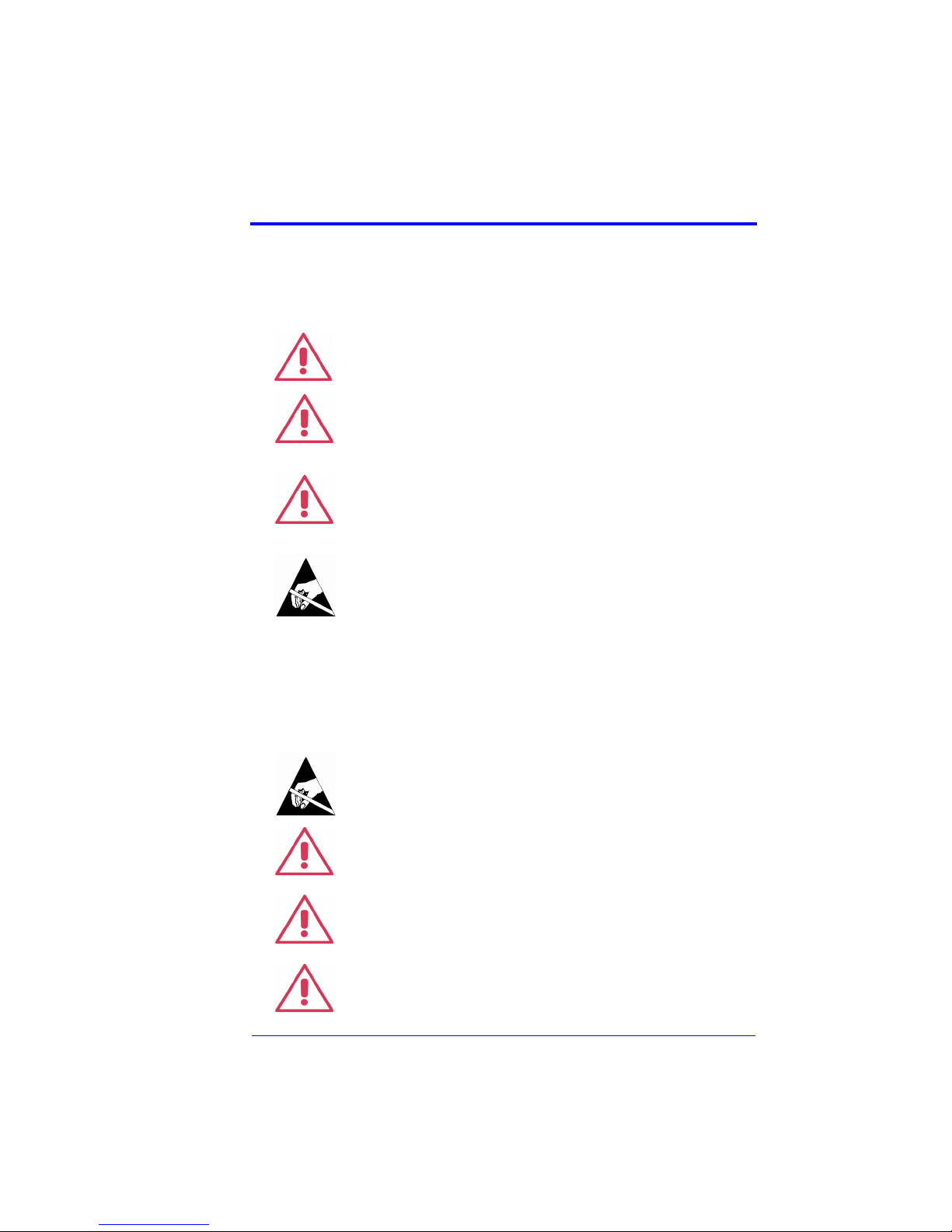
SAFETY SYMBOLS
The following symbols appear on the DA18000 Differential Amplifier or in this manual and
alert the customer to important safety considerations.
Refer to the accompanying information or document to protect against
personal injury or damage to the instrument.
The CAUTION sign indicates a potential hazard. It calls attention to a
procedure, practice or condition, which, if not followed, could possibly
cause damage to the equipment. If a CAUTION is indicated, do not pro-
CAUTION
WARNING
OPERATOR SAFETY
To avoid personal injury and to prevent damage to the probe or any products connected to it,
review the following safety precautions. To avoid potential hazards, use the probe only as
specified.
ceed until its conditions are fully understood and met.
The WARNING sign indicates a potential hazard. It calls attention to a
procedure, practice or condition which, if not followed, could possibly
cause bodily injury or death. If a WARNING is indicated, do not proceed
until its conditions are fully understood and met.
The ESD sign indicates a potential hazard. It calls attention to the susceptibility of the equipment to Electrostatic Discharge (ESD) induced
damage if anti-static measures are not taken.
To avoid damage to the amplifier or personal injury, comply with the
following:
ESD Sensitive: The amplifier tips of the DA18000 amplifier are sensitive to electrostatic discharge (ESD). To avoid causing damage to the
amplifier, always follow anti-static procedures (wear wrist strap, etc.)
when using or handling the amplifier.
Connect amplifier to the measurement instrument before connecting
the probe test leads to a circuit/signal being tested.
CAUTION
Using the amplifier and/or the oscilloscope it is connected to in a manner other than that specified may impair their protection mechanisms.
CAUTION
Do not apply a voltage to any input that exceeds the maximum rating of
that input. (Section 9, Specifications).
WARNING
DA18000-OM-E Rev A 1-1
Page 8
DA18000 Differential Amplifier
Handle the probe with care as it has sharp tips that may cause bodily
injury if not handled properly.
WARNING
Do not use the amplifier in wet or explosive atmospheres.
WARNING
Do not use the amplifier if any part is damaged. All maintenance should
be referred to qualified service personnel.
CAUTION
OPERATING ENVIRONMENT
The DA18000 Differential Amplifier is intended for indoor use and should be operated in a
clean, dry environment.
The design of the differential amplifier has been verified to conform to EN 61010-031 safety
standard per the following limits:
• Installation (Overvoltage) Category I: Refers to signal level which is applicable for
equipment measuring terminals that are connected to source circuits in which
measures are taken to limit transient voltages to an appropriate low level.
• Pollution Degree 2: Refers to an operating environment where normally only dry
non-conductive pollution occurs. Occasionally a temporary conductivity caused by
condensation must be expected.
§ § §
1-2 DA18000-OM-E Rev A
Page 9
Overview
2Overview
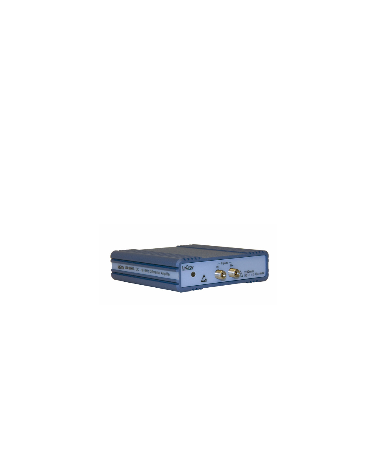
DESCRIPTION
The DA18000 Differential Amplifier is a very high bandwidth differential amplifier with 50 Ω
inputs and high common mode rejection, and is designed to be used exclusively with the
SDA 18000 Serial Data Analyzer.
The amplifier contains common circuitry such as power supply, communication and control
and AutoColor ID. The DA18000 amplifier utilizes digital filtering to improve the system frequency response. The response is corrected through the use of digital filters which are specifically tailored through calibration to optimize the frequency flatness of the amplifier. This
provides the highest fidelity in eye pattern measurements.
Certificate of Calibration is supplied with each amplifier indicating that the system will meet
the specifications with those components listed in the Certificate.
ESD Sensitive: The inputs of the DA18000 amplifier are sensitive to
Electrostatic Discharge (ESD). To avoid causing damage to the amplifier, always follow anti-static procedures (wear wrist strap, etc.) when
using or handling the 2.92 mm connectors.
APPLICATIONS
The DA18000 amplifier is ideally suited for acquiring differential signals common in high
speed serial data applications with fine pitch ICs and high lead count where high speed,
minimal loading and accurate jitter measurement are required.
• System Designers:
Designing systems using standard and ASIC components Use simulators and correlate
with lab measurements
• IC Designers:
Characterize new chip design
• Manufacturers of servers, PC Motherboards, Data routers, Disk drives
• High-speed SERDES
STANDARD ACCESSORIES
• Matched 2.92 mm Input Cables (1 pair)
• 2.92 mm 6 dB attenuators (2)
• SAC-01 Soft Accessory Case with insert
• ESD Dissipating Wrist Strap
• DA18000 Instruction Manual
• Certificate of Calibration
DA18000-OM-E Rev A 2-1
§ § §
Page 10

DA18000 Differential Amplifier
BLANK PAGE
2-2 DA18000-OM-E Rev A
Page 11
Components and Accessories
3Components and Accessories
STANDARD ACCESSORIES
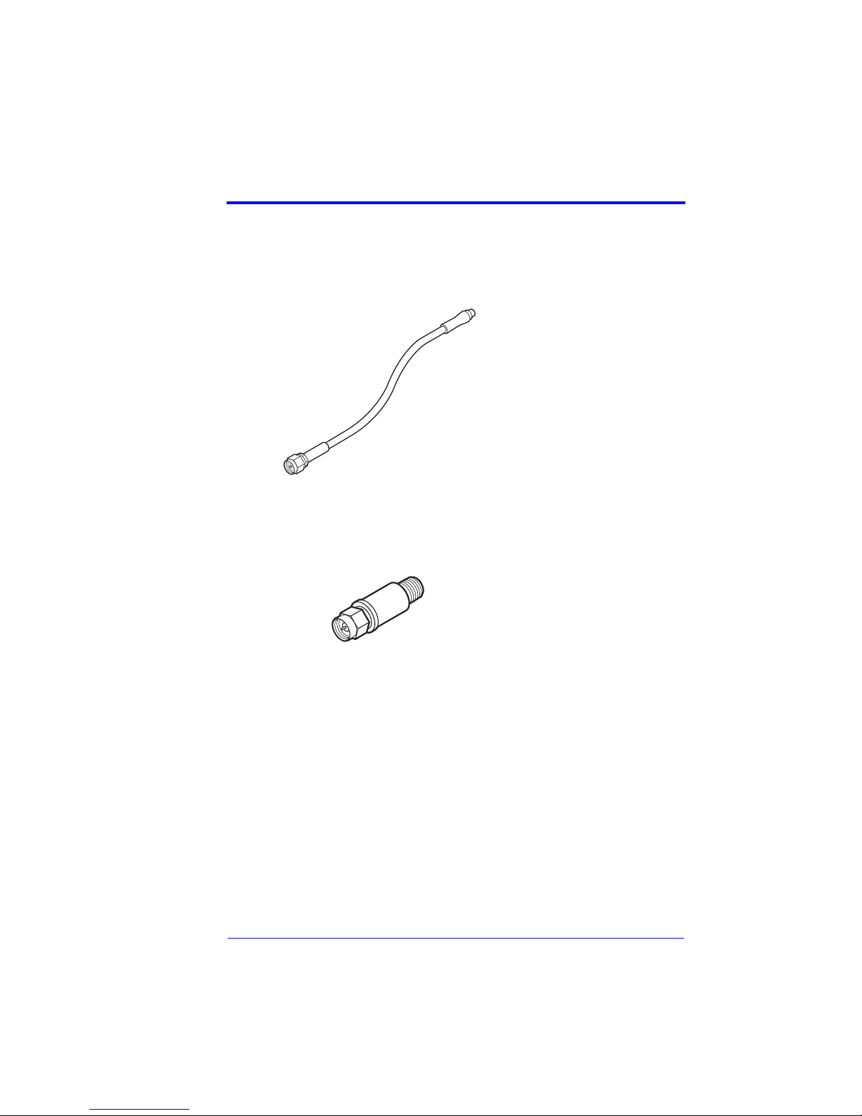
2.92 mm Input Cables
2.92 mm ÷2 Attenuator
A matched pair of 50 Ω
2.92 mm Input Cable is provided for direct cable connection to female 2.92 mm
connectors of the amplifier.
The 2.92 mm attenuator can
be used to extend the differential mode range or to improve
the VSWR by reducing reflections.
DA18000-OM-E Rev A 3-1
§ § §
Page 12

DA18000 Differential Amplifier
BLANK PAGE
3-2 DA18000-OM-E Rev A
Page 13

Operation
4Operation
HANDLING THE AMPLIFIER
The DA18000 Differential Amplifier is a precision test instrument; exercise care when handling and storing the amplifier. Always handle the amplifier by the body. Avoid putting excessive strain on the attached cables or exposing the cables to sharp bends.
ESD Sensitive: The inputs of the DA18000 amplifier are sensitive to
Electrostatic Discharge (ESD). To avoid causing damage to the amplifier, always follow anti-static procedures (wear wrist strap, etc.) when
connecting cables to the input.
2.92 MM CONNECTORS
The 2.92 mm connector of the DA18000 amplifier is a precision coaxial connector that operates up to 40 GHz. It is compatible with SMA, WSMA and 3.5 mm connectors.
To avoid misalignment of the male pin to the female contact, the male pin of the 2.92 mm
connector is made shorter than the SMA or 3.5 mm connector pins. This way the outer housing is properly aligned prior to mating of the center conductors. Because of the new design,
the insertion force has been reduced from about 27 N in SMA and 3.5 mm connectors to
about 2.3 N with the 2.92 mm design. 2.92 mm connectors can be tightened to the same
torque specification as is used for type SMA, without damage.
When connecting SMA or 3.5 mm connectors, always align the male and female
parts before insertion to prevent damage to the female center connector.
2.92 mm connectors use air for the dielectric, as opposed to PTFE resin in type SMA. Foreign material such as excessive dust can enter the dielectric pocket and degrade the high
frequency performance. Should this occur, remove the foreign material, using a jet of compressed air or gas. Disposable cans of compressed gas for dusting purposes are readily
available from photo or electronic equipment suppliers.
Note
Never insert an object into the connector in attempting to clean it. The
center contact can be easily bent out of position, destroying the
connector.
CAUTION
COMPATIBILITY
The DA18000 Differential Amplifier is designed to be used exclusively with the SDA 18000
Serial data Analyzer. However it includes frequency compensation data compatible with
lower BW WaveMaster, SDA, and DDA 5005 oscilloscopes.
CONNECTING THE AMPLIFIER TO A LECROY SERIAL DATA
ANALYZER
The DA18000 amplifier has been designed for exclusive use with the SDA 18000 Serial
Data Analyzer.
For optimum performance and full bandwidth always connect the amplifier only to channel 1
of the SDA 18000 analyzer.
DA18000-OM-E Rev A 4-1
Page 14

DA18000 Differential Amplifier
To attach the amplifier to the LeCroy oscilloscope, align the interface connector with the
input connector and push the interface toward the oscilloscope.
A click will be heard when the amplifier’s interface latches to the oscilloscope. This amplifier
also uses the thumb screws to secure the interface to the oscilloscope.
Thumb screws should be tightened finger tight only. Use of pliers or
another tool may overtighten the screws, resulting in damage to the
oscilloscope.
CAUTION
To remove the DA18000 from the LeCroy oscilloscope, move the amplifier up and down
while pulling gently till a loud snap is heard indicating that the amplifier is unlatched from the
oscilloscope.
AUTOCOLOR ID
When the amplifier is connected to a SDA 18000, the LED will illuminate in the default color
of the channel to which the amplifier is connected.
OPERATION WITH THE SDA 18000
When the amplifier’s output connector is attached to the SDA 18000 oscilloscope’s input
connector, the oscilloscope will recognize the amplifier and activate the vertical channel
functions in the user interface. Figure 4-4. Refer to your oscilloscope’s instruction manual for
operations of the oscilloscope.
4-2 DA18000-OM-E Rev A
Figure 4-1. Vertical Menu
Page 15

Operation
Control through the oscilloscope’s interface can be found in the screen menu of the channel
to which the amplifier is connected.
Touching the tab indicating the attached amplifier (in this case DA18000) will activate the
amplifier menu screen. Figure 4-5.
The amplifier information frame shows the characteristics of the amplifier only.
In some applications it may be desirable to turn the amplifier’s AutoColor ID OFF or ON with
touching the Led On frame.
Figure 4-2. Probe menu
CONNECTING THE AMPLIFIER TO THE TEST CIRCUIT
For all modules and interconnect leads, positive voltages applied to the + input relative to
the – input will deflect the oscilloscope trace towards the top of the screen.
2.92 mm Input Cables
The 2.92 mm Interconnect System has been designed to connect directly to female 2.92 mm
connectors as well as to the higher performance 3.5 mm and 2.92 mm female connectors.
The Interconnect Cable connects to the amplifier and the matched pair of SMA Cable connect to the Interconnect Lead.
The connector should be tightnened to a torque of 0.06 Nm (8 in.-oz.).
Note
The 2.92 mm Input Cables are supplied as a matched pair. Individual cables should
not be interchanged between amplifiers.
DA18000-OM-E Rev A 4-3
Page 16

DA18000 Differential Amplifier
USE OF DC ÷2 ATTENUATOR
The ÷2 attenuator should be used when the common mode or differential voltage of the circuit under test is unknown or exceeds the maximum voltage specified. (See section 9, Specifications). The use of the attenuator will also reduce the reflections, thus improving the
VSWR.
The DA18000 amplifier has no method to detect the presence or absence of the attenuator.
To maintain correct vertical scale factor and amplitude measurement results, you must
inform the oscilloscope when the attenuator is being used. This is done in the Vertical
Adjust → DA18000 control dialog for the channel that the amplifier is connected to.
DYNAMIC RANGE
The DA18000 amplifier has no gain or attenuation control. The system gain is fixed at x1.
Exceeding the common mode range may introduce distortion to the output signal. Use of the
÷2 attenuators will increase the differential mode range; however, due to power limitations,
they will not increase the common mode range.
There are two common mode voltages:
±10 V without a ÷2 attenuator
7 V
with a ÷2 attenuator
rms
§ § §
4-4 DA18000-OM-E Rev A
Page 17

Care and Maintenance
5Care and Maintenance
CLEANING
The exterior of the amplifier and cable should be cleaned using a soft cloth only moistened
with water or isopropyl alcohol. The use of abrasive agents, strong detergents or other solvents may damage the exterior of the amplifier.
CAUTION
The amplifier case is not sealed and should never be immersed in
any fluid.
SERVICE STRATEGY
Defective amplifiers must be returned to a LeCroy service facility for diagnosis and repair or
replacement. A defective product under warranty will be repaired or replaced.
RETURNING AN AMPLIFIER FOR CALIBRATION OR SERVICE
Procedure for returning a product for calibration or service:
Contact your local LeCroy sales representative to find out where to return the product. All
returned products should be identified by model number and serial number. Provide your
name and contact number and if possible describe the defect or failure. In case of products
returned to the factory, a Return Authorization Number (RAN) should be used. The RAN can
be established by contacting your nearest LeCroy sales office, representative, or the North
America Customer Care Center.
Return shipment should be prepaid. LeCroy cannot accept COD or Collect Return shipments. We recommend air-freighting.
Note
It is important that the RAN be clearly shown on the outside of the shipping package
for prompt redirection to the appropriate department.
1. Contact your local LeCroy sales or service representative to obtain a Return Authorization Number.
2. Remove all accessories from the amplifier. Do not include the manual. If you need to
return a DA18000 system, do include all Interconnect Leads.
3. Pack the probe in its case, surrounded by the original packing material (or equivalent)
and box.
4. Label the case with a tag containing:
•RAN
• Name and address of the owner
• Product model and serial number
• Description of failure
5. Package the probe case in a cardboard shipping box with adequate padding to avoid
damage in transit.
DA18000-OM-E Rev A 5-1
Page 18

DA18000 Differential Amplifier
6. Mark the outside of the box with the shipping address given to you by the LeCroy representative; be sure to add the following:
• ATTN: <RAN assigned by the LeCroy representative>
•FRAGILE
7. Insure the item for the replacement cost of the product.
8. Ship the package to the appropriate address.
RETURNING AN AMPLIFIER TO A DIFFERENT COUNTRY
In order to avoid customs duty for purchase price of a new amplifier or accessory, when your
probe is returned for service, please use the following procedure.
In addition to the items mentioned above in ‘Returning a probe for calibration or service’,
you’ll need to mark shipments returned for service as a ‘Return of US manufactured goods
for warranty repair/recalibration’. If there is a cost involved in the service, put the cost of the
service in the value column and the original value of the product at time of purchase in the
body of the invoice marked ‘For insurance purposes only’. Be very specific as to the reason
for shipment. Duties may have to be paid on the value of the service.
REPLACEMENT PARTS
The amplifier accessories and other common parts can be ordered through the regional customer care centers. Refer to table 5-1 for LeCroy part numbers.
Table 5-1. Replaceable Parts List
Item LeCroy P/N
Type ‘K’ Lead PK18000-1 1
÷2 Attenuator 1
DA18000 Instruction Manual DA18000-OM-E 1
§ § §
Replacement
Quantity
5-2 DA18000-OM-E Rev A
Page 19

Reference Information
6Reference Information
DIFFERENTIAL MODE AND COMMON MODE
Differential amplifiers sense the voltage difference which appears between the + input and –
input. This voltage is referred to as the Differential Mode or Normal Mode voltage. The voltage component which is referenced to earth and is identical on both inputs is rejected by the
amplifier. This voltage is referred to as the Common Mode voltage and can be expressed as:
V
+input
--------------------------------------
=
V
CM
+
2
V
–input
DIFFERENTIAL MODE RANGE AND COMMON MODE RANGE
Differential Mode range is the maximum signal which can be applied between the + and inputs without overloading the amplifier/amplifier, which otherwise would result in clipping or
distorting of the waveform measured by the oscilloscope.
The Common Mode Range is the maximum voltage with respect to earth ground which can
be applied to either input. Exceeding the common mode range can result in unpredictable
measurements. Because the Common Mode signal is normally rejected and not displayed
on the oscilloscope, the user needs to be careful to avoid accidentally exceeding the common mode range.
Because the input signal of a differential amplifier is not referenced to ground, the concept of
"V
" versus “V
peak
With a ground referenced signal, V
signal will have with respect to ground. In a differential system, there is no ground reference.
Therefore the Differential Mode Range refers to the maximum instantaneous amplitude of
the signal difference between the positive input and the negative input. Since most amplifiers have symmetrical bipolar inputs, the value is generally expressed as an absolute value,
and can have either polarity.
For example, an amplifier with a differential mode rating of ±1 V can have a maximum voltage difference appearing at any instant in time of 1 V between the inputs. The polarity could
be either positive or negative. This does not imply that the number can be doubled to 2 volts,
however. For clarity, consider the following table of absolute voltages applied to the inputs of
a differential amplifier that has a differential mode range or ±1 V and a common mode range
of ±5 V:
peak-peak
” may be confusing.
is the maximum instantaneous voltage amplitude the
peak
DA18000-OM-E Rev A 6-1
Page 20

DA18000 Differential Amplifier
Voltage on +
input to ground
+1.5 V +0.8 V +0.7 V OK: within ±1 V
-1.5 V -0.8 V -0.7 V OK: within ±1 V
+0.8 V -0.1V +0.9 V OK: within ±1 V
+1.0 V -1.0 V +2.0 V Out of range:
+6.5 V +6.0 V 0.5 V Exceeds ±5 V
1.5 V
Some amplitudes are specified as "peak to peak." The differential amplifier peak-to-peak
range will be twice the peak differential mode range specification as, at any instant in time,
the maximum voltage amplitude signal would be one-half of the peak-to-peak value.
In a balanced differential system, the signal on each output will be an inverted copy of the
other input. For example, an LVDS system may have a pair of outputs, each of which has a
voltage swing of 0 to +370 mV. A logic 1 would be represented when the + output is at
+370 mV, while the - output is at 0 V. A logic zero would be the opposite polarity: the + output
at 0 V and the - output at +370 mV. Note that even though both outputs swing 370 mV, the
maximum difference voltage between them at any instant is still within ±370 mV. So this signal could be measured with a differential amplifier that has a differential mode range of ±400
mV.
sine Ground 0.75 Vpeak OK: within ±1 V
pk-pk
Voltage on -
input to ground
Difference Comment
range
range
range
exceeds ±1 V
common mode
range
range
COMMON MODE REJECTION RATIO
The ideal differential amplifier/amplifier would sense and amplify only the differential mode
voltage component and reject all of the common mode voltage component. Real differential
amplifiers are not perfect and a small portion of the common mode voltage component
appears at the output. Common Mode Rejection Ratio (CMRR) is the measure of how much
the amplifier rejects the common mode voltage component. CMRR is equal to the differential
mode gain (or normal gain) divided by the common mode gain. Common mode gain is equal
to the output voltage divided by the input voltage when both inputs are driven by only the
common mode signal. CMRR can be expressed as a ratio (e.g. 10,000:1) or implicitly in dB
(e.g. 80 dB). Higher numbers indicate greater rejection (better performance).
The first order term which determines the CMRR is the relative gain matching between the +
and – input paths. To obtain high CMRR values, the input attenuators in a differential amplifier are precisely matched to each other. The matching includes the DC attenuation as well
as the capacitance which determines the AC attenuation. As the frequency of the common
6-2 DA18000-OM-E Rev A
Page 21

Reference Information
mode component increases, the effects of stray parasitic capacitance and inductance in
determining the AC component becomes more pronounced. The CMRR becomes smaller
as the frequency increases. Hence the CMRR is usually specified in a graph of CMRR versus common mode frequency.
The common mode frequency in these graphs is assumed to be sinusoidal. In real life applications, the common mode signal is seldom a pure sine wave. Signals with pulse wave
shapes contain frequency components much higher than the repetition rate may suggests.
As such, it is very difficult to predict actual performance in the application for CMRR versus
frequency graphs. The practical application of these graphs is to compare the relative common mode rejection performance between different probes and amplifiers.
§ § §
DA18000-OM-E Rev A 6-3
Page 22

DA18000 Differential Amplifier
BLANK PAGE
6-4 DA18000-OM-E Rev A
Page 23

Performance Verification
7Performance Verification
INTRODUCTION
This procedure can be used to verify the warranted characteristics of the DA18000 Differential Amplifier.
The recommended calibration interval for this amplifier is one year. Test results can be
recorded on a photocopy of the Test Record provided in Appendix A.
Performance Verification can be completed without removing any covers or exposing the
user to hazardous voltages. No adjustments are provided.
In the unlikely event that the amplifier should fail the performance verification, it can be sent
back to the local service center or the factory. For information on returning the amplifier refer
to Section 5, Care and Maintenance.
This procedure tests the DA18000 for the following warranted specification:
•Rise time
• Voltage Gain Accuracy
TEST EQUIPMENT REQUIRED
Table 7-1 lists the test equipment and accessories, or their equivalents, that are required for
performance verification of the DA18000 Differential Amplifier.
This procedure has been developed to minimize the number of parameters required to be
calibrated in the test instrumentation.
Only the parameters listed in boldface in the “Minimum Requirements” column must be calibrated to the accuracy indicated.
Because the input and output connector types may vary on different brands and models of
test instruments, additional adapters or cables may be required.
Table 7-1. List of Required Equipment
Description Minimum Requirements
Oscilloscope, High BW SDA 18000 LeCroy: SDA 18000
Step Generator, Differential Differential output with
Attenuator, 2 ea. 6 dB, female-female,
2.92 mm coaxial cable,
2 ea.
Connector Saver female-female, 2.92 mm Supplied with ST-20
DA18000-OM-E Rev A 7-1
Test Equipment
Examples
LeCroy WaveExpert
deskew capability
T
≤ 20 ps
r
≈ 200 mV
V
out
oscilloscope with two ST-
20 TDR sampling
modules
Supplied with DA18000
2.92 mm
male-male, 2.92 mm, 50 Ω Supplied with DA18000
Page 24

DA18000 Differential Amplifier
Table 7-1. List of Required Equipment (Continued)
Description Minimum Requirements
Torque Wrench 8 in.-lbs. LeCroy: TW-8
Test Equipment
Examples
PRELIMINARY PROCEDURE
1. Allow at least 20 minutes warm-up time for the DA18000 Differential Amplifier and test
equipment before performing the Verification Procedure.
2. Turn on the other test equipment and allow these to warm up for the time recommended by the manufacturer.
3. While the instruments are reaching operating temperature, make a photocopy of the
Performance Verification Test Record (located in Appendix A), and fill in the necessary
data.
The warranted characteristics of the DA18000 Differential Amplifier are valid at any temperature within the Environmental Characteristics listed in “Specifications.” However, some of
the other test equipment used to verify the performance may have environmental limitations
required to meet the accuracy requirements needed for the procedure. Be sure that the
ambient conditions meet the requirements of all the test instruments used in the procedure.
VERIFICATION PROCEDURE
1. Rise Time (20-80%)
Measuring the amplifier’s rise time cannot be done directly; it has to be performed in an indirect way. First you have to measure the rise time of the source, i.e., the rise time of the pulse
generator (TDRs) and the oscilloscope. Second, measure the rise time of the system: pulse
generator, amplifier, and oscilloscope. The rise time of the amplifier alone can then be determined from these two measurements.
ESD Sensitive: The inputs of the DA18000 amplifier as well as those of
the oscilloscopes are sensitive to Electrostatic Discharge (ESD). To avoid
causing damage to the equipment, always follow anti-static procedures
(wear wrist strap, etc.) when working with these instruments.
a. Install the two ST-20 TDRs in Ch 1 and Ch 2 of the WE 9000 oscilloscope.
b. To prevent accidental discharge of any accumulated charge in the coaxial cables,
attach a ÷2 attenuator to one end of each of the two 2.92 mm coaxial cables before
connecting the cables to the oscilloscope. This will provide a discharge path.
c. Then connect the other end of each cable to the connector saver at the outputs of the
ST-20 TDRs.
When fastening an SMA or 2.92 mm connector, always use the torque
wrench to tighten the connector.
7-2 DA18000-OM-E Rev A
Page 25

Performance Verification
d. Remove the ÷2 attenuator from the coaxial cables.
e. From the menu bar, select Timebase (Figure 7-1).
f. Set the WE 9000 to output a differential step. This sampling oscilloscope is only used
to provide power to the ST-20 TDR pulse generators
g. Initialize the TDR by touching the TDR Main tab.
Figure 7-1. Timebase Menu
h. Connect the ST-20 TDR coaxial cable from Channel 1 of the WE 9000 via the LPA–K
adapter to Channel 1 of the SDA 18000. Be sure to properly torque all connectors
(8 in.-lbs.).
i. Set the SDA 18000 to Channel 1 and the timebase to 500 ps/div and 60 GS/s. Set the
scope to trigger on Channel 1, and edge triggering to positive slope.
j. Set math trace F1 to the Ptrace mean of Channel 1 (Figure 7-2).
DA18000-OM-E Rev A 7-3
Page 26

DA18000 Differential Amplifier
Figure 7-2. Math Menu Setup
k. Set a measurement function to measure Rise 20-80% (Figure 7-3).
7-4 DA18000-OM-E Rev A
Figure 7-3. Measure Menu Setup
Page 27

Performance Verification
l. Record the measured 20-80% rise time as “Source rise time” (t
Record (Figure 7-4).
Only the positive edge is measured. The difference in rise time between the positive
edge and the negative edge of the STD-20 TDR is less than 1 ps.
m. To measure the amplifier’s rise time, disconnect the coaxial cable and PLPA-K adapter
from Channel 1 of the SDA 18000 and connect the cable only to the + input of the
DA18000 amplifier. Connect the cable from Channel 2 TDR to the – input of the amplifier.
n. Measure the 20-80% rise time and record the measurement as “System rise time”
(t
) in the Test Record.
system
o. Calculate the amplifier’s rise time:
source
) in the Test
Amplifier Rise Time, t
Figure 7-4. Rise Time Measurement
p. Record the calculated rise time as “Amplifier Rise Time” in the Test Record.
q. Verify that the calculated rise time for the DA18000 is less than 19 ps.
This concludes the Performance Verification Procedure.
r
t
()2t
system
–=
()
2
source
2. Voltage Gain Accuracy
a. Set the scope Aux output equal to a 50 Hz, 250 mV.
b. Connect the Aux output to a scope channel through an adapter that allows the voltage
to be simultaneously measured with a DMM.
DA18000-OM-E Rev A 7-5
Page 28

DA18000 Differential Amplifier
c. Measure the rms voltage with the scope (using SDEV function), as well as the AC rms
voltage at the scope input using the DMM. Record these values.
d. Calculate and record the scope accuracy: (V
cent.
e. Measure the channel input resistance of the scope using the DMM. Record the resis-
tance accuracy (should be 50 ohms) in percent.
f. Connect the DA18000 to the channel previously measured.
g. Connect the Aux output to the positive input of the DA18000 using the same DMM
adapter. Connect a short to the negative input of the DA18000.
h. Measure the rms voltage with the scope, as well as the rms voltage at the probe posi-
tive input. Record these values.
i. Calculate and record the system accuracy: (V
cent.
j. Calculate the probe accuracy:
(system accuracy) – (scope accuracy) – (resistance accuracy / 2).
Ensure that this value is less than 2%.
§ § §
scope
scope
– V
– V
DMM
DMM
) / V
expressed in per-
DMM
) / V
DMM
, expressed in per-
7-6 DA18000-OM-E Rev A
Page 29

Specifications
8Specifications
The specifications are valid for probes when the following conditions have been met:
• The probe has been operating for at least 30 minutes in an environment, which is
within the operating environmental specifications.
• The probe has been calibrated within the last 12 months. Calibration was performed
in a controlled environment of 25 °C ±5 °C.
NOMINAL CHARACTERISTICS
Nominal characteristics describe parameters and attributes that are guaranteed by design,
but do not have associated tolerances.
General
Input Configuration True differential, + and – Inputs
Input Connectors 2.92 mm
The 2.92 mm input leads will connect directly to
female 2.92 mm connectors on the system under
test.
Maximum Non-Destruct
Input Voltage, continuous 10 V
Amplifier Gain ~ 1.2
Oscilloscope display factor is calibrated to actual amplifier gain
Input Impedance 100 Ω, true differential
Max Input: Differential Mode
Without ÷2 attenuators ±400 mV, 800 mV
With ÷2 attenuators ±800 mV, 1.6 V
Max Input: Common Mode
Without ÷2 attenuators 10 mV
With ÷2 attenuators 7 V
peak
p-p
p-p
p-p
rms
WARRANTED CHARACTERISTICS
Warranted characteristics describe parameters that have guaranteed performance. Unless
otherwise noted, tests are provided in Section 8, Performance Verification, for all warranted
specifications.
Rise Time (Amplifier only)
1. Measured with an SDA 18000 oscilloscope. Rise time of oscilloscope and source sub-
tracted (rms).
DA18000-OM-E Rev A 8-1
1
19 ps
(20-80%)
Voltage Gain Accuracy > 2%
Page 30

DA18000 Differential Amplifier
TYPICAL CHARACTERISTICS
Typical characteristics are parameters with no guaranteed performance. Tests for typical
characteristics are not provided in the Performance Verification Procedure.
1
Bandwidth (System)
Rise Time (System)
(20-80%)
Propagation Delay 7.3 ns
Gain Variation with Temperature 0.1% / °C
Noise, System
Noise, Amplifier only 0.5 V
CMRR
100 kHz to 18 GHz > 16 dB (See Figure 8-1.)
Input Match Differential Mode
Without ÷2 attenuators –14 dB (VSWR 1.5:1)
With ÷2 attenuators –19 dB (VSWR 1.25:1)
Input Match Common Mode
Without ÷2 attenuators –6 dB (VSWR 3:1)
With ÷2 attenuators –12 dB (VSWR 1.7:1)
Total Harmonic Distortion 2.5% (at maximum input)
(Amplifier only)
100 kHz to 18 GHz
(with SDA 18000)
2
< 24 ps
3
1 mV
(Referred to amplifier input)
rms
rms
1. Measured with an swept sine wave source or step with FFT. Frequency of oscilloscope
channel subtracted from the measurement.
2. Measured with an SDA 18000 oscilloscope. Step optimized for eye diagram.
3. Measured with an SDA 18000 oscilloscope using SDEV function to remove offset.
8-2 DA18000-OM-E Rev A
Page 31

Figure 8-1. Typical DA18000 CMRR
Specifications
ENVIRONMENTAL CHARACTERISTICS
The Environmental Characteristics are tested to specification MIL-PRF-28800F Class 4
Temperature (Operating) 0 °C to 40 °C
Temperature (Non-operating) -40 °C to 71 °C
Humidity (Operating) 5% to 80% RH (Non-condensing)
50% RH above 30 °C
Humidity (Non-operating) 5% to 95% RH (Non-condensing)
75% RH above 30 °C and 45% RH above 40 °C
PHYSICAL CHARACTERISTICS
Cable Length 1.3 m (4 ft. 3 in.)
Weight: 400 g
Amplifier only 385 g (13.5 oz.)
Shipping 1.36 kg (3 lbs. 0 oz.)
DA18000-OM-E Rev A 8-3
Page 32

DA18000 Differential Amplifier
COMPLIANCE AND CERTIFICATIONS
EC Declaration of Conformity
The DA18000 meets the intent of the European Council Directive 73/23/EEC for Product
Safety and 89/336/EEC for Electromagnetic Compatibility. This declaration is based upon
compliance of the product to the following standards:
Low Voltage Directive: EN 61010-031:2002
CE Compliant
Safety requirements for electrical equipment for measurement, control and laboratory use.
Part 031: Safety requirements for hand-held probe
assemblies for electrical measurements and test.
EMC Directive: EN 61326/A3:2003 EMC requirements for electrical
Caution
This is a Class A product. In a domestic environment this product may
cause radio interference, in which case the user may be required to
take appropriate measures.
equipment for measurement, control and laboratory use.
EN 55011/A2:2001 Radiated Emissions (Class A)
EN 61000-4-2:1995+Amd2:2001
Discharge Immunity (±4 kV contact discharge, ±8
kV air discharge)
EN 61000-4-3/A1:2003
netic Field Immunity (3 V/m, 30 MHz to 1 GHz,
80% amplitude modulated with 1 kHz sine wave)
§ § §
1
RF Radiated Electromag-
1
Electrostatic
1. Meets Performance Criteria “B” limits – temporary, self-recoverable degradation or loss of
performance is allowed, but no change of actual operating state or loss of stored data is
allowed.
8-4 DA18000-OM-E Rev A
Page 33

Appendix A
AAppendix A
PERFORMANCE VERIFICATION TEST RECORD
This record can be used to record the results of measurements made during the performance verification of the DA18000 Differential Amplifier.
Photocopy this page and record the results on the copy. File the completed record as
required by applicable internal quality procedures.
The section in the test record corresponds to the parameters tested in the performance verification procedure. The numbers preceding the individual data records correspond to the
steps in the procedure that require the recording of data. Results to be recorded in the column labeled “Test Result” are the actual specification limit check. The test limits are included
in all of these steps. Other measurements and the results of intermediate calculations that
support the limit check are to be recorded in the column labeled “Intermediate Results”.
Permission is granted to reproduce these pages for the purpose of recording test results.
ITEMS TESTED
Item Serial Number
DA18000
EQUIPMENT USED
Model Serial Number
Calibration Due
Date
OSCILLOSCOPE
OSCILLOSCOPE
ST-20 TDR
ST-20 TDR
TEST RECORD
Step Description Intermediate data Test Result
1. Rise Time
1-m Source rise time, t
1-o System rise time, t
1-q Probe Rise Time, t
source
system
(< 19 ps) _________ ps
r
2. Voltage Gain Accuracy
2-d Scope Accuracy ______________V
2-i System Accuracy ______________ V
2-j Probe Accuracy (< 2%) _________%
DA18000-OM-E Rev A A-1
______________ ps
______________ ps
§ § §
Page 34

DA18000 Differential Amplifier
BLANK PAGE
A-2 DA18000-OM-E Rev A
 Loading...