

Page 1

6SHFLILFDWLRQV
NOMINAL CHARACTERISTICS
6SHFLILFDWLRQV
The following specifications are valid for model AP034 probes
after the probe has reached operating temperature. This takes
20 minutes with power applied, in an environment with stable
ambient temperature. The probe must be operating within the
environmental conditions listed in the General Characteristics
section, and must have been calibrated within the past 12
months in an ambient temperature of 23 ±5
Nominal characteristics describe parameters and attributes that
are guaranteed by design, but do not have associated
tolerances.
Input Configuration: True Differential (+ and –
Inputs); with shield Ground
connector.
1
Effective Gain
:X1, ÷101, ÷20
°
C.
1
Input coupling: DC. AC Coupling obtained by
installing AC Coupling Adapter.
Differential Mode Range: ±400 mV (÷1 Attenuation)
±4 V (÷10 Attenuation
±8 V (÷100 Attenuation
Common Mode Range: ±16 V (÷1 Attenuation)
±42 V (÷10 Attenuation
±42 V (÷20 Attenuation
1
)
1
)
1
)
1
)
Maximum Input Voltage: ±42 V either input from ground
AP034-OM-E Rev D ISSUED: January 2000 ²
Page 2

WARRANTED ELECTRICAL CHARACTERISTICS
Warranted characteristics are parameters with guaranteed
performance. Unless otherwise noted, tests are provided in the
Performance Verification Procedure for all warranted
specifications.
LF Gain Accuracy: 2% into 50.0 Ω load
Common Mode Rejection Ratio
1
Notes:
÷10 and ÷20 obtained with external plug-on attenuators
2
Output impedance is 50 Ω, intended to drive 50 Ω. Add
uncertainty of termination impedance to accuracy.
3
LeCroy measures CMRR with a fixture that connects
the probe tip ground to the signal source ground. This
method is necessary to obtain a reproducible CMRR
measurement.
Often, users leave the probe tip ungrounded when
measuring high frequency signals. Not grounding the
probe tip can actually improve CMRR by allowing
some of the common mode signal to be impressed
across the entire length of the probe cable instead of
from probe tip to probe ground. The CMRR
improvement obtained without grounding the probe tip
depends on proximity to probe cable ground; therefore,
it is nonreproducible.
LeCroy has chosen to use a reproducible method of
measurement, rather than obtain a more optimistic
measurement.
$3$FWLYH3UREH
measured at 1 kHz
3
: (probe head grounded, DC
coupled without attenuator)
70 Hz ≥ 80 dB
1 MHz ≥ 40 dB
100 MHz ≥ 25 dB
2
,
² ISSUED: January 2000 AP034-OM-E Rev D
Page 3

TYPICAL ELECTRICAL CHARACTERISTICS
Typical characteristics are parameters with no guaranteed
performance. T ests for typical character istics are not provided in
the Performance Verification Procedure.
Bandwidth, probe only
Output Zero: < 3 mV within 30 minutes
Residual Autobalance
Differential Offset
Input Resistance
(each side to ground): 1 M
6SHFLILFDWLRQV
(–3 dB): DC to 1 GHz
of autobalance
Offset: ≤ 100 µV referred to input with X1
effective gain
Range: ±1.6 V (÷1 Attenuation)
±16 V (÷10 Attenuation)
±42 V (÷20 Attenuation)
CMRR: See Figure 13.
Input Capacitance
(between inputs): < 0.85 pF (See Figure 1.)
Input Capacitance
(each side to ground): < 1.5 pF (See Figure 1.)
Noise
(referred to input,
10 to 1000 MHz): 35 nV/√Hz (÷1 Attenuation)
350 nV/√Hz (÷10 Attenuation)
700 nV/√Hz (÷20 Attenuation)
Output Impedance: 50 QRPLQDO,QWHQGHGWRGULYH
Harmonic Distortion
rd
order distortion: –60 dB below fundamental (200 mV
3
rd
order intercept: +20 dBm (at 100 MHz at output)
3
output, at 100 MHz)
p-p
AC Coupling LF Cutoff
(–3 dB): 16 Hz (using plug-on AC coupler)
AP034-OM-E Rev D ISSUED: January 2000 ²
Page 4
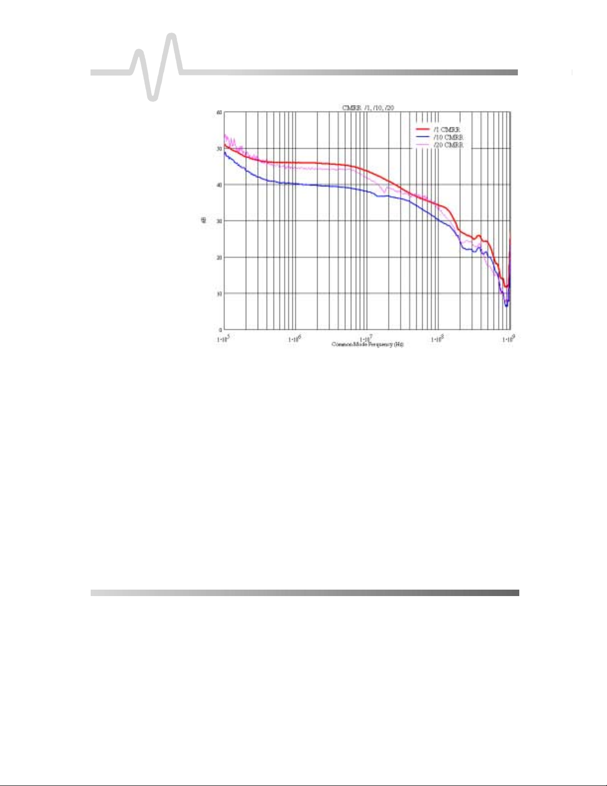
$3$FWLYH3UREH
Figure 13. Typical CMRR Graphs
² ISSUED: January 2000 AP034-OM-E Rev D
Page 5

GENERAL CHARACTERISTICS
Dimensions:
6SHFLILFDWLRQV
Temperature: 0 to 50 °C (operating)
–40 to 75 °C (storage)
Input Connectors: compatible with 0.025 in. (0.635 mm)
square pins
0.036 in. (0.91 mm) maximum
diameter (for round pins)
Power Requirements: powered from oscilloscope through
ProBus interface or with ADPPS
power supply
Control
Housing:
Head: Length: 4.0 in. (10.1 cm) w/o Attenuator or AC Coupler
Cable: Length: 42 in. (106 cm)
Weight: Probe only: 6.4 oz (0.18 kg)
Length: 3.625 in. (9.2 cm)
Width: 1.50 in. (3.8 cm)
Height: 1.00 in. (2.5 cm)
Width: 2.25 in. (2.25 cm)
Height: 0.625 in. (1.6 cm)
Diameter: 0.275 in. (7.0 mm)
Shipping: 2 lbs, 8.4 oz (1.15 kg)
AP034-OM-E Rev D ISSUED: January 2000 ²
Page 6

$3$FWLYH3UREH
COMPLIANCE AND CE RTIFICATIONS
EC Declaration of Conformity: Conforms to EMC Directive 89/335/EEC for electromagnetic
emission and immunity requirements.
EN 55011:1997: The probe has been tested to verify compliance with this
standard, Class B for Conducted and Radiated Emissions.
NE 50082-1:1997: The probe has been tested to verify compliance with this
standard for ESD, Radiated Immunity, EFT/Burst Immunity, Fast
Surge Immunity, Conducted Immunity, and Voltage Sags &
Interruptions. The line-related tests were performed with a model
ADPPS Probe Power Supply.
Conforms to Low Voltage Directive 73/23/EEC for product safety.
The probe has been designed to comply with EN 61010-1
Installation Category I, 42.4 V, Pollution Degree 1.
OPERATOR SAFETY
The probe is intended to be used only with instruments that are
connected to earth ground through the input BNC connector.
When you are using a ADPPS Power Supply Adapter, make sur e
that the adapter is connected to a BNC connector that is
grounded by the test instrument before connecting the probe
inputs to the test circuit.
Do not use in wet or explosive atmospheres. Remove any
contamination from the probe housing before connecting the
probe inputs to any circuit. Make sure that the surface of the
probe head is completely dry before connecting the inputs.
The use of the probe and/or the instrum ent it is connec ted to in a
manner other than specified may impair the protection
mechanisms.
Do not use the probe if any part is damaged. All maintenance
should be referred to qualified service personnel.
² ISSUED: January 2000 AP034-OM-E Rev D
Page 7

STANDARD ACCESSORIES
Hard Case
÷10 Plug-on Attenuator
÷20 Plug-on Attenuator
Plug-on AC Coupler
Probe Connection Accessory Kit:
Flex Lead Set (1)
Mini Clip, 0.8 mm (3)
Mini Clip, 0.5 mm (2)
Ground Lead (1)
Offset Pins, Round (4)
Square Pin Header Strip (1)
Manual, AP034 Active Differential Probe Instruction
OPTIONAL A CCESSORIES
ADPPS Power Supply
OSCILLOSCOPE SOFTWARE COMPATIBILITY
6SHFLILFDWLRQV
For full control functionality of the probe, the LeCroy oscilloscope
must have software version 8.1.0 or higher loaded. T he software
version installed in a LeCroy oscilloscope can be verified by
pressing the S
HOW STATUS button on the front panel, then
selecting the System menu choice. T he probe can be us ed with
earlier versions of software; however, probe offset can only be
controlled through the buttons on the probe body. Also, the scale
factor will be displayed incorrectly in some modes.
If required, contact your local LeCroy representative for
information on upgrading the software in your oscilloscope.
# # #
AP034-OM-E Rev D ISSUED: January 2000 ²
Page 8

BLANK PAGE
$3$FWLYH3UREH
² ISSUED: January 2000 AP034-OM-E Rev D
 Loading...