

Page 1
|
|
g
g
I REMOTE CONTROL MANUAL
II
II
II
|
g
II
g
II
g
MODELS 9410/14/20/24/30/50
DUAL- AND QUAD-CHANNEL
DIGITAL OSCILLOSCOPES
I
li
g
a
Serial Number
May 1992
Page 2
g
I
i
n
ii
li
ii
li
LeCroy
Corporate Headquarters
700 Chestnut Ridge Road
Chestnut Ridge, NY 10977-6499
Tel: (914) 425-2000, TWX: 710-577-2832
European Headquarters
2, rue Pr~-de-la-Fontaine
P.O. Box 341
1217 Meyrin 1/Geneva, Switzerland
Tel.: (022) 719 21 11, Telex: 419 058
Copyright~ May 1992, LeCroy. All rights reserved, information in this
publication supersedes all earlier versions. Specifications subject to change.
il
i
ii
g
li
i
II
g
II
L
Page 3
1
1
I TABLE OF CONTENTS
General Information
Initial Inspection
Warranty
Product Assistance
Maintenance Agreements
Document Discrepancies
Service Procedure
Return Procedure
2 About Remote Control
GPIB Implementation Standard
Program Messages
Commands and Queries
Local and Remote State
Program Message Form
Command/Query Form
Response Message Form
3 GPIB Operation
GPIB Structure
Interface Capabilities
Addressing
GPIB Signals
IEEE 488.1 Standard Messages
Programming GPIB Transfers
Programming Service Requests
Instrument Polls
Driving a Hard-copy Device
1
1
1
1
2
2
2
11
11
12
12
13
15
19
21
25
4 RS-232-C Operation
Introduction
RS-232-C Pin Assignments
RS-232-C Configuration
Commands Simulating GPIB Commands
29
29
30
33
Page 4

II
Table of Contents
System Commands
Organization
Command Summary
Command Execution
Command Notation
6
Waveform Structure
Introduction
Logical Data Blocks of a Waveform
Inspect? Command
Waveform? Command
Waveform Command
More Control of Waveform Queries
High-speed Waveform Transfer
Status Registers
Overview of Status and Service Request Reporting
Status Byte Register (STB)
Standard Event Status Register (ESR)
Standard Event Status Enable Register (ESE)
Service Request Enable Register (SRE)
Parallel Poll Enable Register (PRE)
Internal State Change Status Register (INR)
Internal State Change Enable Register (INE)
Command Error Status Register (CMR)
Device Dependent Error Status Register (DDR)
Execution Error Status Register (EXR)
User Request Status Register (URR)
35
35
37
37
179
179
180
182
187
188
188
191
193
194
195
195
195
195
196
196
196
196
196
|
|
|
Page 5
Appendix A
Table of Contents
Example 1: Use of the Interactive
GPIB Program ’IBIC’
Example 2: GPIB Program for IBM PC
(High-level Function Calls)
Example 3: GPIB Program for IBM PC
(Low-level Function Calls)
Appendix B
The Waveform Template
199
200
202
205
Page 6

Page 7
1
GENERAL INFORMATION
INITIAL INSPECTION
WARRANTY
It is recommended that the shipment be thoroughly inspected immediately upon delivery to the purchaser. All material in the
container should be checked against the enclosed Packing List.
LeCroy cannot accept responsibility for shortages in comparison
with the Packing List unless notified promptly. If the shipment is
damaged in any way, please contact the Customer Service Depart-
ment or local field office immediately.
LeCroy warrants its oscilloscope products to operate within specifications under normal use for a period of two years from the date of
shipment. Spares, replacement parts and repairs are warranted for
90 days. The instrument’s firmware is thoroughly tested and
thought to be functional, but is supplied "as is" with no warranty of
any kind covering detailed performance. Products not manufac-
tured by LeCroy are covered solely by the warranty of the original
equipment manufacturer.
In exercising this warranty, LeCroy will repair or, at its option,
replace any product returned to the Customer Service Department
or an authorized service facility within the warranty period, provided that the warrantor’s examination discloses that the product
is defective due to workmanship or materials and that the defect
has not been caused by misuse, neglect, accident or abnormal conditions or operation.
The purchaser is responsible for transportation and insurance
charges for the return of products to the servicing facility. LeCroy
will return all in-warranty products with transportation prepaid.
This warranty is in lieu of all other warranties, expressed or implied, including but not limited to any implied warranty of
merchantability, fitness, or adequacy for any particular purpose or
use. LeCroy shall not be liable for any special, incidental, or con-
sequential damages, whether in contract or otherwise.
PRODUCT ASSISTANCE
MAINTENANCE
AGREEMENTS
Answers to questions concerning installation, calibration, and use
of LeCroy equipment are available from the Customer Service
Department, 700 Chestnut Ridge Road, Chestnut Ridge, New
York 10977-6499, U.S.A., tel. (914)578-6061, and 2, rue
Pr6-de-la-Fontaine, 1217 Meyrin 1, Geneva, Switzerland, tel.
(41)22/719 21 11, or your local field engineering office.
LeCroy offers a selection of customer support services. Maintenance agreements provide extended warranty and allow the
customer to budget maintenance costs after the initial two year
warranty has expired. Other services such as installation, training,
enhancements and on-site repair are available through specific
Supplemental Support Agreements.
Page 8
General Information
DOCUMENTATION
DISCREPANCIES
SERVICE PROCEDURE
RETURN PROCEDURE
LeCroy is committed to providing state-of-the-art instrumenta-
tion and is continually refining and improving the performance of
its products. While physical modifications can be implemented
quite rapidly, the corrected documentation frequently requires
more time to produce. Consequently, this manual may not agree in
every detail with the accompanying product. There may be small
discrepancies in the values of components for the purposes of
pulse shape, timing, offset, etc., and, occasionally, minor logic
changes. Where any such inconsistencies exist, please be assured
that the unit is correct and incorporates the most up-to-date cir-
cuitry. In a similar way the firmware may undergo revision when
the instrument is serviced. Should this be the case, manual up-
dates will be made available as necessary.
Products requiring maintenance should be returned to the Cus-
tomer Service Department or authorized service facility. LeCroy
will repair or replace any product under warranty at no charge.
The purchaser is only responsible for transportation charges.
For all LeCroy products in need of repair after the warranty period, the customer must provide a Purchase Order Number before
repairs can be initiated. The customer will be billed for parts and
labor for the repair, as well as for shipping.
To determine your nearest authorized service facility, contact the
Customer Service Department or your field office. All products
returned for repair should be identified by the model and serial
numbers and include a description of the defect or failure, name
and phone number of the user, and, in the case of products returned to the factory, a Return Authorization Number (RAN).
The RAN may be obtained by contacting the Customer Service
Department in New York, tel. (914)578-6061, in Geneva, tel.
(41)22/719 21 11, or your nearest sales office.
Return shipments should be made prepaid. LeCroy will not accept
C.O.D. or Collect Return Shipments. Air-freight is generally recommended. Wherever possible, the original shipping carton
should be used. If a substitute carton is used, it should be rigid and
be packed such that the product is surrounded with a minimum of
four inches of excelsior or similar shock-absorbing material. In
addressing the shipment, it is important that the Return Authoriza-
tion Number be displayed on the outside of the container to ensure
its prompt routing to the proper department within LeCroy.
Page 9
2
ABOUT REMOTE CONTROL
Two modes of operation are available in the oscilloscope. The in-
strument may be operated either manually, by using the
front-panel controls, or remotely by means of an external control-
ler (which is usually a computer, but may be a simple terminal).
This Remote Control Manual describes how to control the oscillo-
scope in the remote mode. For explanations on how to manually
set front-panel controls, refer to the Operator’s Manual.
The oscilloscope is remotely controlled via either the GPIB (Gen-
eral Purpose Interface Bus) or the RS-232-C communication
ports. Whenever the rear-panel GPIB address switches are set be-
tween 0 and 30, control is via GPIB; when they are at 31 or above,
control is via RS-232-C. The instrument can be fully controlled in
remote mode. The only actions which cannot be performed re-
motely are switching on the instrument or setting the remote
address.
This section introduces the basic remote control concepts which
are common to both RS-232-C and GPIB. It also presents a brief
description of remote control messages.
Sections 3 and 4 explain how to send program messages over the
GPIB or the RS-232-C interfaces, respectively. Section 5 alphabetically lists all the remote control commands. Section 6 is a
detailed description and tutorial of the transfer and format of
waveforms, whereas Section 7 explains the use of status bytes for
error reporting. Appendix A shows some complete programming
examples. Appendix B contains a printout of a waveform tem-
plate.
GPIB IMPLEMENTATION
STANDARD
PROGRAM MESSAGES
1. ANSI/IEEE Std. 488.2-1987, "IEEE Standard Codes, Formats, Protocols, and Common Commands", The
Institute of Electrical and Electronics Engineers Inc., 345 East 47th Street, New York, NY 10017, USA.
The remote commands conform to the GPIB IEEE 488.2 stan-
1.
dard
IEEE 488.1 standard which dealt mainly with electrical and me-
chanical issues. The IEEE 488.2 recommendations have also
been adopted for RS-232-C communications whenever applica-
ble.
To remotely control the oscilloscope the controller must send pro-
gram messages which conform to precise format structures. The
instrument will execute all program messages which are in the cor-
rect form and ignore those where errors are detected.
This standard may be seen as an extension of the
Page 10
About Remote Control
Warning or error messages are normally not reported by the instrument, unless the controller explicitly examines the relevant status
register, or if the status enable registers have been set in such a way
that the controller can be interrupted when an error occurs. The
status registers are explained in Section 7.
During the development of the control program it is possible to
observe all remote control transactions, including error messages,
on an external monitor connected to the RS-232-C port. Refer to
the command "COMM_HELP" for further details.
COMMANDS
AND QUERIES
Program messages consist of one or several commands or queries.
A command directs the instrument to change its state, e.g. to
change its time base or vertical sensitivity. A query asks the instrument about its state. Very often, the same mnemonic is used for a
command and a query, the query being identified by a <?> after
the last character.
For example, to change the time base to 2 msec/div, the controller
should send the following command to the instrument
TIME DIV 2 MS
To ask the instrument about its time base, this query should be
sent
TIME DIV?
A query causes the instrument to send a response message. The
control program should read this message with a "read" instruc-
tion to the GPIB or RS-232-C interface of the controller. The
response message to the query above might be
TIME DIV 10 NS
m
The portion of the query preceding the question mark is repeated
as part of the response message. If desired, this text may be suppressed with the command "COMM_HEADER".
Depending on the state of the instrument and the computation to
be done, the controller may have to wait up to several seconds for
a response. Command interpretation does not have priority over
other oscilloscope activities. It is therefore judicious to set the controller IO timeout conditions to 3 or more seconds. In addition, it
must be remembered that an incorrect query message will not generate a response message.
4
Page 11
About Remote Control 2
LOCAL AND REMOTE
STATE
PROGRAM MESSAGE
FORM
As a rule, remote commands are only executed by the instrument
when it is in the REMOTE state, whereas queries are always executed. A few commands which don’t affect the state of the front
panel are also executed in LOCAL (refer to the beginning of Section 5 for a list of these commands). When the instrument is in
REMOTE, all front-panel controls are disabled, except the lefthand menu buttons, the intensity controls (which can be disabled
with the command "INTENSITY") and the LOCAL button
(which can be disabled by setting the instrument to LOCAL
LOCKOUT). For an explanation on how to set the instrument to
LOCAL, REMOTE or LOCAL LOCKOUT, refer to Section 3 for
GPIB and to Section 4 for RS-232-C.
An instrument is remotely controlled with program messages
which consist of one or several commands or queries, separated by
semicolons <;> and ended by a terminator:
<command/query>; .........
Upper and/or lower case characters can be used for program messages.
The instrument does not decode an incoming program message
before a terminator has been received (exception: if the program
message is longer than the 256 byte input buffer of the instrument,
the oscilloscope starts analyzing the message when the buffer is
full). The commands or queries are executed in the order in which
they are transmitted.
In GPIB mode, the following are valid terminators:
<NL> New-line character (i.e. the ASCII new-line
character, whose decimal value is 10).
<NL> <EOI> New-line character with a simultaneous <EOI>
signal.
<EOI> <EOI> signal together with the last character of
the program message.
Note: The <EOI> signal is a dedicated GPIB interface line which
can be set with a special call to the GPIB interface driver. Refer to
the GPIB interface manufacturer’s manual and support programs.
The <NL> <EOI> terminator is always used in response messages
sent by the instrument to the controller.
In RS-232-C, the terminator may be defined by the user with the
command "COMM_RS232". The default value is <CR>, i.e. the
ASCII carriage return character, the decimal value of which is 13.
;<command/query> <terminator>
Page 12
About Remote Control
|
|
Examples
COMMAND/QUERY
FORM
Example
GRID DUAL This program message consists of a
single command which instructs the
instrument to display a dual grid.
The terminator is not shown since it
is usually automatically added by
the interface driver routine which
writes to the GPIB (or RS-232).
BWL ON; DISPLAY OFF; DATE?
This program message consists of
two commands, followed by a
query. They instruct the instrument
to turn on the bandwidth limit, turn
off the display, and then ask for the
current date. Again, the terminator
is not shown.
The general form of a command or a query consists of a command
header <header> which is optionally followed by one or several
parameters <data> separated by commas:
<header>[?] <data> .....
The notation [?] shows that the question mark is optional (turning
the command into a query). The detailed listing of all commands
in Section 5 indicates which commands may also be queries.
There is a space between the header and the first parameter.
There are commas between parameters.
DATE 15,OCT,1989,13,21,16
<data>
This command instructs the oscillo-
scope to set its date and time to 15
OCT 1989, 13:21:16. The command header "DATE" indicates
the action, the 6 data values specify
it in detail.
|
|
|
|
I
1
I
|
|
|
1
Header
6
The header is the mnemonic form of the operation to be per-
formed by the oscilloscope. All command mnemonics are listed in
alphabetic order in Section 5.
The majority of the command/query headers have a long form for
optimum legibility and a short form for better transfer and decoding speed. The two forms are fully equivalent and can be used
interchangeably. For example, the following two commands for
switching to the automatic trigger mode are fully equivalent:
TRIG_MODE AUTO and TRMD AUTO
|
1
|
|
|
Page 13
About Remote Control 2
Some command/query mnemonics are imposed by the IEEE
488.2 standard. They are standardized so that different instruments present the same programming interface for similar
functions. All these mnemonics begin with an asterisk <*>, e.g.
the command "*RST" is the IEEE 488.2 imposed mnemonic for
resetting the instrument, whereas "*TST?" instructs the instrument to perform an internal self-test and to report the outcome.
Header path
Example
Some commands or queries apply to a sub-section of the oscilloscope, e.g. a single input channel or a trace on the display. In such
cases, the header must be preceded by a path name that indicates
the channel or trace to which the command applies. The header
path normally consists of a 2-letter path name followed by a colon
<:> which immediately precedes the command header.
Usually one of the waveform traces can be specified in the header
path (refer to the individual commands listed in Section 5 for details on which values apply to a given command header):
C1, C2
C3, C4
MC, MD
FE, FF Function E and F
EA, EB
EX, EX10 External trigger
CI:OFST -300 MV Set the offset of Channel 1 to
Header paths need only be specified once. Subsequent commands
whose header destination is not indicated are assumed to refer to
the last defined path. For example, the following commands are
identical:
C2:VDIV?; C2:OFST?
C2:VDIV?; OFST?
Channels 1 and 2
Channels 3 and 4 (in 4-channel instruments)
Memory C and D
Expand A and B
-300 mV
What is the vertical sensitivity and
the offset of channel 2?
Same as above, without repeating
the path.
Data
Whenever a command/query uses additional data values, they are
expressed in terms of ASCII characters. There is a single excep-
tion: the transfer of waveforms with the command/query
"WAVEFORM", where the waveform may be expressed as a sequence of binary data values. Refer to Section 6 for a detailed
explanation of the format of waveforms.
ASCII data can have the form of character, numeric, string or
block data.
Page 14

About Remote Control
|
|
Character data
Numeric Data
These are simple words or abbreviations for the indication of a
specific action.
BANDWIDTH LIMIT ON The data value "ON" indicates that
the bandwidth limit should be
turned on, rather than off.
In some commands, where as many as a dozen different parame-
ters can be specified, or where not all parameters apply at the same
time, the format requires pairs of data values. The first one names
the parameter to be modified and the second gives its value. Only
those parameter pairs to be changed need to be indicated.
HARDCOPY_SETUP DEV,HP7470A,PORT,GPIB,PSIZE,A4
Three pairs of parameters are specified. The first specifies the device
as the H7470A plotter (or compatible), the second indicates the
GPIB port and the third requests
the A4 format for paper size. While
the command "HARDCOPY SET-
UP" allows many more parameters,
they are either not relevant for plot-
ters or they are left unchanged.
The numeric data type is used to enter quantitative information.
Numbers can be entered as integers, as fractions or in exponential
representation.
EA:VPOS -5 Move the displayed trace of Expand A down-
wards by 5 divisions.
C2"OFST 3.56 Set the DC offset of Channel 2 to 3.56 V.
TDIV 5.0E-6 Adjust the time base to 5 issec/div.
Note: Numeric values may be followed by multipliers and units,
modifying the value of the numerical expression. The following
mnemonics are recognized:
|
|
|
|
|
|
|
|
|
II
|
II
II
II
|
|
Page 15
i
About Remote Control 2
I
EX
l
l
I
T 1E 12 Tera- G 1E9 Giga-
MA 1E6 Mega- K 1E3 kilo-
M
N 1E-9 nano- PI 1E-12
F 1E-15 femto- A 1E-18 atto-
For example, there are many ways of setting the time base of the
instrument to 5 ~tsec/div:
TDIV 5E-6
1E18
1E-3 milli- U 1E-6 micro-
I
TDIV 5 US
l
TDIV 5000 NS
TDIV 5000E-3 US
String Data
This data type enables the transfer of a (long) string of characters
as a single parameter. String data are formed by simply enclosing
any sequence of ASCII characters between simple or double
quotes.
MESSAGE ’Connect probe to point J3’
The instrument displays this message in the Message field above
the grid.
Exa-
PE
Exponential notation, without any
suffix.
Suffix multiplier "U" for 1E-6,
with the (optional) suffix "S" for
seconds.
1E15
Peta-
pico-
Block Data
RESPONSE MESSAGE
FORM
These are binary data values coded in hexadecimal ASCII, i.e.
4-bit nibbles are translated into the digits 0,...9, A .... F and trans-
mitted as ASCII characters. They are only used for the transfer of
waveforms (command "WAVEFORM") and of the instrument
configuration (command "PANEL_SETUP")
The instrument sends a response message to the controller, as an
answer to a query. The format of such messages is the same as that
of program messages, i.e. individual responses in the format of
commands, separated by semicolons <;> and ended by a terminator. They can be sent back to the instrument in the form in which
they are received, and will be accepted as valid commands. In
GPIB response messages, the <NL> <EOI> terminator is always
used.
For example, if the controller sends the program message:
TIME_DIV? ;TRIG_MODE NORM;C 1 :COUPLING? (terminator
not shown)
Page 16
About Remote Control
|
|
the instrument might respond as follows:
TIME_DIV 50 NS;C 1:COUPLING D50 (terminator not shown)
The response message only refers to the queries, i.e.
"TRIG_MODE" is left out. If this response is sent back to the
instrument, it is a valid program message for setting its time base to
50 nsec/div and the input coupling of Channel 1 to 50 ~.
Whenever a response is expected from the instrument, the control
program must instruct the GPIB or RS-232-C interface to read
from the instrument. If the controller sends another program message without reading the response to the previous one, the
response message in the output buffer of the instrument is discarded.
The instrument uses somewhat stricter rules for response messages
than for the acceptance of program messages, Whereas the con-
troller may send program messages in upper or lower case
characters, response messages are always returned in upper case.
Program messages may contain extraneous spaces or tabs (white
space), response messages do not. Whereas program messages
may contain a mixture of short and long command/query headers,
response messages always use short headers as a default. However,
the instrument can be forced with the command
"COMM_HEADER" to use long headers or no headers at all. If
the response header is omitted, the response transfer time is mini-
mized, but such a response could not be sent back to the
instrument again. In this case suffix units are also suppressed in the
response.
If the trigger slope of Channel 1 is set to negative, the query
"CI:TRSL?" could yield the following responses:
CI:TRIG_SLOPE NEG
CI:TRSL NEG
NEG
Waveforms which are obtained from the instrument using the
query "WAVEFORM?" constitute a special kind of response mes-
sage. Their exact format can be controlled with the commands
"COMM FORMAT" and "COMM ORDER", as explained in
Section ~
header format: long
header format: short
header format: off
|
|
|
|
|
|
|
|
|
|
|
|
|
10
|
|
|
Page 17
|
GPIB OPERATION
I
3
|
This section describes how to remotely control the oscilloscope via
the GPIB. Topics discussed include interface capabilities, addressing, standard bus commands, and polling schemes.
GPIB STRUCTURE
INTERFACE
CAPABILITIES The interface capabilities of the oscilloscope include the following
The GPIB is like an ordinary computer bus, except that it interconnects independent devices via a cable bus whereas a computer
has its circuit cards interconnected via a backplane bus. The GPIB
carries program messages and interface messages:
¯ Program messages, often called device-dependent messages,
contain programming instructions, measurement results, instrument status and waveform data. Their general form is
described in Section 2.
¯
Interface messages manage the bus itself. They perform functions such as initializing the bus, addressing and unaddressing
devices and setting remote and local modes.
Devices on the GPIB can be listeners, talkers, and/or controllers.
A talker sends program messages to one or more listeners. A controller manages the flow of information on the bus by sending
interface messages to the devices.
The oscilloscope can be a talker or a listener, but not a controller.
The host computer, however, must be able to act as a listener,
talker and controller. For details on how the controller configures
the GPIB for specific functions, refer to the GPIB interface manufacturer’s manual.
IEEE 488.1 definitions:
AH1
SH1
L4
T5
SR1
RL1
DC1
DT1
PP1
CO
E2
Complete Acceptor Handshake
Complete Source Handshake
Partial Listener Function
Complete Talker Function
Complete Service Request Function
Complete Remote/Local Function
Complete Device Clear Function
Complete Device Trigger
Parallel Polling: remote configurability
No Controller Functions
Tri-state Drivers
11
Page 18
GPIB Operation
|
|
ADDRESSING
GPIB SIGNALS
Every device on the GPIB has an address. When the thumbwheel
address switches on the rear panel of the oscilloscope are set to a
value between 0 and 30, the instrument can be controlled via
GPIB. When the switches are set to above 30, the instrument can
execute talk-only operations on the GPIB, for example driving a
GPIB plotter. In this case no controller is present and the instrument is directly connected to the plotter. Addresses above 30 also
enable the instrument to be controlled via the RS-232-C port.
The instrument reads the address switches once at power on, or
when the RESET button on the rear panel is pressed. If the address is changed during operation, the instrument must be
powered again to enable the new address. The value of the GPIB
address appears in the menu "Auxiliary Setups".
If the oscilloscope is addressed to talk, it will remain configured to
talk until a universal untalk command (UNT), its own listen ad-
dress (MLA), or another instrument’s talk address is received.
Similarly, if the oscilloscope is addressed to listen, it will remain
configured to listen until a universal unlisten command (UNL),
its own talker address (MTA) is received.
The bus system consists of 16 signal lines and 8 ground or shield
lines. The signal lines are divided into 3 groups:
¯
8 data lines
¯
3 handshake lines
¯
5 interface management lines
II
n
i
l
l
l
II
II
Data Lines
Handshake Lines
Interface Management Lines
12
The eight data lines, usually called DI01 through DI08, carry both
program and interface messages. Most of the messages use the
7-bit ASCII code, in which case DI08 is unused.
These three lines control the transfer of message bytes between
devices. The process is called a three-wire interlocked handshake
and it guarantees that the message bytes on the data lines are sent
and received without transmission error.
The following five lines manage the flow of information across the
interface.
ATN (ATteNtion): The controller drives the ATN line true when
it uses the data lines to send interface messages such as talk and
listen addresses or a device clear (DCL) message. When ATN
false, the bus is in the data mode for the transfer of program messages from talkers to listeners.
IFC (InterFace Clear): The controller sets the IFC line true
initialize the bus.
II
II
II
n
II
g
g
II
Page 19
n
|
|
GPIB Operation 3
REN (Remote ENable): The controller uses this line to place devices in remote or local program mode.
SRQ (Service ReQuest): Any device can drive the SRQ line true
to asynchronously request service from the controller. This is the
equivalent of a single interrupt line on a computer bus.
EOI (End Or Identify): This line has two purposes. The talker
uses it to mark the end of a message string. The controller uses it to
tell devices to identify their response in a parallel poll (discussed
later in this section).
I/O Buffers
IEEE 488.1
STANDARD MESSAGES
The instrument has a 256-byte input buffer and a 256-byte output
buffer. An incoming program message is not decoded before a
message terminator has been received. However, if the input buffer becomes full (because the program message is longer than the
buffer), the instrument starts analyzing the message. In this case
data transmission is temporarily halted, and the controller may
generate a timeout if the limit was set too low.
The IEEE 488.1 standard specifies not only the mechanical and
electrical aspects of the GPIB, but also the low-level transfer pro-
tocol, e.g. it defines how a controller addresses devices, turns
them into talkers or listeners, resets them or puts them in the remote state. Such interface messages are executed with the
interface management lines of the GPIB, usually with ATN true.
All of these messages (except GET) are executed immediately
upon reception and not in chronological order with normal com-
mands.
Note: In addition to the IEEE 488.1 interface message standards,
the IEEE 488.2 standard specifies some standardized program
messages, i.e. command headers. They are identified with a leading asterisk <*> and are listed among the commands in Section 5.
The command list in Section 5 does not contain any command for
clearing the input/output buffers or for setting the instrument to
the remote state. This is because such commands are already spe-
cified as IEEE 488.1 standard messages. Refer to the GPIB
interface manual of the host controller as well as to its support
programs which should contain special calls for the execution of
these messages.
The following describes those IEEE 488.1 standard messages
which go beyond mere reconfiguration of the bus and which have
an effect on the operation of the instrument.
Device Clear
In response to a universal Device CLear (DCL) or a Selected Device Clear message (SDC), the oscilloscope clears the input/output
13
Page 20
GPIB Operation
buffers, aborts the interpretation of the current command (if any)
and clears any pending commands. Status registers and status en-
able registers are not cleared. Although DCL has an immediate
effect it can take several seconds to execute this command if the
instrument is busy.
I
I
I
I
Group Execute Trigger
Remote ENable
Local LOckout
Go To Local
The Group Execute Trigger message (GET) causes the oscillo-
scope to arm the trigger system. It is functionally identical to the
"*TRG" command.
This interface message is executed when the controller holds the
Remote ENable control line (REN) true and configures the instrument as a listener. The REMOTE LED on the front panel lights up
to indicate that the instrument is set to the remote mode. All the
front-panel controls are disabled except the left-hand menu but-
tons, the intensity controls and the LOCAL button. The menu
indications on the left-hand side of the screen no longer appear
since menus cannot now be operated manually. Whenever the
controller returns the REN line to false, all instruments on the bus
return to LOCAL. Individual instruments can be returned to LO-
CAL with the Go To Local message (see below).
As a rule, remote commands are only executed when the instru-
ment is in the remote state, whereas queries are always executed.
Local front-panel control may be regained by pressing the LO-
CAL push button, unless the instrument was placed in the Local
LOckout (LLO) mode.
The Local LOckout command (LLO) causes the LOCAL button
on the front panel of the oscilloscope to be disabled. The LLO
command can be sent in local or remote mode but only becomes
effective once the instrument has been set to the remote mode.
The Go To Local message (GTL) causes the instrument to return
to the local mode. All front-panel controls become active and the
menus on the left-hand side of the screen reappear. Thereafter,
whenever the instrument is addressed as a listener it will be imme-
diately set to the remote state again.
Note that a GTL message does not clear the local lockout if it was
set. Thus, whenever the instrument returns to the remote state the
local lockout mode would immediately be effective again.
A command string should not be immediately followed by a GTL
message. Since GTL is executed at once, the instrument may already be returned to the local state before the commands in the
input buffer are interpreted. Therefore, the instrument may refuse
to execute them if they require the instrument to be in REMOTE.
I
I
I
I
I
I
I
I
I
I
I
I
14
I
I
Page 21
GPIB Operation 3
A safe way to ensure that all commands have been interpreted is to
append a query (e.g. "*STB?") to the command string and to wait
for the response before sending a GTL.
InterFace Clear
PROGRAMMING
GPIB TRANSFERS
Configuring the
GPIB Hardware
The InterFace Clear message (IFC) initializes the GPIB but has
effect on the operation of the oscilloscope.
To illustrate the GPIB programming concepts a number of examples written in BASICA are included in this section. It is assumed
that the controller is IBM-PC compatible, running under DOS,
and that it is equipped with a National Instruments2 GPIB inter-
face card. GPIB programming with other languages such as C or
Pascal is quite similar.
If you use another computer or another GPIB interface, refer to
the interface manual for installation procedures and subroutine
calls similar to those described here.
Check that the GPIB interface is properly installed in the comput-
er. If it is not, follow the installation instructions of the interface
manufacturer. In the case of the National Instruments interface, it
is possible to modify the base I/O address of the board, the DMA
channel number and the interrupt line setting using switches and
jumpers. In our program examples, they are assumed to be left in
their default positions.
Connect the oscilloscope to the computer with a GPIB interface
cable. Set the GPIB address on the rear of the instrument to the
required value. The program examples assume that it is set to 4.
Remember to power the instrument up after setting the GPIB ad-
dress.
Configuring the
GPIB Driver Software
National Instruments Corporation,
2.
The host computer needs an interface driver which handles the
transactions between the user’s programs and the interface board.
In the case of the National Instruments interface, the installation
procedure:
¯ copies the GPIB handler GPIB.COM into the boot directory.
¯ modifies the DOS system configuration file CONFIG.SYS to
declare the presence of the GPIB handler.
¯ creates a sub-directory GPIB-PC.
¯ installs in GPIB-PC a number of files and programs which are
useful for testing and reconfiguring the system, and for writing
user programs.
12109 Technology Boulevard, Austin, Texas 78727
15
Page 22
GPIB Operation
The following files in the sub-directory GPIB-PC are of particular
use:
IBIC. EXE allows interactive control of the GPIB via functions en-
tered at the keyboard. Use of this program is highly recommended
to anyone who is not familiar with GPIB programming or with the
oscilloscope’s remote commands. An example of the use of
IBIC.EXE is shown in Appendix A.
DECL.BAS is a declaration file that contains code to be included
at the beginning of any BASICA application program. Simple
application programs can be quickly written by appending the
user’s instructions to DECL.BAS and executing the complete file.
IBCONF.EXE is an interactive program which allows inspection
or modification of the current settings of the GPIB handler. To run
IBCONF.EXE, refer to the National Instruments user’s manual.
In the program examples in this section, it is assumed that the
National Instruments GPIB driver GPIB.COM is in its default
state, i.e. that the user has not modified it with IBCONF.EXE.
This means that the interface board can be referred to by the symbolic name ’GPIB0’ and that devices on the GPlB bus with
addresses between 1 and 16 can be called by the symbolic names
’DEVI’ to ’DEV16’.
Note: If you have a National Instruments PC2 interface card rather than PC2A, you must run IBCONF to declare the presence of
this card rather than the default PC2A.
|
|
l
|
II
I
l
II
II
II
Simple Transfers
16
For a large number of remote control operations it is sufficient to
use just 3 different subroutines (IBFIND, IBRD and IBWRT) pro-
vided by National Instruments. The following complete program
reads the time-base setting of the oscilloscope and displays it on
the terminal:
1-99
100
110
120
130
140
150
160
<DECL.BAS>
DEV$="DEV4"
CALL IBFIND(DEV$,SCOPE%)
CMD$="TDIV?"
CALL IBWRT(SCOPE%,CMD$)
CALL IBRD(SCOPE%,RD$)
PRINT RD$
END
II
II
II
II
II
II
II
II
Page 23
GPIB Operation 3
Explanation
Lines 1 - 99 are a copy of the file DECL.BAS supplied by National
Instruments. The first 6 lines are required for the initialization of
the GPIB handler. The other lines are declarations which may be
useful for larger programs, but are not really required code. The
sample program above only uses the strings CMD$ and RD$ which
are declared in DECL.BAS as arrays of 255 characters.
Note: DECL.BAS requires access to the file BIB.M during the
GPIB initialization. BIB.M is one of the files supplied by National
Instruments, and it must exist in the directory currently in use.
Note: The first 2 lines of DECL.BAS each contain a string
"XXXXX" which must be replaced by the number of bytes which
determine the maximum workspace for BASICA (computed by
subtracting the size of BIB.M from the space currently available in
BASICA). For example, if the size of BIB.M is 1200 bytes and
when BASICA is loaded it reports "60200 bytes free ", you should
replace "XXXXX" by the value 59000 or less.
Lines 100 and 110 open the device "DEV4" and associate with it
the descriptor "SCOPE%". All I/O calls from now on will refer to
"SCOPE%". The default configuration of the GPIB handler recog-
"DEV4"
nizes
If you want to use another GPIB address between 1 and 16, use
the string "DEVx" with x = 1...16. If you want to use another
name, run IBCONF.EXE to declare this name to the handler.
Lines 120 and 130 prepare the command string TDIV? and trans-
fer it to the instrument. The command instructs it to respond with
the current setting of the time base.
Line 140 reads the response of the instrument and places it into
the character string RD$.
Line 150 displays the response on the terminal.
When running this sample program, the oscilloscope will automati-
cally be set to the remote state when IBWRT is executed, and will
remain in that state. Pressing the LOCAL button on the front pan-
el will return the oscilloscope to local mode if the GPIB handler
was modified to inhibit Local LOckout (LLO).
Here is a slightly modified version of the sample program which
checks if any error occurred during GPIB operation:
and associates with it a device with GPIB address 4.
17
Page 24
GPIB Operation
|
|
Some Additional
Driver Calls
1-99
100
110
120
130
140
150
160
170
180
190
200
210
25O
260
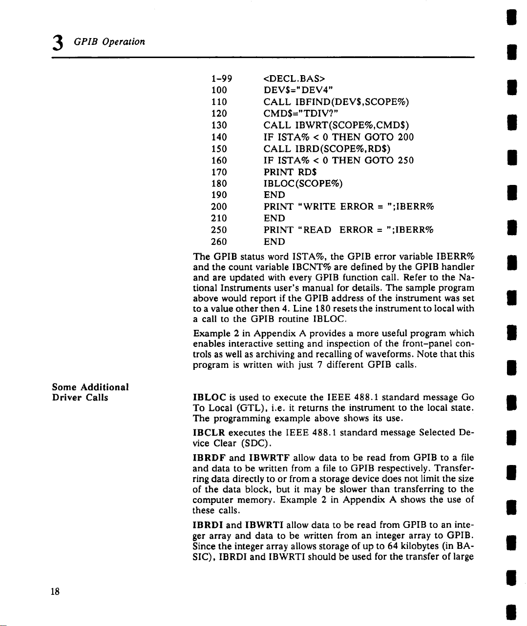
The GPIB status word ISTA%, the GPIB error variable IBERR%
and the count variable IBCNT% are defined by the GPIB handler
and are updated with every GPIB function call. Refer to the Na-
tional Instruments user’s manual for details. The sample program
above would report if the GPIB address of the instrument was set
to a value other then 4. Line 180 resets the instrument to local with
a call to the GPIB routine IBLOC.
Example 2 in Appendix A provides a more useful program which
enables interactive setting and inspection of the front-panel controis as well as archiving and recalling of waveforms. Note that this
program is written with just 7 different GPIB calls.
IBLOC is used to execute the IEEE 488.1 standard message Go
To Local (GTL), i.e. it returns the instrument to the local state.
The programming example above shows its use.
IBCLR executes the IEEE 488.1 standard message Selected De-
vice Clear (SDC).
IBRDF and IBWRTF allow data to be read from GPIB to a file
and data to be written from a file to GPIB respectively. Transferring data directly to or from a storage device does not limit the size
of the data block, but it may be slower than transferring to the
computer memory. Example 2 in Appendix A shows the use of
these calls.
IBRDI and IBWRTI allow data to be read from GPIB to an integer array and data to be written from an integer array to GPIB.
Since the integer array allows storage of up to 64 kilobytes (in BA-
SIC), IBRDI and IBWRTI should be used for the transfer of large
<DECL.BAS>
DEV$=" DEV4"
CALL IBFIND(DEV$,SCOPE%)
CMD$="TDIV?"
CALL IBWRT(SCOPE%,CMD$)
IF ISTA% < 0 THEN GOTO 200
CALL IBRD(SCOPE%,RD$)
IF ISTA% < 0 THEN GOTO 250
PRINT RD$
IBLOC(SCOPE%)
END
PRINT "WRITE ERROR = ";IBERR%
END
PRINT "READ ERROR = ";IBERR%
END
I
II
l
I
il
II
n
l
ii
m
ii
il
II
n
18
ti
II
Page 25
PROGRAMMING
SERVICE REQUESTS
GPIB Operation 3
data blocks to the computer memory, rather than IBRD or IBWRT
which are limited to 256 bytes by the BASIC string length. Note
that IBRDI and IBWRTI only exist for BASIC, since the function
calls IBRD and IBWRT for more modem programming languages,
such as C, are much less limited in the data block size.
IBTMO can be used to change the time-out value during program
execution. The default value of the GPIB driver is 10 seconds, e.g.
if the instrument does not respond to a IBRD call, IBRD will return
with an error after the specified time.
IBTRG executes the IEEE 488.1 standard message Group Execute Trigger (GET), which causes the oscilloscope to arm the
trigger system.
National Instruments supply a number of additional function calls.
In particular, it is possible to use the so-called board level calls
which allow a very detailed control of the GPIB. The use of such
calls is shown in Example 3 of Appendix A.
When an oscilloscope is used in a remote application, events often
occur asynchronously, i.e. at times that are unpredictable for the
host computer. The most common case is waiting for a trigger after
the instrument has been armed. The controller must wait until the
acquisition is finished before it can read the acquired waveform.
The simplest way of checking if a certain event has occurred is by
continuously or periodically reading the status bit associated with it
until the required transition is detected. Continuous status bit poll-
ing is described in more detail in the sub-section "Instrument
Polls". For a complete explanation of the status bytes refer to Section 7.
A potentially more efficient way of detecting events occurring in
the instrument is the use of the Service Request (SRQ). This GPIB
interrupt line can be used to interrupt program execution in the
controller. Therefore, the controller can execute other programs
while waiting for the instrument. Unfortunately, not all interface
manufacturers support the programming of interrupt service routines. In particular, National Instruments only supports the SRQ
bit within the ISTA% status word. This requires the user to continuously or periodically check this word, either explicitly or with the
function call IBWAIT. In the absence of real interrupt service routines the use of SRQ may not be very advantageous.
In the default state, after power-on, the Service ReQuest is disabled. The SRQ is enabled by setting the Service Request Enable
register with the command "*SRE" and specifying which event
should generate an SRQ. The oscilloscope will interrupt the con-
19
Page 26
GPIB Operation
3
troller as soon as the selected event(s) occur by asserting the SRQ
interface line. If several devices are connected to the GPIB, the
controller may have to identify which instrument caused the inter-
rupt by serial polling the various devices.
Note: The SRQ bit is latched until the controller reads the STatus
Byte Register (STB). The action of reading the STB with the com-
mand "*STB?" clears the register contents except the MAV bit
(bit 4) until a new event occurs. Service requesting may be dis-
abled by clearing the SRE register ("*SRE 0").
|
|
II
II
l
Example 1
Example 2
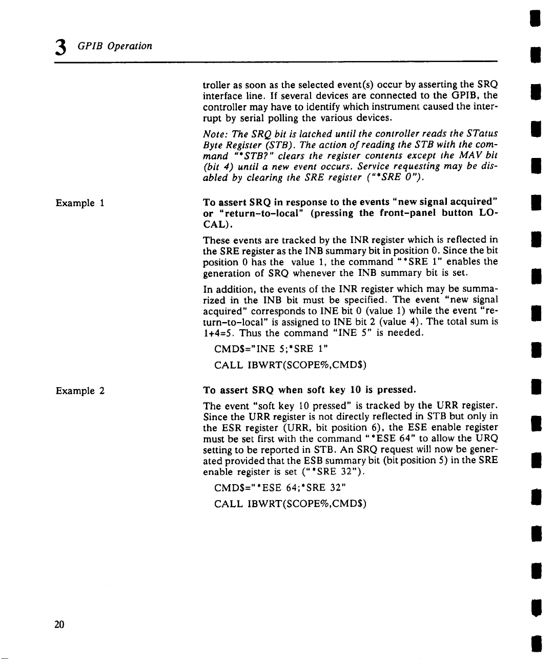
To assert SRQ in response to the events "new signal acquired"
or "return-to-local" (pressing the front-panel button LO-
CAL).
These events are tracked by the INR register which is reflected in
the SRE register as the INB summary bit in position 0. Since the bit
position 0 has the value 1, the command "*SRE 1" enables the
generation of SRQ whenever the INB summary bit is set.
In addition, the events of the INR register which may be summa-
rized in the INB bit must be specified. The event "new signal
acquired" corresponds to INE bit 0 (value 1) while the event "re-
turn-to-local" is assigned to INE bit 2 (value 4). The total sum
1+4=5. Thus the command "INE 5" is needed.
CMD$="INE 5;*SRE 1"
CALL IBWRT(SCOPE%,CMD$)
To assert SRQ when soft key 10 is pressed.
The event "soft key 10 pressed" is tracked by the URR register.
Since the URR register is not directly reflected in STB but only in
the ESR register (URR, bit position 6), the ESE enable register
must be set first with the command "*ESE 64" to allow the URQ
setting to be reported in STB. An SRQ request will now be gener-
ated provided that the ESB summary bit (bit position 5) in the SRE
enable register is set ("*SRE 32").
CMD$="*ESE 64;*SRE 32"
CALL IBWRT(SCOPE%,CMD$)
l
I
I
II
l
l
I!
n
II
2O
II
II
II
II
Page 27
GPIB Operation 3
INSTRUMENT POLLS
Continuous Poll
State transitions occurring within the instrument can be remotely
monitored by polling selected internal status registers. This subsection discusses a number of polling methods which may be used
to detect the occurrence of a given event.
1. Continuous poll
2. Serial poll
Parallel poll
3.
4. *IST poll
To emphasize the differences between these methods, the same
example will be presented in each case, i.e. determining if a new
acquisition has taken place. By far the simplest poll is the continuous poll. The other methods only make sense if interrupt service
routines (servicing the SRQ line) are supported or if multiple devices on GPIB must be monitored simultaneously.
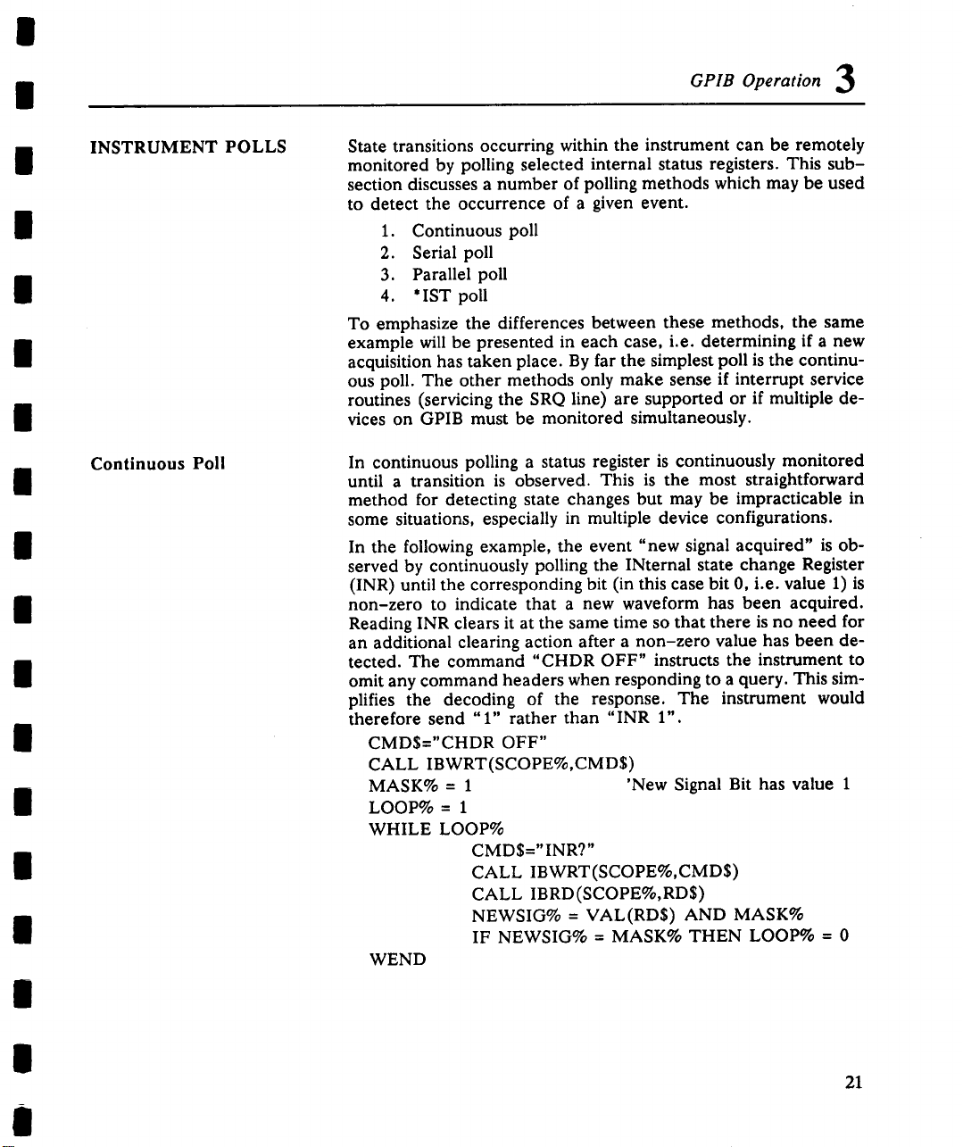
In continuous polling a status register is continuously monitored
until a transition is observed. This is the most straightforward
method for detecting state changes but may be impracticable in
some situations, especially in multiple device configurations.
In the following example, the event "new signal acquired" is ob-
served by continuously polling the INternal state change Register
(INR) until the corresponding bit (in this case bit 0, i.e. value 1)
non-zero to indicate that a new waveform has been acquired.
Reading INR clears it at the same time so that there is no need for
an additional clearing action after a non-zero value has been detected. The command "CHDR OFF" instructs the instrument to
omit any command headers when responding to a query. This simplifies the decoding of the response. The instrument would
therefore send "1" rather than "INR 1".
CMD$="CHDR OFF"
CALL IBWRT(SCOPE%,CMD$)
MASK% = 1
LOOP% = 1
WHILE LOOP%
CMD$="INR?"
CALL IBWRT(SCOPE%,CMD$)
CALL IBRD(SCOPE%,RD$)
NEWSIG% = VAL(RD$) AND MASK%
IF NEWSIG% = MASK% THEN LOOP% = 0
WEND
’New Signal Bit has value 1
21
Page 28
GPIB Operation
3
|
|
Serial Poll
Serial polling takes place once the SRQ interrupt line has been
asserted. The controller examines which instrument has generated
the interrupt by inspecting the SRQ bit in the STB register of each
instrument. Because service request is based on an interrupt mech-
anism, serial polling offers a reasonable compromise in terms of
servicing speed in multiple device configurations.
In the following example, the command "INE 1" enables the
event "new signal acquired" to be reported in the INR to the INB
bit of the status byte STB. The command "*SRE 1" enables the
INB of the status byte to generate an SRQ whenever it is set. The
function call IBWAIT instructs the computer to wait until one of
three conditions occur: &Hg000 in the mask (MASK%) corresponds to a GPIB error, &H4000 to a time-out error and &H0800
to the detection of RQS (ReQuest for Service generated by the
SRQ bit).
Whenever IBWAIT detects RQS it automatically performs a serial
poll to find out which instrument generated the interrupt. It will
only exit if there was a time-out or if the instrument "SCOPE%"
generated SRQ. The additional function call IBRSP fetches the
value of the status byte which may be further interpreted. For this
example to function properly the value of ’Disable Auto Serial
Polling’ must be set ’off’ in the GPIB handler (use IBCONF.EXE
to check).
CMD$="*CLS; INE 1; *SRE 1"
CALL IBWRT(SCOPE%,CMD$)
MASK% = &HCg00
CALL IBWAIT(SCOPE%,MASK%)
IF (IBSTA% AND &HC000) <> 0 THEN PRINT "GPIB
Time-out Error" : STOP
CALL IBRSP(SCOPE%,SPR%)
PRINT "Status Byte = ", SPR%
Note: After the serial poll is completed, the RQS bit in the STB
status register is cleared. Note that the other STB register bits
remain set until they are cleared by means of a "* CLS" command
or the instrument is reset. If these bits are not cleared, they cannot
generate another interrupt.
Serial polling is only an advantage if there are several instruments
that may need attention. Board-level function calls can deal simul-
taneously with several instruments attached to the same interface
board. Refer to the National Instruments user’s manual.
II
II
I
II
II
l
II
l
l
l
II
II
II
22
I
II
|
Page 29
GPIB Operation 3
Parallel Poll Parallel polling is only an advantage if there are several instru-
ments that may need attention.
In parallel polling, the controller simultaneously reads the Individ-
ual STatus bit (IST) of all the instruments to determine which one
needs service. Since parallel polling allows up to eight different
instruments to be polled at the same time, parallel polling is the
fastest way to identify state changes of instruments supporting this
capability.
When a parallel poll is initiated, each instrument returns a status
bit via one of the DIO data lines. Devices may respond either individually using a separate DIO line or collectively on a single data
line. Data line assignments are made by the controller via a Parallel Poll Configure (PPC) sequence.
In the following example, the command "INE 1" enables the
event "new signal acquired" in the INR to be reported to the INB
bit of the status byte STB. The PaRallel poll Enable register (PRE)
determines which events will be summarized in the IST status bit.
The command "*PRE 1" enables the INB bit to set the IST bit
whenever it is set. Once parallel polling has been established, the
parallel poll status is examined until a change on data bus line
DI02 takes place.
Stage 1: Enable the INE and PRE registers, configure the con-
troller for parallel poll and instruct the oscilloscope to respond
on data line 2 (DI02)
CMDI$="?_@$"
CALL IBCMD(BRD0%,CMDI$)
CMD$="INE 1;*PRE 1"
CALL IBWRT(BRD0%,CMD$)
CMD4 $=CHR$ (&HS)+CHR$ (&H69)
CALL IBCMD(BRD0%,CMD4$)
23
Page 30
GPIB Operation
3
|
i
Stage 2: Parallel poll the instrument until DI02 is set
LOOP% = 1
WHILE LOOP%
CALL IBRPP(BRD0%,PPR%)
IF (PPR% AND &H2) = 2 THEN LOOP% =
WEND
Stage 3: Disable parallel polling (hex 15) and clear the parallel
poll register
CMD55=CHR$(&H15)
CALL IBCMD(BRD0%,CMD5$)
CALL IBCMD(BRD0%,CMDI$)
CMD$=" *PRE 0"
CALL IBWRT(BRD0%,CMD$)
Note 1: In the example above, board-level GPIB function calls
are used. It is assumed that the controller (board) and oscillo-
scope (device) are respectively located at addresses 0 and 4. The
listener and talker addresses for the controller and oscilloscope
are:
*IST Poll
Logic device
controller
oscilloscope
Note 2: The characters "?" and .... appearing in the command
strings stand for unlisten and untalkrespectively. They are used to
set the devices to a "known" state.
Note 3: To shorten the size of the program examples, device talk-
ing and listening initialization instructions have been grouped into
character chains. They are:
CMDI$ = "?_@$" ’Unlisten, Untalk, PC talker, DSO listener
Note 4: The remote message code for executing a parallel response
in binary form is 01101PPP where PPP specifies the data line.
Since data line 2 is selected, the identification code is 001 which
results in the code 01101001 (binary) or &H69 (hex). See Table
38 of the IEEE 488-1978 Standard for further details.
The state of the Individual STatus bit (IST) returned in parallel
polling can also be read by sending the "* IST?" query. To enable
this poll mode, the oscilloscope must be initialized as for parallel
polling by writing into the PRE register. Since *IST polling emulates parallel polling, this method is applicable in all instances
where parallel polling is not supported by the controller.
Listener address
32 (ASCII<space>)
32+4=36 (ASCII $)
Talker address
64 (ASCII @)
64+4=68 (ASCII D)
24
Page 31

GPIB Operation 3
In the following example, the command "INE 1" enables the
event "new signal acquired" in the INR to be reported to the INB
bit of the status byte STB. The command "*PRE 1" enables the
INB bit to set the IST bit whenever it is set. The command "CHDR
OFF" suppresses the command header in the response of the instrument, simplifying the interpretation. The status of the IST bit is
then continuously monitored until it is set by the instrument.
CMD$="CHDR OFF; INE 1; *PRE 1"
CALL IBWRT(SCOPE%,CMD$)
LOOP% = 1
WHILE LOOP%
CMD$=" * IST?"
CALL IBWRT(SCOPE%,CMD$)
CALL IBRD(SCOPE%,RD$)
IF VAL(RD$) = 1 THEN LOOP% =
WEND
DRIVING A HARD-COPY
DEVICE
Plotting/Printing without
a GPIB Controller
The oscilloscope can be interfaced to a wide range of plotters and
printers and be instructed to directly plot or print the screen con-
tents onto these devices. The devices supported by the unit are
listed with the command "HARDCOPY_SETUP" in Section 5.
When the hard-copy device is connected to the GPIB two different configurations should be considered depending on whether or
not a GPIB controller is available.
When only the oscilloscope and the hard-copy device are connected to the GPIB, the oscilloscope must be configured as
talker-only and the hard-copy device as listener-only to ensure
proper data transfer. The oscilloscope can be configured as a
talker-only by using the thumbwheel switch at the rear of the instrument to select an address larger than 30. The hard-copy
device manufacturer usually specifies an address which forces the
instrument into the listening mode.
¯
Select the oscilloscope’s address to be larger than 30.
¯ Switch on the oscilloscope.
¯ Configure the "Hardcopy" sub menu in the "Auxiliary Set-
ups" menu specifying "GPIB" as hard copy port.
¯
Put the hard-copy device in listener-only mode.
¯
Press the screen dump button on the front panel of the instrument.
25
Page 32

GPIB Operation
Plotting/Printing with
a GPIB Controller
1. Data read by controller
and sent to printer/plotter
If a controller is connected to the GPIB, data transfers must be
supervised by the controller. The oscilloscope must be set to an
address between 0 and 30 which differs from the controller’s and
the hard-copy device’s address. Different schemes can be used to
transfer the screen contents:
1. The controller reads the data into internal memory and then
sends them to the printer/plotter. This alternative can be
done with simple high-level GPIB function calls.
2. The oscilloscope sends data to both the controller and the
printer/plotter.
3. The controller goes into a standby state. The oscilloscope
becomes a talker and sends data directly to the printer/plotter.
The controller stores the full set of printer/plotter instructions and
sends them afterwards to the graphics device. This method is the
most straightforward way of transferring screen contents but it requires a large amount of buffer storage (110K for 4 traces).
CMD$ = "SCDP"
CALL IBWRT(SCOPE%,CMD$)
FILE$="PLOT.DAT"
CALL IBRDF(SCOPE%,FILE$)
CALL IBWRTF (PLOTTER%,FILE$)
|
|
n
i
i
I
i
m
I
I
l
2. Oscilloscope sends data to
controller and printer/plotter
26
The oscilloscope puts the printer/plotter instructions on to the bus.
The data is directly plotted out and saved in scratch memory in the
controller. The contents of the scratch file can be deleted later on.
Stage 1: Controller talker, oscilloscope listener. Issue the
screen dump command
CMDI$="?_@$": CALL IBCMD(BRD0%,CMDI$)
CMD$="SCDP": CALL IBWRT(BRD0%,CMD$)
Stage 2: Oscilloscope talker, controller and plotter listeners.
Plot data while storing data in scratch file SCRATCH.DAT
CMD2$="?_ D%": CALL IBCMD(BRD0%,CMD2$)
FILE$="SCRATCH.DAT": CALL IBRDF(BRD0%,FILE$)
n
il
n
n
ii
ii
ii
Page 33

GPIB Operation 3
3. Oscilloscope talks directly
to plotter/printer The controller goes into stand-by and resumes GPIB operations
once the data have been plotted, that is when an EOI is detected.
Stage 1: Controller talker, oscilloscope listener. Issue the
screen dump command
CMDI$="?_@$": CALL IBCMD(BRD0%,CMDI$)
CMD$="SCDP": CALL IBWRT(BRD0%,CMD$)
Stage 2: Oscilloscope talker, plotter listener. Put controller in
stand-by
CMD2$="?_D%": CALL IBCMD(BRD0%,CMD2$)
V%=l: CALL IBGTS(BRD0%,V%)
Note 1: In schemes 2 and 3, board-level GPIB function calls are
used. It is assumed that the controller (board), the oscilloscope
and the plotter are respectively located at addresses O, 4 and 5.
The listener and talker addresses for the controller, oscilloscope
and plotter are:
Logic device Listener address Talker address
controller 32 (ASCII<space>) 64 (ASCII @)
oscilloscope 32+4=36 (ASCII $) 64+4=68 (ASCII D)
hard-copy dev.
32+5=37 (ASCII %)
64+5=69 (ASCII E)
Note 2: The characters "?" and " " appearing in the command
strings stand for unlisten and untalk’respectively. They are used to
set the devices to a "known" state.
Note 3: To shorten the size of the program examples, device talk-
ing and listening initialization instructions have been grouped into
character chains. They are:
CMDI$ = "?_@$" ’Unlisten, Untalk, PC talker, DSO listener
CMD2$ = "? D" ’Unlisten, Untalk, PC listener, DSO talker
27
Page 34

i
i
n
II
i
n
I
m
II
l
i
II
I
n
I
II
II,
II
Page 35

4
RS-232-C OPERATION
I
INTRODUCTION
Notation
Example
RS-232-C
PIN ASSIGNMENTS
LeCroy oscilloscopes may be remotely controlled using a host, either a terminal or a computer, via the RS-232-C port. For this
purpose the oscilloscope must be set at an address higher than 30
using the thumbwheel switch at the rear of the instrument.
All the commands described in Section 5 are supported but wave-
form transfer is only possible in HEX mode. The default value
for COMM_FORMAT is set appropriately. The syntax of the response to WF? is identical to the GPIB case.
In this section some special RS-232-C commands are defined either for configuring the oscilloscope, or simulating GPIB 488.1
messages such as setting the oscilloscope into remote or local
modes.
Throughout this section, characters which cannot be printed in
ASCII will be represented by their mnemonics.
<LF>
<BS>
CTRL U
The remote RS-232-C pin assignments (indicated on the rear
panel) are as follows:
Pin #
2 T X D Transmitted data (from the oscilloscope).
3
4 RTS Request to send (from the oscilloscope).
5
20
is the ASCII line feed character whose decimal value is
10
is the ASCII backspace character whose decimal value
is 8
means that the control key and the U key are pressed
simultaneously.
Description
R × D Received data (to the oscilloscope).
If the software Xon/Xoff handshake is selected it is always TRUE.
Otherwise (hardware handshake) it is TRUE
when the oscilloscope is able to receive char-
acters and FALSE when the oscilloscope is
unable to receive characters.
CTS Clear to send (to the oscilloscope).
When true, the oscilloscope can transmit,
when false, transmission stops. It is used for
the oscilloscope output hardware handshake.
DTR Data terminal ready (from oscilloscope).
Always TRUE.
29
Page 36

RS-232-C Operation
RS-232-C
CONFIGURATION
1 GND Protective Ground.
7 SIG GND Signal Ground.
The RS-232-C port is configured in full duplex. This means that
the two sides (i.e. the controller and the oscilloscope) can both
send and receive messages at the same time. However, when the
oscilloscope receives a new command, it stops outputting.
Transmission of long messages to the oscilloscope should be done
while the oscilloscope is in a triggered mode with no acquisition
in progress. This is especially important when sending waveforms
or front-panel setups into the oscilloscope.
The behavior of the RS-232-C port may be set according to the
user’s needs. For this purpose, in addition to the basic setup on
the front-panel menu there are "immediate commands" as well
as a special command "COMM RS232". Immediate commands
consist of the ASCII ESCape character <ESC> (whose decimal
value is 27), followed by another character. Such commands are
interpreted as soon as the second character has been received.
Note: The RS-232-C baud rate, parity, character length and
number of stop bits are among the parameters that are saved or
recalled by the front-panel "SAVE" or "RECALL" button, or by
the remote commands "*SAV’, "*RCL" or "PANEL SETUP".
When recalling, care must be taken to ensure that these parame-
ters are set at the same value as the actual ones. Otherwise, the
host may no longer be able to communicate with the oscilloscope
and a manual reconfiguration would be necessary.
Echo of Received Characters
by the Oscilloscope
Handshake Control
30
The serial port may echo the received characters. Echo is useful if
the oscilloscope is attached to a terminal. Echoing can be turned
on or off by sending the two character sequence <ESC>] or
<ESC>[ respectively. Echoing is on by default.
Note: The host must not echo characters received from the oscilloscope.
When the oscilloscope input buffer becomes almost full, the instrument sends a handshake signal to the host telling it to stop
transmitting. When this buffer has enough room to receive more
characters another handshake signal will be sent. The handshake
signals are either the CTRL-S (or <XOFF>) and CTRL-Q
(<XON>) characters or a signal level on the RTS line (pin 4).
is selected by sending the two-character sequence <ESC>) for
XON/XOFF handshake - this is the default - or <ESC>( for RTS
handshake.
|
Page 37

|
RS-232-C Operation 4
The flow of characters coming from the oscilloscope may be controlled either by a signal level on the CTS line (pin 5) or by the
<XON>/<XOFF> pair of characters.
Editing Features
Message Terminators
Examples
When the oscilloscope is directly connected to a terminal, the following features will facilitate the correction of typing errors:
<BS> or <DELETE> Delete the last character.
CTRL U Delete the last line.
"Message terminators" are markers that indicate to the receiver
that a message has been completed.
On input to the oscilloscope, the Program Message Terminator
is one character which can be selected by the user. A good choice
would be a character that is never used for anything else. The
character is chosen using the command COMM_RS232 and the
keyword EI. The default Program Message Terminator is the
ASCII character <CR>, whose decimal value is 13.
The oscilloscope appends a Response Message Terminator to the
end of each of its responses. It is a string, like a computer prompt,
chosen by the user. This string must not be empty. The default
Response Message Terminator is "\n\r" which means
<LF><CR>.
COMM_RS232 EI,3
This command informs the oscilloscope that each message it
receives will be terminated with the ASCII character <ETX>
which corresponds to 3 in decimal.
(2) COMM_RS232 EO,"\r\nEND\r\n"
This command indicates to the oscilloscope that it must ap-
pend the string "\r\nEND\r\n" to each response.
After these settings, a host command will look like:
TDIV?<ETX>
The oscilloscope responds:
TDIV 1. S
END
Note: Having sent a COMM_RS232 command, the host must wait
for the oscilloscope to change its behavior before sending a com-
mand in the new mode. A safe way to do this is to include a query
on the line which contains the COMM_RS232 command and wait
until the response is received. For example,
COMM RS232 EI,3; *STB?
31
Page 38

RS-232-C Operation
SRQ Message
Example
Long Line Splitting
Each time the Master Summary Status (MSS) bit of the STatus
Byte (STB) is set, the SRQ message (a string of characters) is
to the host to indicate that the oscilloscope requests service. The
RS-232-C SRQ message has the same meaning as the GPIB SRQ
message. If the string is empty, no message will be sent. This is the
default setting. Note that no response message terminator is added
at the end of the SRQ message.
COMM_RS232 SRQ,"\r\n\nSRQ\r\n\a"
When the MSS bit is set, the oscilloscope will send
a <CR> followed by 2 <LF>s
SRQ
a <CR> followed by 1 <LF>
and the buzer will sound.
Line splitting is a feature provided for hosts that cannot accept
lines with more than a certain number of characters. The oscillo-
scope may be configured to split responses into many lines. This
feature is very useful for waveform or front-panel setup transfers
although it is applicable to all response messages. Two parameters
control this feature:
Line Separator: Off messages will not be
split into lines
<CR>,<LF> or <CR><LF> possible line termi-
nators.
the maximum number of characters in a line.Line length:
Example
Remarks
32
COMM_RS232 LS,LF,LL,40
The line separator is the ASCII character <LF>, the line is a maxi-
mum of 40 characters long (excluding the line separator).
If the oscilloscope receives the command PNSU?, it may answer:
PNSU #9000001496
A.AAA5555000655AA403000580019000000000001
000000000000000000000000000C1BO100580000
0000000000000000000000000000000000000000
Long commands sent to the oscilloscope may not be split into
lines. If a command sent to the oscilloscope is the response to a
previous query, the line split characters (<LF> and/or <CR>) must
be removed.
Page 39

COMMANDS SIMULATING
GPIB COMMANDS
<ESC>C or <ESC>c
Device clear command.
<ESC>R or <ESC>r
Set to remote command
(REN)
<ESC>L or <ESC>I
Set to local command
RS-232-C Operation 4
This also applies to line split characters inside strings sent to the
oscilloscope.
However, hex-ASCII data sent to the oscilloscope may contain
line split characters. If you wish to use line splitting, ensure that
neither the input message terminator characters nor the line split
characters occur in the data.
This command clears the input and output buffers. It has the same
meaning as the GPIB DCL or SDC interface messages.
This command puts the oscilloscope into the remote mode. Its
function is the same as GPIB asserting the REN line and setting the
oscilloscope to listener.
This command puts the oscilloscope into local mode. It clears local
lockout. It has the same function as GPIB setting the REN line to
false.
<ESC>F or <ESC>f
Set local lockout command
<ESC>T or <ESC>t
Trigger command (GET)
This command disables the front-panel "LOCAL" button either
immediately if the oscilloscope is already in the remote mode or
later when the oscilloscope is next set to remote control. This disabling of the front-panel "LOCAL" button is called "Local
Lockout" and can only be cancelled with the <ESC>L command.
<ESC>F has the same meaning as the GPIB LLO interface message.
This command rearms the oscilloscope while it is in "SINGLE" or
in "SEQUENCE" mode (valid only while the oscilloscope is in the
remote mode). It has the same meaning as the "*TRG" command, and also the same meaning as the GPIB GET interface
message.
33
Page 40

|
|
|
|
|
|
|
|
|
|
|
|
|
|
|
|
|
|
Page 41

5
ISYSTEM COMMANDS
ORGANIZATION
COMMAND SUMMARY
This section of the manual lists all commands and queries recognized by the oscilloscope. For easy reference the listings are
arranged in alphabetical order. Each command starts on a new
page and the name (header) of the command is given in both the
long and short forms. Below each name (header) it is indicated
whether it denotes a command only, a command as well as a
query, or a query only. For those headers that may be used to
command an action, for example to modify a setup parameter, or
to obtain some information such as the current value of a setup
parameter, the query form is derived by appending a question
mark (?) immediately to the header without intervening spaces.
The description of each command starts with a short explanation
of the function performed by it, followed by a presentation of the
formal syntax. In the formal syntax the header appears in mixed
mode characters with the characters used to construct the short
form shown in upper case.
Where applicable, the syntax of the query form is given along with
the format of the response the oscilloscope will produce.
For most commands the description terminates with a short exam-
ple illustrating a typical use of the command. The GPIB examples
assume that the controller is equipped with a National Instruments
interface board, and they show calls to the National Instruments
interface subroutines in BASIC. The device name of the oscillo-
scope has been defined as "SCOPE%".
The following is an overview of the commands grouped according
to their functionality.
Acquisition
Communication
To control the acquisition of waveforms:
ARM_ACQUISITION, AUTO_SETUP, BANDWIDTH_LIMIT,
INTERLEAVED, SAMPLE_CLOCK, SEGMENTS, STOP,
*TRG, WAIT.
To select vertical input parameters to capture waveforms:
ATFENUATION, COUPLING, OFFSET, VOLT_DIV.
To select time-base parameters to capture waveforms:
TIME_DIV, TRIG_DELAY.
To select trigger conditions to capture waveforms:
TRIG_COUPLING, TRIG_LEVEL, TRIG_MODE,
TRIG PATI’ERN, TRIG_SELECT, TRIG_SLOPE.
To set communication characteristics:
COMM_FORMAT, COMM_HEADER, COMM_HELP,
COMM_ORDER, COMM_RS232, PERSIST_SETUP.
35
Page 42

System Commands
Cursor To perform measurements:
CURSOR_MEASURE, CURSOR_SET, CURSOR_VALUE?,
PARAMETER_VALUE?, PER CURSOR_SET,
PER_CURSOR_VALUE, XY_CURSOR_ORIGIN,
XY_CURSOR_SET, XY_CURSOR_VALUE?.
Display
Function
Hard Copy
Save/Recall Setup
Status
Waveform Transfer
To display waveforms:
DISPLAY, DUAL_ZOOM, GRID, HOR_MAGNIFY,
HOR_POSITION, INTENSITY, MULTI_ZOOM, PERSIST,
SELECT, TRACE, VERT_MAGNIFY, VERT_POSITION,
XY_ASSIGN, XY_DISPLAY, ZOOM.
To display messages to a local user:
CALL_HOST, KEY, MESSAGE.
To perform mathematical operations on waveforms:
DEFINE, FUNCTION_RESET, FUNCTION_STATE.
To plot or print the contents of the display screen:
HARDCOPY_SETUP, HARDCOPY_TRANSMIT,
SCREEN_DUMP.
To preserve and restore front-panel settings:
PANEL_SETUP, *RCL, RECALL_PANEL,
STORE_PANEL.
To obtain status information and set up service requests:
ALL_STATUS?, *CLS, CMR?, DDR?, *ESE, *ESR?, EXR?,
INE, INR?, *IST~, *OPC, *PRE, *SRE, *STB?, URR?, *WAI.
To preserve and restore waveforms:
INSPECT?, RECALL, STORE, STORE_SETUP,
STORETEMPLATE, TEMPLATE?, WAVEFORM,
WAVEFORM_SETUP, WAVEFORM TEXT.
*RST, *SAV,
II
!1
II
II
Miscellaneous
36
To control the calibration and test the instrument:
AUTO_CALIBRATE, *CAL?, *TST?.
To control the built-in buzzer:
BUZZER.
To control the real-time clock:
DATE.
II
II
II
II
II
Page 43

System Commands 5
To delete a file from the memory card:
DELETE_FILE
To obtain a directory listing of the memory card:
DIRECTORY_LIST?
To format the memory card:
FORMAT_CARD
To identify the instrument:
*IDN?, *OPT?.
COMMAND EXECUTION
Before attempting to execute a command or query, the oscillo-
scope scans it to verify its correctness and that sufficient
information is given to perform the requested action. To protect
the local user from changes in the oscilloscope’s behavior which
are beyond his control, the remote user must set the oscilloscope
to the remote state to execute commands that affect the operation
of the instrument as an oscilloscope. If such a command is received while the oscilloscope is operating in the local state, an
execution permission error is generated and the execution of the
command is denied. Vice versa, the local user cannnot interfere
with the remote user because all front-panel controls :are disabled
while the oscilloscope is in the remote state.
Since interrogating the oscilloscope does not change its internal
state, it may be queried at any time, independently of local or
remote operation. There are only two exceptions to this rule: the
queries *CAL? and *TST? both recalibrate the oscilloscope and
are therefore executed in the remote state only.
Commands that only affect the remote behavior are executed independently of whether the oscilloscope is in the local or remote
state. In this category are all commands that modify communication parameters (COMM_FORMAT, COMM HEADER,
COMM_HELP, COMM_ORDER, COMM_RS232)~ all com-
mands affecting status information (*CLS, *ESE, INE, *OPC,
* PRE, * SRE, * WAI), and the commands used to display messages
on the screen to the local user (CALL_HOST, KEY, MESSAGE).
In the description of each command, only exceptions to the rule
that a command is executed only in the remote state and a query is
executed in both the local and remote states are mentioned.
COMMAND NOTATION
The following notation is used in the description of the individual
commands :
< > Angular brackets enclose words that are used as placehold-
ers. There are two types of placeholders: (1) the header
path, (2) a data parameter of a command.
37
Page 44

System Commands
5
A colon followed by an equals sign separates a placeholder
:=
from the description of the type and range of values that may
be used in a command instead of the placeholder.
{ } Braces enclose a list of choices from which one must be se-
lected.
[ ] Square brackets enclose optional items.
... An ellipsis indicates that the items to the left and to the right
of the ellipsis may be repeated zero or more times.
As an example, consider the syntax notation for the command to
set the vertical input sensitivity:
<channel>:VOLT_DIV <v_gain>
<channel> := {C1, C2}
<v_gain> := 5.0 mV to 2.5 V
The first line shows the formal appearance of the command with
<channel> denoting the placeholder for the header path, and
<v_gain> denoting the placeholder for the data parameter specifying the desired vertical gain value. The second line indicates that
either "CI" or "C2" must be chosen for the header path, and the
third line explains that the actual vertical gain can be set to any
value between 5 mV and 2.5 V.
|
|
II
I
II
I
I
l
II
38
II
II
II
II
II
II
II
II
II
Page 45

System Commands 5
STATUS
DESCRIPTION
QUERY SYNTAX
Response format
EXAMPLE (GPIB)
ALL_STATUS?, ALST?
Query
The ALL_STATUS? query reads and clears the contents of all
status registers: STB, ESR, INR, DDR, CMR, EXR, and URR ex-
cept the MAV bit (bit 6) of the STB register. For an interpretation
of the contents of each register, refer to the appropriate status
register.
The ALL_STATUS? query is useful if a complete overview of the
state of the instrument is required.
ALl_STatus?
ALl STatus STB,<value>,ESR,<value>,INR,<value>,
DDl~,<value>, CMR<value>, EXR,<value>,URR,<value>
<value> := 0 to 65535
The following instruction reads the contents of all the status registers.
CMD$="ALST?": CALL IBWRT(SCOPE%,CMD$)
CALL IBRD(SCOPE%,RSP$): PRINT RSP$
Response message
ALST STB,000000,ESR,000052,INR,000005,DDR,000000,
EXR,000024,CMR,000004,URR,000000
RELATED COMMANDS
*CLS, CMR?, DDR?, *ESR?, EXR?, *STB?, URR?
39
Page 46

System Commands
|
|
ACQUISITION
DESCRIPTION
COMMAND SYNTAX
EXAMPLE
RELATED COMMANDS
ARM_ACQUISITION, ARM
Command
The ARM_ACQUISITION command enables the signal acquisition process by changing the acquisition state from "triggered" to
"ready".
ARM_acquisition
The following command enables signal acquisition.
CMD$ = "ARM": CALL IBWRT(SCOPE%,CMD$)
STOP, *TRG, TRIG_MODE, WAIT
n
g
n
n
B
B
B
II
40
i
i
n
l
i
II
II
II
Page 47

1
1
System Commands 5
1
ACQUISITION
DESCRIPTION
COMMAND SYNTAX
QUERY SYNTAX
Response format
EXAMPLE (GPIB)
ATTENUATION, ATTN
Command/Query
The ATTENUATION command selects the vertical attenuation
factor of the probe. Values of 1, 10, 100, 1000 or 10000 may be
specified.
The A’Iq’ENUATION? query returns the attenuation factor of the
specified channel.
<channel>:ATTeNuation <attenuation>
<channel> := {C1, C2, C3~, C4~}
<attenuation>:= {1, 10, 100, 1000, 10000}
<channel>:ATTeNuation?
<channel>:ATTeNuation <attenuation>
The following command sets the attenuation factor of channel 1 to
100.
CMD$="CI:ATTN 100": CALL IBWRT(SCOPE%,CMD$)
$ 4-channel oscilloscopes only
41
Page 48

System Commands
I
I
MISCELLANEOUS
DESCRIPTION
COMMAND SYNTAX
QUERY SYNTAX
Response Format
EXAMPLE (GPIB)
AUTO_CALIBRATE, ACAL
Command/Query
The AUTO CALIBRATE command is used to enable or disable
automatic calibration of the instrument. At power-up, auto-cali-
bration is turned ON, i.e. all input channels are periodically
calibrated for the current input amplifier and time-base settings.
The automatic calibration may be disabled by issuing the com-
mand ACAL OFF. Whenever it is convenient, a *CAL? query
may be issued to fully calibrate the oscilloscope. When the oscilloscope is returned to local control, the periodic calibrations will be
resumed.
The response to the AUTO CALIBRATE? query indicates
whether auto-calibration is enabled.
Auto_CALibrate <state>
<state> := {ON, OFF}
Auto_CALibrate?
Auto_CALibrate <state>
The following instruction disables auto-calibration.
CMD$="ACAL OFF": CALL IBWRT(SCOPE%,CMD$)
I
I
I
I
I
I
I
I
I
RELATED COMMANDS
42
*CAL?
I
I
I
I
|
Page 49

System Commands 5
ACQUISITION
DESCRIPTION
COMMAND SYNTAX
EXAMPLE
AUTO_SETUP, ASET
Command
The AUTO_SETUP attempts to display the input signal(s) by adjusting the vertical, time-base and trigger parameters. Auto-setup
operates only on the channels whose traces are currently turned
on. The only exception occurs when no traces are turned on, in
which case AUTO_SETUP operates on all channels and turns on
all of the traces.
If signals are detected on several channels, the lowest numbered
channel with a signal determines the selection of the time base and
trigger source.
If only one input channel is turned on, the time base will be adjusted for that channel.
Auto_SETup
The following command instructs the oscilloscope to perform an
auto-setup.
CMD$ = "ASET": CALL IBWRT(SCOPE%,CMD$)
43
Page 50

System Commands
|
|
ACQUISITION
DESCRIPTION
COMMAND SYNTAX
QUERY SYNTAX
Response Format
EXAMPLE
BANDWIDTH_LIMIT, BWL
Command/Query
The BANDWIDTH LIMIT command enables or disables the
bandwidth limiting low pass filter.
The response to the BANDWIDTH_LIMIT? query indicates if the
bandwidth filter is on or off.
BandWidth_Limit <mode>
<mode> := {ON, OFF}
BandWidth_Limit?
BandWidth_Limit <mode>
The following command turns the bandwidth filter on.
CMD$ = "BWL ON": CALL IBWRT(SCOPE%,CMD$)
II
II
II
II
II
II
II
Ii
44
II
II
II
II
II
II
II
II
Page 51

System Commands 5
MISCELLANEOUS BUZZER, BUZZ
Command
DESCRIPTION
COMMAND SYNTAX
EXAMPLE (GPIB)
The BUZZER command controls the built-in piezo-electric buzz-
er. This may be useful to attract the attention of a local operator in
an interactive working application. The buzzer may either be activated for short beeps (about 400 msec long in BEEP mode)
continuously for a certain time interval selected by the user by
turning the buzzer ON or OFF. A beep request which immediately
follows another beep request will be held off for approximately
200 msec.
Note: This command is always accepted (local and remote).
BUZZer := {BEEP, ON, OFF}
Sending the following code will cause the oscilloscope to sound two
short tones.
CMD$ = "BUZZ BEEP; BUZZ BEEP";
CALL IBWRT(SCOPE%, CMD$)
45
Page 52

System Commands
|
|
MISCELLANEOUS
DESCRIPTION
QUERY SYNTAX
Response Format
*CAL.’?
Query
The *CAL? query performs a complete internal calibration. This
calibration sequence is the same as that which occurs at power-up.
At the end of the calibration, the response indicates how the calibration terminated. When the calibration is finished, the
instrument returns to the state it was in prior to the query.
Hardware failures are identified by a unique binary code in the
returned <status> number (see Table 1 ). A "0" response indicates
that no failures occurred.
Note: This query is only accepted in remote mode.
*CAL?
*CAL <diagnostics>
<diagnostics> := 0 calibration successful
BIT
0
1
2
3
4
5
BIT VALUE
1 CH1 failure
2
4 CH3 failure¢
8 CH4 failure¢
16 TDC failure
32
Failures
Table 1
DESCRIPTION
CH2 failure
Trigger circuit failure
II
l
l
n
n
Ii
n
l
II
II
n
EXAMPLE (GPIB)
RELATED COMMANDS AUTO_CALIBRATE
:1: 4-channel oscilloscopes only, reserved In the 2-channel oscilloscopes
46
The following instruction forces a self-calibration.
CMD$="*CAL?": CALL IBWRT(SCOPE%,CMD$)
CALL IBRD(SCOPE%,RD$): PRINT RD$
Response message (if no failure)
*CAL 0
l
II
II
II
l
Page 53

System Commands 5
DISPLAY CALL_HOST, CHST
Command/Query
DESCRIPTION
COMMAND SYNTAX
QUERY SYNTAX
Response format
EXAMPLE (GPIB)
The CALL_HOST command allows the user to manually generate
a service request (SRQ). Once the CALL_HOST command has
been received, the message "Call Host" will be displayed next to
the lowest button (10) in the menu field (II). Pressing this button
while in the root menu causes the User Request status Register
(URR) and the URQ bit of the Event Status Register to be set. This
can generate a SRQ in local mode provided that the service request mechanism has been enabled.
The response to the CALL_HOST? query indicates whether call
host is enabled (on) or disabled (off).
Note: This command can be executed in both local and remote
modes.
Call HoST <state>
<state> := {ON, OFF}
Call_HoST?
Call_HoST <state>
After executing the following code an SRQ request will be gener-
ated whenever button 10 is pressed. It is assumed that SRQ
servicing has already been enabled.
CMD$="CHST ON": CALL IBWRT(SCOPE%,CMD$)
RELATED COMMANDS
URR?
47
Page 54

System Commands
|
|
STATUS
DESCRIPTION
COMMAND SYNTAX
EXAMPLE (GPIB)
RELATED COMMANDS
*CLS
Command
The *CLS command clears all the status data registers.
Note: This command can be executed in both local and remote
modes.
*CLS
The following command causes all the status data registers to be
cleared.
CMD$ =
ALL_STATUS?, CMR?, DDR?, *ESR?, EXR?, *STB?, URR?
"*CLS’’:
CALL IBWRT(SCOPE%,CMD$)
|
|
|
|
II
|
|
|
48
|
|
|
|
|
|
|
|
Page 55

System Commands 5
STATUS
DESCRIPTION
QUERY SYNTAX
Response format
EXAMPLE (GPIB)
RELATED COMMANDS
CMR?
Query
The CMR? query reads and clears the contents of the CoMmand
error Register (CMR). The CMR register (Table 2) specifies
last syntax error type detected by the instrument.
CMR?
CMR <value>
<value> := 1 to 13
The following instruction reads the contents of the CMR register.
CMD$="CMR?": CALL IBWRT(SCOPE%,CMD$)
CALL IBRD(SCOPE%,RSP$):
Response message
CMR 0
ALL_STATUS?, *CLS
Value
1
2
3
4
5
6
7
10
11
12
13
Unrecognized command/query header
Illegal header path
Illegal number
Illegal number suffix
Unrecognized keyword
String error
GET embedded in another message
Arbitrary data block expected
Non-digit character in byte count field of
arbitrary data block
EOI detected during definite length data block
transfer
Extra bytes detected during definite length data
block transfer
Description
PRINT RSP$
Command Error Status Register Structure (CMR)
Table 2
49
Page 56

System Commands
|
|
COMMUNICATION
DESCRIPTION
COMMAND SYNTAX
QUERY SYNTAX
COMM_FORMAT, CFMT
Command/Query
The COMM_FORMAT command selects the format which the
oscilloscope will use to send waveform data. The available options
allow (1) the block format, (2) the data type and (3) the encoding
mode to be modified from the default settings.
Note: This command can be executed in both local and remote
modes.
The COMM_FORMAT? query returns the currently selected
waveform data format.
Comm_ForMaT <block_format>,<data_type>,<encoding>
<block_format> := {DEF9, IND0, OFF}
<data_type> := {BYTE, WORD}
<encoding> := {BIN, HEX}
(GPIB uses both encoding forms, RS-232-C always uses HEX)
Initial settings (i.e. after power on) are:
DEF9, WORD, BIN for GPIB
DEF9, WORD, HEX for RS-232-C
Comm_ForMaT?
|
|
|
|
|
|
|
|
Response Format
EXAMPLE (GPIB)
EXPLANATION
50
Comm_ForMaT <block_format>,<data_type>,<encoding>
The following code redefines the transmission format of waveform
data. The data will be transmitted as a block of indefinite length.
Data will be coded in binary and represented as 8-bit integers.
CMD$="CFMT IND0,BYTE,BIN"
CALL IBWRT(SCOPE%,CMD$)
BLOCK FORMAT
DEFg:
Uses the IEEE 488.2 definite length arbitrary block response data format. The digit 9 indicates that the byte
count consists of 9 digits. The data block directly follows
the byte count field.
For example, a data block consisting of 3 data bytes
would be sent as:
WF DATI,#9000000003<DAB><DAB><DAB>
where <DAB> represents an 8-bit binary data byte.
|
|
|
|
|
|
II
|
Page 57

System Commands 5
IND0: Uses the IEEE 488.2 indefinite length arbitrary block
response data format.
A <NL^END> (new line with EOI) signifies that block
transmission has ended.
The same data bytes as above would be sent as:
WF DAT 1,#0<DABxDABxDABxNL^END>
OFF: Same as IND0. In addition, the data block type identi-
fier and the leading #0 of the indefinite length block will
be suppressed. The data presented above would be sent
as:
WF <DAB><DABxDABxNL^END>
Note: The format OFF does not conform to the IEEE 488.2 standard and is only provided for special applications where the
absolute minimum of data transfer may be important.
DATA TYPE
BYTE: Transmits the waveform data as 8-bit signed integers
(1 byte).
WORD:
Note: The data type BYTE transmits only the high order bits of the
internal 16-bit representation. The precision contained in the low
order bits is lost.
Transmits the waveform data as 16-bit signed integers
(2 bytes).
RELATED COMMANDS
ENCODING
BIN:
HEX: Hexadecimal encoding (bytes are convened to 2 hexa-
WAVEFORM?
Binary encoding (GPIB only)
decimal ASCII digits (0 .... 9, A .... F))
51
Page 58

5 System Commands
|
|
COMMUNICATION
DESCRIPTION
COMM_HEADER, CHDR
Command/Query
The COMM_HEADER command controls the way the oscilloscope will format responses to queries. The instrument provides
three response formats: (1) LONG format, i.e. responses start
with the long form of the header word; (2) SHORT format, i.e.
responses start with the short form of the header word; (3) OFF,
i.e. headers are omitted from the response and suffix units in num-
bers are suppressed. Until the user requests otherwise, the SHORT
response format is used.
This command does not affect the interpretation of messages sent
to the oscilloscope. Headers may be sent in their long or short
form regardless of the COMM_HEADER setting.
Querying the vertical sensitivity of Channel 1 may result in one of
the following responses:
COMM_HEADER
LONG
SHORT CI:VDIV 200E-3 V
OFF 200E-3
CHANNEL_I:VOLT_DIV 200E-3 V
RESPONSE
COMMAND SYNTAX
QUERY SYNTAX
Response Format
EXAMPLE (GPIB)
52
Note: This command can be executed in both local and remote
modes.
Comm_HeaDeR <mode>
<mode> := {SHORT, LONG, OFF}
Note: The default mode, i.e. the mode just after power on, is
SHORT.
Comm_HeaDeR?
Comm_HeaDeR <mode>
The following code sets the response header format to short.
CMD$ = "CHDR SHORT"; CALL IBWRT(SCOPE%,CMD$)
Page 59

System Commands 5
COMMUNICATION
DESCRIPTION
COMMAND SYNTAX
QUERY SYNTAX
Response Format
EXAMPLE (GPIB)
COMM_HELP, CHLP
Command/Query
The COMM_HELP command enables the help diagnostics utility
to assist remote program debugging. When turned on, this utility
displays all message transactions occurring between the controller
and the oscilloscope on a terminal, printer or similar recording
device connected to the RS-232-C port. Errors detected by the
instrument can be directly viewed.
Note: This command can be executed in both local and remote
modes.
The COMM HELP? query indicates if the diagnostics utility has
been enabled.
Comm_HeLP <target>
<target> := {RS, OFF}
The initial <target>, (i.e. after power on) is OFF.
Comm HELP?
Comm_HeLP <target>
The following code turns on the remote control diagnostics utility.
CMD$="CHLP RS"; CALL IBWRT(SCOPE%,CMD$)
53
Page 60

System Commands
COMMUNICATION
DESCRIPTION
COMMAND SYNTAX
COMM_ORDER, CORD
Command/Query
The COMM_ORDER command controls the byte order of waveform data transfers. Waveform data may be sent with the most
significant byte (MSB) or the least significant byte (LSB) in
first position. The default mode is the MSB first.
COMM_ORDER applies equally to the waveform’s descriptor and
time blocks. In the descriptor some values are 16 bits long
("word"), 32 bits long ("long " or "float"), or 64 bits long ("dou-
ble"). In the time block all values are floating values, i.e. 32 bits
long. When "COMM_ORDER HI" is selected the most significant
byte is sent first. When "COMM_ORDER LO" is specified the
least significant byte is sent first.
The COMM_ORDER? query returns the byte transmission order
currently in use.
Note: This command can be executed in both local and remote
modes.
Comm ORDer <mode>
<mode> := {HI, LO}
Note: The initial mode, i.e. the mode after power on, is HI.
QUERY SYNTAX
Response Format
EXAMPLE
54
Comm ORDer?
Comm_ORDer <mode>
The order of transmission of waveform data depends on the data
type. Table 3 illustrates the different possibilities.
Page 61

System Commands 5
Type CORD HI
Word
Long/float
Double
RELATED COMMANDS
<MSBxLSB>
<MSB><byte 2><byte 3xLSB> <LSB><byte 3xbyte 2xMSB>
<MSB><byte 2> ... <byte 7><LSB>
CORD LO
<LSBxMSB>
<LSB><byte 7> ... <byte 2xMSB>
Waveform Data Transmission Order
Table 3
WAVEFORM?
55
Page 62

System Commands
COMMUNICATION
DESCRIPTION
COMM_RS232, CORS
Command/Query
The command COMM_RS232 sets the parameters of the
RS-232-C port for remote control.
The COMM RS232? query reports the settings of the parameters.
Note: This command is ONLY valid if the oscilloscope is being
remotely controlled via the RS-232-C port.
The parameters are:
DUPLEX behavior mode.
a.
b. End Input character. When received by the oscilloscope, this
character will be interpreted as the END-of-a-command
message marker. The commands received will be parsed and
executed.
c. End Output string. The oscilloscope will add this string at the
end of a response message. When the host computer receives
this string, it knows that the oscilloscope has completed its
response.
d. Line Length. This parameter defines the maximum number
of characters that will be sent to the host in a single line.
Remaining characters of the response will be output in sepa-
rate additional lines. This parameter is only applicable if a
line separator has been selected.
e. Line Separator. This parameter is used to select the line split-
ting mechanism and to define the characters used to split the
oscilloscope response messages into many lines. Possible line
separators are: CR, LF, CRLF. A <CR>, a <LF> or a <CR>
followed by a <LF> will be sent to the host computer after
<line length> characters.
f. SRQ string. This string is sent each time the oscilloscope
wants to signal an SRQ to the host computer.
Note: Some parameters of this command require ASCII strings as
actual arguments. In order to facilitate the embedding of non-
printable characters into such strings, escape sequences may be
56
II
|
II
Page 63

System Commands 5
used. the back-slash character (’\’) is used as an escape character. The following escape sequences are recognized:
"\a": Bell character,
"\b "
"\e ""
"\n ": Line feed character,
"\r":
"\t":
"\k": The back-slash character itself
"\ddd"" ddd represents one to three decimal digit characters giv-
Before using the string, the oscilloscope will replace the escape
sequence by the corresponding ASCH character.
For example, the escape sequences "\r", "\13" and "\013"
all replaced by the single ASCII character <Carriage Return>.
Back space character,
Escape character,
Carriage return character,
Horizontal tab character,
ing the code value of the corresponding ASCII
character. This allows any ASCII code in the range 1 to
127 to be inserted.
COMMAND SYNTAX
Notation
DUPLEX duplex
EO
LS Line separator
COmm_RS232 DUPLEX,<duplex>,EI,<ei char>,
EO, ’<co string>’, LL, <line_length>, LS ,<Line_sep>,
SRQ, ’<srq__string>’
<duplex> := FULL (only full duplex is currently implemented)
<ei_char> := 1 to 126 (default: 13 = <CR>)
<eo string> := A non-empty ASCII string of up to 20 characters.
<line_length> := 40 to 1024 (default: 256)
<line_sep> := {OFF, CR, LF, CRLF}
<srq_string> := An ASCII string which may be empty.
End output string LL
El
End input character
Line length
SRQ Service request
SRQ
(default: "\nkr’)
(default: OFF)
(default: empty string)
57
Page 64

System Commands
|
|
QUERY SYNTAX
Response Format
EXAMPLE
COmm_RS232?
COmm_RS232 DUPLEX,<duplex>,EI,<ei_char>,
’°
EO,
<eo_string>",
LL,<line_length>,LS,<line_sep>,SRQ,"<srq...string>"
After executing the command
COMM_RS232 EI, 3,EO,"\R\NEND\R\N"
the oscilloscope will assume that it has received a complete message each time the <ETX> (decimal value 3) is detected. Response
messages will be terminated by sending the character sequence
"<CR><LF>END<CR><LF>".
58
Page 65

System Commands 5
ACQUISITION
DESCRIPTION
COMMAND SYNTAX
QUERY SYNTAX
Response format
EXAMPLE GPIB)
COUPLING, CPL
Command/Query
The COUPLING command selects the coupling mode of the speci-
fied input channel.
The COUPLING? query returns the coupling mode of the speci-
fied channel.
<channel>:CouPLing <coupling>
<channel> := {C1, C2, C3:1:, C4:i:}
<coupling> := {AIM, DIM, D50, GND}
<channel>:CouPLing?
<channel>:CouPLing <coupling>
The following command sets the coupling of Channel 2 to
50 n DC.
CMD$="C2:CPL D50": CALL IBWRT(SCOPE%,CMD$)
$ 4-channel oscilloscopes only
59
Page 66

System Commands
|
|
CURSOR
DESCRIPTION
COMMAND SYNTAX
CURSOR_MEASURE, CRMS
Command/Query
The CURSOR_MEASURE command specifies the type of cursor
to be displayed.
The CURSOR_MEASURE? query indicates which cursors are
currently displayed.
Notation
HABS Horizontal absolute
VABS
PARAM Parameters
PASS Pass test
SHOW
Note: The PARAM mode is turned OFF when the XYmode is ON.
CuRsor MeaSure <mode>
<mode> := {HABS, VABS, HREL, VREL, PARAM, OFF, PASS,
FAIL, SHOW}
Vertical absolute
Extended parameters display
HREL Horizontal relative
VREL Vertical relative
OFF
FAIL Fail test
Cursors off
|
|
i
l
|
a
|
I
QUERY SYNTAX
Response Format
EXAMPLE (GPIB)
RELATED COMMANDS
60
CuRsor_MeaSure?
CuRsor MeaSure <mode>
The following command switches on the vertical relative cursors.
CMD$="CRMS VREL": CALL IBWRT(SCOPE%,CMD$)
The following command determines which cursor is currently
turned on.
CMDS$=’CRMS?’: CALL IBWRT(SCOPE%,CMD$)
CALL IBRD(SCOPE%,RD$): PRINT RD$
Example of response message
CRMS OFF
CURSOR_MEASURE, CURSOR_SET,
PASS_FAIL_COUNTER, PASS_FAIL_DO,
PASS_FAILMASK, PARAMETER_VALUE7
|
I
|
|
|
|
|
|
Page 67

System Commands 5
CURSOR CURSOR_SET, CRST
Command/Query
DESCRIPTION The CURSOR_SET command allows the user to position any one
of the eight independent cursors at a given screen location. The
positions of the cursors can be modified or queried even if the
required cursor is not currently displayed on the screen.
When setting a cursor position, a trace must be specified, relative
to which the cursor will be positioned.
The CURSOR_SET? query indicates the current position of the
cursor(s). The values returned depend on the grid type selected.
Note 1: When the oscilloscope is in the dual grid mode, traces are
assigned to either the upper grid (EA, MC, FE, C1, C3~) or lower
grid (EB, MD, FF, C2, C4~). The trace specified determines
whether a vertical cursor will be placed relative to the upper or
lower grid.
In quad grid mode~ each channel is permanently assigned to its
respective grid with C1 at the top and C4 at the bottom. All other
traces may be re-positioned anywhere on the screen using the vertical position control.
:l: 4-channel oscilloscopes only
Note 2: If the parameter display is turned on (or the pass/fail dis-
play or the extended parameters display), the parameters of the
specified trace will be shown unless the newly chosen trace is not
displayed or has been acquired in sequence mode (these conditions will produce an environment error, see Table 6, page 84). To
only change the trace without repositioning the cursors, the CUR-
SOR SET command may be given with no argument, (e.g.
EB:CRST).
Notation
HABS Horizontal absolute
VABS Vertical absolute
HDIF
VDIF
PDIF
Horizontal difference
Vertical difference
Parameter difference
61
HREF Horizontal reference
VREF Vertical reference
PREF Parameter reference
Page 68

System Commands
COMMAND SYNTAX
QUERY SYNTAX
Response Format
EXAMPLE (GPIB)
<trace>:CuRsor SeT <cursor>,<position>[<cursor>,<position>,
...<cursor>,<po~tion>]
<trace> := (EA, EB, MC, MD, FE, FF, C1, C2, C3~, C4~}
<cursor> := (HABS, VABS, HREF, HDIF, VREF, VDIF,
PREF, PDIF}
<position> := 0 to 10 DIV (horizontal)
-13 to 13 DIV (vertical)
Note 1: The suffix DIV is optional.
Note 2: Parameters are grouped in pairs. The first parameter
specifies the cursor to be modified and the second one indicates its
new value. Parameters may be grouped in any order and may be
restricted to those items to be changed.
<trace>:CuRsor_SeT? [<cursor> ....
<cursor>:= {HABS, VABS, HREF, HDIF, VREF, VDIF, PREF,
PDIF, ALL}
<trace>:CuRsor_SeT <cursor>,<position> [<cursor>,<position>,
...<cursor>,<position>]
If <cursor> is not specified, ALL will be assumed. If the position
of a cursor cannot be determined in a particular situation, its posi-
tion will be indicated as UNDEF.
The following command positions the VREF and VDIF cursors at
+3 DIV and -7 DIV respectively, using Function E as a reference.
CMD$=’FE:CRST VREF,3DIV,VDIF,-7DIV"
CALL IBWRT(SCOPE%,CMD$)
<cursor>]
RELATED COMMANDS
* 4-channel oscilloscopes only
62
CURSOR_MEASURE, CURSOR VALUE?,
PASSFAIL_COUNTER, PASS_FAIL_DO,
PASS_FAIL_MASK, PARAMETER._VALUE?
Page 69

System Commands 5
CURSOR
DESCRIPTION
QUERY SYNTAX
Response Format
CURSOR_VALUE?, CRVA?
Query
The CURSOR_VALUE? query returns the values measured by
the specified cursors for a given trace. (The PARAME-
~’ER_VALUE? query is used to obtain measured waveform
9arameter values.)
Notation
HABS Horizontal absolute
VABS Vertical absolute
<trace>:CuRsor_VAlue? [<mode> ....
<trace> := {EA, EB, MC, MD, FE, FF, C1, C2, C35, C4~}
<mode>:= {HABS, VABS, HREL, VREL, ALL}
<trace>:CuRsor VAlue? <mode>[,<hor_value>],<vervalue>
[ ..... <mode> [, <hor_value>], <ver_value>]
For horizontal cursors, both horizontal as well as vertical values
are given, whereas for vertical cursors only vertical values are
given.
Note: If <mode> is not specified or equals ALL, all the measured
cursor values for the specified trace are returned. If the value of a
cursor could not be determined in the current environment, the
value UNDEF will be returned.
HREL
VREL
<mode>]
Horizontal relative
Vertical relative
EXAMPLE (GPIB)
RELATED COMMANDS
4-channel oscilloscopes only
The following query reads the measured absolute horizontal value
of the cross-hair cursor (HABS) on Channel
CMD$="C2:CRVA? HABS": CALL IBWRT(SCOPE%,CMD$)
CALL IBRD(SCOPE%,RSP$): PRINT RSP$
Response message
C2:CRVA HABS,34.2 US,244 MV
CURSOR_SET
63
Page 70

System Commands
|
|
MISCELLANEOUS
DESCRIPTION
COMMAND SYNTAX
QUERY SYNTAX
Response format
DATE
Command/Query
The DATE command changes the date/time of the oscilloscope’s
internal real time clock.
The DATE? query returns the current date/time setting.
DATE <day>,<month>,<year>,<hour>,<minute>,<second>
<day> := 1 to 31
<month> := (JAN, FEB, MAR, APR, MAY, JUN, JUL,
AUG, SEP, OCT, NOV, DEC}
<year> := 1987 to 2500
<hour> := 0 to 23
<minute> := 0 to 59
<second> := 0 to 59
Note: It is not always necessary to specify all the DATE parameters. Only the parameters up to and including the parameter to be
changed need to be specified, i.e. to change the "year" setting
specify day, month and year together with the required settings.
The time settings will remain unchanged. To change the "second"
setting all the DATE parameters must be specified with the re-
quired settings.
DATE?
DATE <day>,<month>,<year>,<hour>,<minute>,<second>
|
|
|
|
|
|
|
|
|
EXAMPLE (GPIB)
64
This example will change the date to October 1, 88 and the time to
1:21:16 p.m. (13:21:16 in 24 hour notation).
CMD$="DATE 1,OCT, 1988,13,21,16"
CALL IBWRT(SCOPE%,CMD$)
|
|
I
|
|
|
|
Page 71

System Commands 5
STATUS
DESCRIPTION
QUERY SYNTAX
Response format
EXAMPLE (GPIB)
RELATED COMMANDS
DDR?
Query
The DDR? query reads and clears the contents of the Device Dependent or device specific error Register (DDR). In the case of
hardware failure, the DDR register specifies the origin of the failure. Refer to Table 4, page 66, for further details.
DDR?
DDR <value>
<value> := 0 to 65535
The following instruction reads the contents of the DDR register.
CMD$="DDR?": CALL IBWRT(SCOPE%,CMD$)
CALL IBRD(SCOPE%,RSP$): PRINT RSP$
Response message
DDR 0
ALL_STATUS?, *CLS
65
Page 72

System Commands
5
|
|
Bit
15..14 0 Reserved
13 8192
12 4096
11 2048 1 a Channel 45 hardware
10 1024 1
9 512 1 a Channel 2 hardware
8
7.,4
3
Bit Value Description
1 time-base hardware
failure Is detected
a trigger hardware
1
failure Is detected
failure Is detected.
a Channel 3¢ hardware
failure Is detected.
failure Is detected
256 1 a Channel 1 hardware
8 1 a Channel 44: overload
failure Is detected
0 Reserved
condition Is detected
2 4
1 2 1 a Channel 2 overload
0
Device Specific Register Structure (DDR)
~: 4-channel oscilloscopes only, reserved in the 2-channel oscilloscopes
1 1 a Channel 1 overload
66
1 a Channel 34: overload
condition is detected1
condition is detected
condition is detected
Table 4
|
Page 73

System Commands 5
FUNCTION
Standard Oscilloscopes
DESCRIPTION The DEFINE command specifies the mathematical expression to
be evaluated by a function.
Notation
maximum number of points
maximum number of sweeps
equation AVGS
Channel 1 C2 Channel 2
Channel 3~: C4 Channel 4~
<source> - <source>, AVGS (<source>)}
9410114
50 to 10000 50 to 50000
All others
COMMAND SYNTAX
MAXPTS
SWEEPS
EQN
C1
C3
<function>:DEFine EQN,’<equation>’,MAXPTS,<max_points>,
SWEEPS ,<max_sweeps>
<function> := {MC~:, MD~:, FE, FF}
<equation> := {<source>, - <source>, <source> + <source>,
<source> := {C1, C2, C35, C45}
<max_points> :=
DEFINE, DEF
Command/Query
average summed
QUERY SYNTAX
Response format
:[: 4-channel oscilloscopes only
<max_sweeps> := 1 to 1000
Note 1: Parameters are grouped in pairs. The first one names the
variable to be modified and the second one gives the new value to
be assigned. Pairs may be given in any order and may be restricted
to the variables to be changed.
Note 2: The pair SWEEPS,<max..sweeps> applies only when averaging (AVGS) has been chosen. Otherwise it is ignored.
<function>: DEFine?
<function>:DEFine EQN, ’<equation>’, MAXPTS,<max_points>
[,SWEEPS,<max_sweeps>]
67
Page 74

System Commands
|
|
EXAMPLE (GPIB)
RELATED COMMANDS
The following command defines Function E (FE) to compute the
summed average of Channel 1 using 5000 points over 200 sweeps.
CMD$=’FE:DEF EQN,’AVGS (C 1)’,
MAXPTS, 5000,SWEEPS,200"
CALL IBWRT(SCOPE%,CMD$)
FUNCTION_RESET, FUNCTION_STATE:I:, INR?
II
II
II
II
II
II
II
II
:l: 4-channel oscilloscopes only
68
II
II
II
II
II
II
II
II
Page 75

System Commands 5
FUNCTION
DESCRIPTION
DEFINE, DEF
Command/Query
Oscilloscopes fitted with the WP01 Option
An oscilloscope fitted with the Waveform Processing option
(WPO1) accepts additional forms of the DEFINE command:
Processing Notation
ABS Absolute Value
AVGC
AVGS
DERI
EXP
EXP10
EXTR
FLOOR
ERES
INTG Integral
LOG10
LN
ROOF Roof (Extrema only)
SQR
SQRT
+ Identity or Add
- Negation or Subtract
, Multiply
/ Ratio
1 / Reciprocal
Continuous Average
Summed Average
Derivative
Exponential (power of e)
Exponential (power of 10)
Extrema
Floor (Extrema only)
Enhanced Resolution Filter
Logarithm base 10
Logarithm base e
Square
Square Root
69
Page 76

System Commands
Key words
COMMAND SYNTAX
BITS
DITHER
MAXPTS
REJECT
SWEEPS
WEIGHT
<function>:DEFine EQN,’<equation>’, MAXPTS,<max._points>,
SWEEPS,<max_sweeps>, DITHER,<off_on>,
REJECT,<off_on>, WEIGHT,<weight>, BITS,<bits>
<function> := {MC¢, MD¢, FE, FF}
<equation> := AVGS(<source>) Summed Average
<equation> := AVGC(<source>) Continuous Average
<equation> := <paren_source_expr>
<equation> := +<paren_source_expr>
<equation> := -<paren source expr>
<equation> := 1/<paren_source expr>
<equation> := <paren_source_expr> + <source>
<equation> := <paren_source_expr> - <source>
<equation> := <paren_source_expr>, <source>
<equation> := <paren_source_expr> / <source>
<equation> := EXTR(<source>)
Resolution enhancement bits (Enhanced
Resolution only)
Dither (Summed Average only)
Maximum number of points
Reject overflow/underflow (Summed Average only)
Maximum number of sweeps (Average and
Extrema only)
Weight (Continuous Average only)
Identity
Identity
Negation
Reciprocal
Addition
Subtraction
Multiplication
Ratio
Extrema (R+F)
:1: 4-channel oscilloscopes only
0
|
Page 77

|
System Commands 5
|
<equation> := FLOOR(EXTR(<source>))
<equation> := ROOF(EXTR(<source>))
<equation> := SQR(<source_expr>)
<equation> := SQRT(<source_expr>)
<equation> := LN(<source_expr>)
<equation> := LOG10 (<source_expr>)
<equation> := EXP(<source_expr>)
<equation> := EXP10(<source_expr>)
<equation> := INTG(<source_expr>)
<equation> := DERI(<source_expr>)
<equation> := ABS(<source_expr>)
<equation> := ERES(<source>)
<paren_source_expr> := (<source_expr>)
<paren_source_expr> := <source>
<source_expr> := <multiplier> * <source> {+, -} <addend>
<source_expr> := <multiplier> * <source>
<source_expr> := <source> {+, -} <addend>
<source_expr> := <source>
<multiplier> := 0.001e-33 to 999.999e33
<addend> := - 999.999e33 to 999.999e33
<source> := (EA, EB, MC, MD, FE, FF, C1, C2, C3~:, C45}
Floor
Roof
Square
Square Root
Logarithm base e
Logarithm base 10
Power of e
Power of 10
Integral
Derivative
Absolute Value
Enhanced Resolution
:1: 4-channel oscilloscopes only
9410/14 All others
<max_points> :=
<max__sweeps> := 1 to 1000000
<off on> := {OFF, ON}
<weight> := {1, 3, 7, 15, 31, 63, 127, 255, 511,.1023}
<bits> := {0.5, 1.0, 1.5, 2.0, 2.5, 3.0}
Note: Space (blank) characters inside equations are optional.
50 to 10000
50 to 50000
71
Page 78

System Commands
I
I
QUERY SYNTAX
Response format
EXAMPLE (GPIB):
RELATED COMMANDS
<function>: DE FINE ?
<function>:DEFine EQN,’<equation>’, MAXPTS,<max_points>,
SWEEPS,<max_sweeps>, DITHER,<off_on>,
REJECT,<off_on>, WEI(3HT,<weight>, BITS,<bits>
The following command defines Function E to compute the product of (Channel 1 multiplied by 2.1 and augmented by 3.3) and
Channel 2, using a maximum of 10000 input points:
CMD$=’FE:DEF EQN,’(2.1 *C 1+3.3) *C2’, MAXPTS, 10000"
CALL IBWRT(SCOPE%,CMD$)
FUNCTIONRESET, FUNCTION STATE¢, INR?
I
I
I
I
I
I
I
I
:l: 4-channel oscilloscopes only
72
I
I
I
I
I
I
I
I
Page 79

|
System Commands 5
|
FUNCTION
DEFINE, DEF
|
Command/Query
|
DESCRIPTION
An oscilloscope fitted with the FFT option (WP02)accepts additional forms of the DEFINE command.
Notation
WINDOW
FFT
REAL
IMAG
MAG
PHASE
PS
PSD
AVGP
RECT
HANN
HAMM
FLTP
BLHA
DCSUP
Oscilloscopes fitted with the WP02 Option
FFT window function
Fast Fourier Transform (complex result)
Real part of complex result
Imaginary part of complex result
Magnitude of complex result
Phase angle (degrees) of complex result
Power Spectrum
Power Density
Power Average
Rectangular window
yon Hann window
Hamming window
Flat Top window
Blackman-Harris window
DC component suppression
COMMAND SYNTAX (FFT)
:~ 4-channel oscilloscopes only
< function > :DEFine EQN,’ < equation > ’,
MAXPTS, < max__points > ,WINDOW, < window_type >,
DCSUP, < off on >
<function> := {MC~, MD~:, FE, FF}
<equation> := FFT(<source_expr>)
<equation> := REAL(FFT(<source_expr>))
<equation> := IMAG(FFT(<source_expr>))
<equation> := MAG(FFT(<source_expr>))
<equation> := PHASE(FFT(<source_expr>))
<equation> := PS (FFT(<source_expr>))
<equation> := PSD(FFT(<source_expr>))
<source_expr> := <multiplier> * <source> {+, -} <addend>
<source_expr> := <multiplier> * <source>
73
Page 80

System Commands
<source_expr> := <source> {+, -} <addend>
<source_expr> := <source>
<multiplier> := 0.001e-33 to 999.999e33
<addend> := -999.999e33 to 999,999e33
<source> := {EA, EB, MC, MD, FE, FF, C1, C2, C3,, C4,}
<window_type> := {RECT, HANN, HAMM, FLTP, BLHA}
<off_on> := {OFF, ON}
9410114 All others
<max_points> :=
Note: The source wave form must be a time domain signal.
50 to 10000 50 to 50000
I
I
I
I
I
I
QUERY SYNTAX
Response Format
EXAMPLE (GPIB)
COMMAND SYNTAX
(FFT Power Average)
<function>: DEFine?
<function>:DEFine EQN,’<equation>’,MAXPTS,<max_points>,
WINDOW,<window_type>, DCSUP,<off_on>
The following command defines Function E to compute the Power
Spectrum of the FFT of Channel 1. Prior to FFT computation,
Channel 1 is multiplied by 1.018 and 0.055 (units of Channel 1,
i.e. Volts) is added. A maximum of 1000 points will be used for
the input. The window function is Rectangular. The DC component of the input is not suppressed.
CMD$="FE:DEF EQN,’PS(FFT(1.018*C1 + 0.055))’,
MAXPTS, 1000,WINDOW,RECT,DCSUP,OFF"
CALL IBWRT(SCOPE%,CMD$)
< function > :DEFine EQN,’ < equation > ’,
SWEEPS, < max_sweeps >
<equation> := MAG(AVGP(<source>))
<equation> := PS (AVGP(<source>))
<equation> := PSD(AVGP(<source>))
<source> := {MC:I:, MD~:, FE, FF}
<max_sweeps> := 1 to 50000
Note: The source waveform must be another function defined as a
Fourier transform.
I
I
I
I
I
I
I
I
I
:~ 4-channel oscilloscopes only
74
I
i
I
Page 81

System Commands 5
QUERY SYNTAX
Response Format
EXAMPLE (GPIB)
RELATED COMMANDS
<function>:DEFine?
<function>:DEFine EQN,’<equation>’, SWEEPS,<max_sweeps>
The following command defines Function F to compute the Power
Spectrum of the Power Average of the FFT being computed by the
Function E, over a maximum of 244 sweeps.
CMD$="FF:DEF EQN,’PS (AVGP(FE))’,SWEEPS,244"
CALL IBWRT(SCOPE%,CMD$)
FUNCTION_RESET, FUNCTION_STATE~:, INR?
:~ 4-channel oscilloscopes only
75
Page 82

System Commands
MISCELLANEOUS
DESCRIPTION
COMMAND SYNTAX
EXAMPLE (GPIB)
DELETE_FILE, DELF
Command
Oscilloscopes fitted with the MC01 Option
The DELETE_FILE command deletes all waveforms, only "Auto-
stored" waveforms, or only a single file from the memory card.
Notation
WF
AUTOWF
DELete_file FILE, <mode>
<mode> := {WF, AUTOWF, ’<filename>’}
<filename> := an alphanumeric string of up to 8 characters, fol-
The following commands first delete a front-panel setup, and then
delete all the "autostored" waveforms from the card:
CMD$="DELF FILE, ’P001.PNL’; DELF FILE, AUTOWF"
CALL IBWRT(SCOPE%,CMD$)
all waveforms
"autostored"
all
lowed by a dot and an extension of up to 3 digits.
wavoforms
RELATED COMMANDS
76
DIRECTORY_LIST, FORMAT_CARD
Page 83

II
II
System Commands 5
MISCELLANEOUS
DESCRIPTION
QUERY SYNTAX
Response format
EXAMPLE (GPIB)
DIRECTORY_LIST?, DIR?
Query
Oscilloscopes fitted with the MC01 Option
The DIRECTORY_LIST? query produces a directory listing of the
memory card. The response consists of a double-quoted string
containing a DOS-like listing of the directory. If no memory card
is present, or if it is not formatted, the string will be empty.
DIRectory_list?
DIRectory_list? "<directory>"
<directory> := a variable length string detailing the file content of
the memory card.
The following code asks for a listing of the directory of the memory
card.
CMD$="DIR?": CALL IBWRT(SCOPE%,CMD$)
CALL IBRD (SCOPE%,RSP$): PRINT RSP$
Response message
DIR "
Memory card of 25-JAN-1991 12:10:40
1 SC1 001 29-JAN-1991 16:33:06 20361
2 SC2 001 29-JAN-1991 16:34:32 20361
2 File(s) 84992 bytes free
77
Page 84

System Commands
|
|
DISPLAY
DESCRIPTION
COMMAND SYNTAX
QUERY SYNTAX
Response Format
EXAMPLE (GPIB)
DISPLAY, DISP
Command/Query
The DISPLAY command controls the display screen of the oscilloscope. When the user is remotely controlling the oscilloscope and
does not need to use the display, it may be useful to switch off the
display via the DISPLAY OFF command. This improves instrument response time since the waveform graphic generation
procedure is suppressed.
The response to the DISPLAY? query indicates the display state of
the oscilloscope.
Note: When the display has been set to OFF, the real time clock
and the message field are updated. However, the waveforms and
associated texts remain unchanged.
DiSPlay <state>
<state> := {ON, OFF}
DISPlay?
DISPlay <state>
The following instruction turns off the display generation.
CMD$=’DISP OFF": CALL IBWRT(SCOPE%,CMD$)
|
|
|
|
|
l
|
i
|
78
|
|
|
|
|
|
|
Page 85

|
System Commands 5
|
DISPLAY
DESCRIPTION
COMMAND SYNTAX
QUERY SYNTAX
Response format
EXAMPLE (GPIB)
RELATED COMMANDS
DUAL_ZOOM, DZOM
Command/Query
By setting DUAL ZOOM ON, the horizontal magnification and
positioning contro’[s apply to all expanded traces simultaneously.
This command is useful if the contents of all expanded traces are
to be examined at the same time.
The DUAL_ZOOM? query indicates whether multiple zoom is enabled or not.
Note: This command has the same effect as MULTIZOOM.
Dual ZOoM <mode>
<mode> := {ON, OFF}
Dual_ZOoM?
Dual ZOoM <mode>
The following example turns dual zoom on.
CMD$="DZOM ON": CALL IBWRT(SCOPE%,CMD$)
HOR_MAGNIFY, HOR_POSITION, MULTIZOOM, ZOOM
79
Page 86

System Commands
|
II
STATUS
DESCRIPTION
COMMAND SYNTAX
QUERY SYNTAX
Response format
EXAMPLE (GPIB)
*ESE
Command/Query
The *ESE command sets the standard Event Status Enable register (ESE). This command allows one or more events in the ESR
register to be reflected in the ESB summary message bit (bit 5)
the STB register. For an overview of the ESB defined events refer
to the ESR table (Table 5, page 82).
The *ESE? query reads the contents of the ESE register.
Note: This command can be executed in both local and remote
modes.
*ESE <value>
<value> := 0 to 255
*ESE?
*ESE <value>
The following command allows the ESB bit to be set if a user request (URQ bit 6, i.e. decimal 64) and/or a device dependent
error (DDE bit 3, i.e. decimal 8) occurs. Summing these values
yields the ESE register mask 64+8=72.
CMD$="*ESE 72": CALL IBWRT(SCOPE%,CMD$)
n
|
I
|
|
i
|
|
l
RELATED COMMANDS
8O
*ESR?
l
|
i
|
i
|
|
Page 87

System Commands 5
STATUS
DESCRIPTION
QUERY SYNTAX
Response format
EXAMPLE (GPIB)
RELATED COMMANDS
*ESR?
Query
The * ESR? query reads and clears the contents of the Event Status
Register (ESR). The response represents the sum of the binary
values of the register bits 0 to 7. Refer to Table 5, page 82 for an
overview of the ESR register structure.
*ESR?
*ESR <value>
<value> := 0 to 255
The following instruction reads and clears the contents of the ESR
register.
CMD$="*ESR?": CALL IBWRT(SCOPE%,CMD$)
CALL IBRD(SCOPE%,RSP$):
Response message
*ESR 0
ALL_STATUS?, *CLS,*ESE
PRINT RSP$
81
Page 88

System Commands
5
I
I
Bit
15..8
7
6
5
4
3
2
1
0
Notes:
(1) The Power On (PEN) bit Is always turned on (1) when the unit Is powered
The User Request (URQ) bit is set true (1) when a soft key Is pressed. An associated register URR Identifies
(2)
which key was selected, For further details refer to the URR? query.
The CoMmand parser Error bit (CME) Is set true ( 1 ) whenever a command syntax error Is detected. The
(3)
bit has an associated CoMmand parser Register (CMR) which specifies the error code, Refer to the query
CMR? for further details,
(4)The EXecution Error bit (EXE) Is set true (1) when a command cannot be executed due to some device
condition (e.g. oscilloscope in local state) or a semantic error.The EXE bit has an associated Execution Error
Register (EXR) which specifies the error code. Refer to query EXR? for further details,
(5)The Device specific Error (DDE) Is set true (1) whenever a hardware failure has occurred at power-up
execution time such as a channel overload condition, a trigger or a time-base circuit defect, The origin of the
failure may be localized via the DDR? or the self test *TST? query,
The Query Error bit (QYE) Is set true (1) whenever (a) an attempt Is being made to read data from the
(6)
Queue when no output Is either present or pending, (b) data in the Output Queue has been lost, (c)
output and Input buffers are full (deadlock state), (d) an attempt Is made by the controller to read before
having sent an<END>, (e) a command Is received before the response to the previous query was read (output
buffer flushed).
(7) The ReQuest Control bit (RQC) Is always false (0) since the oscilloscope has no GPIB controlling capability.
(8)The OPeration Complete bit (OPC) Is set true (1) whenever *OPC has been received since commands
queries are strictly executed In sequential order, The oscilloscope starts processing a command only once the
previous command has been entirely executed.
Bit Value
128
64
32
16
8
4
2
1
Bit Name
PeN
URQ
CME
EXE
DDE
QYE
RQC
OPC
Standard Event Status Register (ESR)
Description
0 Reserved by IEEE 488.2
1 a Power off-to-ON transition has occurred
1 a User ReQuest has been issued
1 a CoMmand parser Error has been found
1 an Execution Error has been detected
1 a Device Specific Error has occurred
1 a QueRy Error has occurred
0 The Instrument never requests bus control
0 The OPeration Complete bit Is not used
Table 5
Note
(1)
(2)
(3)
(4)
(5)
(6)
(7)
(a)
I
I
I
I
I
I
I
I
I
I
I
I
I
82
I
I
|
Page 89

System Commands 5
STATUS
DESCRIPTION
QUERY SYNTAX
Response format
EXAMPLE (GPIB)
RELATED COMMANDS
EXR?
Query
The EXR? query reads and clears the contents of the EXecution
error Register (EXR). The EXR register specifies the type of the
last error detected during execution. Refer to Table 6, page 84 for
further details.
EXR?
EXR <value>
<value> := 21 to 64
The following instruction reads the contents of the EXR register.
CMD$="*EXR?’: CALL IBWRT(SCOPE%,CMD$)
CALL IBRD (SCOPE%,RSP$): PRINT RSP$
Response message (if no fault)
EXR 0
ALL_STATUS?, *CLS
83
Page 90

System Commands
5
|
1
Value
21
22
23
24
25
26
30
31
32
33
34
35
50
51
52
53
54
55
56
57
58
59
60
61
62
64
Description
Permission error. The command cannot be executed In local mode.
Environment error. The instrument is not configured to correctly process a command.
For instance, the oscilloscope cannot be set to RIS at a slow time base.
Option error. The command applies to an option which has not been installed.
Unresolved parsing error.
Parameter error. Too many parameters specified.
Non-implemented command.
Hex data error. A non-hexadecimal character has been detected in a hex data block.
Waveform error. The amount of data received does not correspond to descriptor indicators.
Waveform descriptor error. An Invalid waveform descriptor has been detected.
Waveform time error. Invalid RIS or TRIG time data has been detected.
Waveform data error, invalid waveform data have been detected.
Panel setup error. An Invalid panel setup data block has been detected.
No memory card present when user attempted to access the card.~
Memory card not formatted when user attempted to access the card.*
Memory card was exchanged when user attempted to RECALL the NEXT, PREVIOUS
or SAME waveform.~,
Memory card was write protected when user attempted to create a file. to delete a
file. or to format the ¢ard.~,
Bad memory card detected during formatting.
Memory card root directory full. LECROY_I .DIR subdlrectory cannot be created.*
Memory card full when user attempted to write to It.*
Memory card file sequence numbers exhausted (999 reached).*
Memory card file not found.*
Attempt to retrieve a file from memory card that Is neither a waveform nor a panel.*
Memory card file Is write protected (DOS Read/Only attribute).*
Memory card fllename not DOS compatible, or waveform fllename begins with an
"A" .,r
A retrieved panel or waveform contains invalid bytes, or a waveform Is too long for the
Instrument.~,
Read/Write outside of memory card cluster chains. Can Indicate a corrupted FAT
table.
Can also Indicate a waveform or panel file with a length shorter than the Internal byte
count.
Execution Error Status Register Structure (EXR)
only oscilloscopes equipped with the memory card option
84
Table 6
Page 91

System Commands 5
MISCELLANEOUS
DESCRIPTION
COMMAND SYNTAX
QUERY SYNTAX
Response format
FORMAT_CARD, FCRD
Command/Query
Oscilloscopes fitted with the MC01 Option
The FORMAT CARD command formats the memory card according to the PCMIA/JEIDA standard with a DOS partition.
The FORMAT_CARD? query returns the status of the card.
Format_CaRD
Format_CaRD?
Format CaRD <card_status>[,<read/write>,<free_space>,
<card_size>,<battery_status>]
<card_status> := {NC, BAD, BLANK, UNKNOWN_FMT,
DIR_MISSING, OK}
<read/write> := {WP, RW}
<free_space> := a decimal number giving the number of bytes
still available on the card.
<card_size> := a decimal number giving the total number of
bytes on the card.
<battery_status> := (BAT_OK, BAT_LOW, BAT_BAD}
Notation
Nc
BAD
BLANK
UNKNOWN_FMT
DIR_MISSING
OK
WP
RW
BAT_OK
BAT_LOW
BAT_BAD
No card.
Bad card after formatting.
Empty card.
Valid PCMIA format, but not supported.
No =LECROY 1 DIR~ subdlrectory present. It will be automatically created with
the next "store" command.
The card is correctly formatted.
Write protected.
Read/Write authorized.
The battery Is in order.
The battery should be replaced.
Bad battery or no battery.
85
Page 92

System Commands
|
|
EXAMPLE (GPIB)
RELATED COMMANDS
The following code will first format a memory card and then verify
its status.
CMD$="FCRD": CALL IBWRT(SCOPE%,CMD$)
CMD$="FCRD?": CALL IBWRT(SCOPE%,CMD$)
CALL IBRD(SCOPE%,RSP$): PRINT RSP$
Response message
FCRD OK,RW, 130048,131072,BAT_OK
DIRECTORY LIST
86
Page 93

I
I
System Commands 5
I
I
I
I
I
FUNCTION
DESCRIPTION
COMMAND SYNTAX
EXAMPLE (GPIB)
RELATED COMMANDS
FUNCTION_RESET,’ FRST
Command
The FUNCTION_RESET command resets a waveform processing
function. The number of sweeps will be reset to zero and the process restarted.
<function>:Function ReSeT
<function> := {MC~, MD~;, FE, FF}
Assuming that Function E (FE) has been defined as the summed
average of Channel 1, ;the following example will restart the averaging process.
CMD$=’FE:FRST’: CALL IBWRT(SCOPE%,CMD$)
DEFINE, INR?
¯ 1: 4-channel oscilloscopes only
"
~87
Page 94

System Commands
I
I
FUNCTION
DESCRIPTION
COMMAND SYNTAX
FUNCTION_STATE, FSTA :[:
Command/Query
The FUNCTION_STATE command allows the user to control or
enquire how Functions C, D, E and F are being used. The four
waveform processing functions may assume up to three different
states:
MEM static memory of a waveform (no further automatic pro-
cessing occurs)
ZOOM
FUNC
The two Functions C and D may assume all three states whereas E
and F may assume only the states MEM and FUNC. The setup
information needed to execute expansions or mathematical wave-
form processing is memorized separately by the oscilloscope for
each function. When the state of a function is changed, the last
setup information associated with the new state will be reactivated.
There are three other commands which may cause a state transition. The command ZOOM applied to Functions C or D will
automatically switch them into zoom state. The commands
STORE (storage from internal waveform) and WAVEFORM
(storage from external waveform) applied to any one of the Func-
tions C, D, E or F will automatically switch them into the memory
state. There is never an automatic transition into the function
state. The command FUNCTION_STATE must be used.
Initially Functions C and D are set to the memory state and Func-
tions E and F are set to the function state.
The query FUNCTION STATE returns the current state of a
waveform processing function.
<function>: Function_STAte <state>
<function> := {MC, MD, FE, FF}
<state> := {FUNC, MEM, ZOOM}
expansion of another waveform (updated as the source
changes)
a mathematical function of one or two other waveforms
(updated if one of the sources change)
I
I
I
I
I
I
I
I
I
I
I
I
i
:l: 4-channel oscilloscopes only
88
I
I
I
Page 95

System Commands 5
QUERY SYNTAX
Response format
EXAMPLE (GPIB)
RELATED COMMANDS
<function>: Function_STAte?
<function>:Function_STAte <state>
The following example switches the internal function memory C
into the mathematical waveform processing state thereby re-estab-
lishing the last valid waveform processing definition.
CMD$="MC:FSTA FUNC": CALL IBWRT(SCOPE%,CMD$)
DEFINE, STORE, WAVEFORM, ZOOM
89
Page 96

System Commands
DISPLAY
DESCRIPTION
COMMAND SYNTAX
QUERY SYNTAX
GRID
Command/Query
The GRID command specifies whether the grid should be displayed in single, dual or quad~ mode.
In single grid mode all the traces are displayed on a single grid.
In dual grid mode the screen is split into two distinct grids to sepa-
rate the traces. In the dual-channel oscilloscopes, Channel 1 is
always displayed in the upper grid and Channel 2 in the lower grid.
In the 4-channel oscilloscopes, Channels 1 and 2 are always displayed in the upper grid and Channels 3 and 4 in the lower grid.
All other waveforms can be vertically positioned anywhere.
In quad grid mode~: Channel 1 is always displayed in the upper
grid, Channel 2 in the second grid, etc. All other waveforms can
be vertically positioned anywhere.
The GRID? query returns the grid mode currently in use.
GRID <grid>
<grid> := {SINGLE, DUAL, QUAD~;}
GRID?
Response Format
EXAMPLE (GPIB)
4-channel oscilloscopes only
90
GRID <grid>
The following command sets the screen display to dual grid mode.
CMD$=’GRID DUAL": CALL IBWRT(SCOPE%,CMD$)
Page 97

System Commands 5
HARD COPY
DESCRIPTION
HARDCOPY_SETUP, HCSU
Command/Query
The HARDCOPY SETUP command configures the instrument’s
hard copy driver.-The command enables the user to specify the
device type, transmission mode, plot size etc. of the hard-copy
unit connected to the oscilloscope.
The command allows one or more individual settings to be
changed by specifying the appropriate keyword(s) together with
the new value(s). For instance, to select the Graphtec FP5301
plotter with normal speed, the command may be restricted to:
HCSU DEV, FP5301,SPEED,N
Notation
DEV device PORT
SPEED plot speed DENS print density
PENS plot pens PFEED page feed
PSIZE paper size GRID grid square
LLX lower left X LLY lower left Y
FP5301
HP7470A HP 7470A HP7550A HP 7550A
HPQJ HP QuietJet
HPLJ HP Laser Jet EPSON Epson FX80
Graphtec FP5301
PM8151 Philips PM8151
HPTJ HP ThinkJet
port
N Normal NS Non-standard
L Low
COMMAND SYNTAX HardCopy_SetUp DEV,<device>, PORT,<port>
, SPEED,<plotspeed>,
DENS,<print_density>, PENS,<plot._pens>,
PFEED,<page_feed>, PSIZE,<papersize>,
GRID,<grid_square>, LLX,<lowerleft_X>,
LLY,<lower left Y>
Note: Parameters are grouped in pairs. The first one names the
variable to be modified and the second one gives the new value to
be assigned. Pairs may be given in any order and may be restricted
to those variables to be changed.
91
Page 98

System Commands
<device> := {FP5301, PM8151,0HP7470A, HP7550A, HPQJ,
HPTJ, HPLJ, EPSON}
<port> := {GPIB, RS}
<plot_speed> := {N, L} for plotters only
<density> := {SINGLE, DOUBLE, QUADRUPLE,
HIGH_SPEED, HIGH_RESOLUTION,
ONE TO ONE, TWO TO ONE,CRT}
for printers only
<plot_pens> := 1 to 8
<page_feed> := {ON, OFF}
<paper size> := {A5, A4, A3, NS}
|
|
I
I
II
II
QUERY SYNTAX
Response format
EXAMPLE (GPIB)
RELATED COMMANDS
<grid_square> := 0.0 to 99.9 MM
<lower left X>:= -999 to 999 MM)t for non-standard
<lower left Y>:= -999 to 999 MM/
Note: For these three parameter values the suffix is optional.
The suffix M is assumed.
HardCopy_SetUp?
HardCopy_SetUp DEV,<device>,PORT,<port>,
SPEED,<plot_speed>, DENS,<print_density>,PENS,<plot__pens>,
PFEED,<page_feed>, PSIZE,<paper_size>,GRID,<grid_square>,
LLX,<lower_left_X>,LLY,<lower left Y>
This example selects a HP 7550A plotter to be driven by the GPIB
port.
CMD$="HCSU PORT,GPIB, DEV, HP7550A"
CALL IBWRT(SCOPE%,CMD$)
HARDCOPY_TRANSMIT, SCREEN_DUMP
paper size only
1
II
I
I
II
II
II
I
II
II
92
II
II
II
Page 99

System Commands 5
HARD COPY
DESCRIPTION
COMMAND SYNTAX
EXAMPLE (GPIB)
HARDCOPY_TRANSMIT, HCTR
Command
The HARDCOPY_TRANSMIT command sends a string of ASCII
characters without modification to the hard-copy unit. This allows
the user to control the hard-copy unit by sending device specific
control character sequences. It also allows the user to place addi-
tional text on a screen dump for documentation purposes. This
command accepts the escape sequence "\ddd" like those de-
scribed under the command COMM_RS232 (see page 56).
Before sending the string to the hard-copy unit the escape sequence is converted to the ASCII character code.
HardCopy_TRansmit ’<string>’
<string> := Any sequence of ASCII or escaped characters.
The following code sends documentation data to a printer.
CMD$="HCTR ’Data from Oct.15\r\n’"
CALL IBWRT(SCOPE%,CMD$)
The following code sends the same documentation data to an
HP7470A plotter using pen 1. The text will be printed at the lower
left corner of the paper.
CMD$=
"HCTR ’IN;SP1;PA0,0;PD;LBData from Oct.15 \031N;SP0;PA0,0’"
CALL IBWRT(SCOPE%,CMD$)
RELATED COMMANDS
HARDCOPY_SETUP, SCREEN_DUMP
93
Page 100

System Commands
|
|
DISPLAY
DESCRIPTION
COMMAND SYNTAX
HOR_MAGNIFY, HMAG
Command/Query
The HOR_MAGNIFY command horizontally expands the selected expansion trace by a specified factor. Magnification factors
which are not within the range of permissible values will be
rounded to the closest legal value.
If multiple zoom is enabled, the magnification factor for all expansion traces is set to the specified factor. If the specified factor is too
large for any of the expanded traces (depending on their current
source), it is reduced to an acceptable value and only then applied
to the traces.
The VAB bit (bit 2) in the STB register (Table 8, page 137 ) is
if a factor outside the legal range is specified.
The HOR MAGNIFY query returns the current magnification
factor for t’he specified expansion function.
<exp_trace>:Hor_MAGnify <factor>
<exp_trace> := {EA, EB, MC*, MD*}
9410/14 All others
<factor> :=
1 to 200 I to I000
I
II
l
II
a
l
l
II
QUERY SYNTAX
Response Format
EXAMPLE (GPIB)
RELATED COMMANDS
~: 4-channel oscilloscopes only
94
<exp_source>: Hor_MAGnify?
<exp_source>:Hor_MAGnify <factor>
The following example horizontally magnifies Expand B (EB) by
factor of 5.
CMD$="EB:HMAG 5": CALL IBWRT(SCOPE%,CMD$)
DUAL_ZOOM, ZOOM
l
II
g
II
II
 Loading...