

Page 1
Bolt Pro
USER MANUAL
Version 1.6 Original Manual
Page 2

Page 3

DEAR VALUED CUSTOMER,
Thank you for purchasing the Leapfrog Bolt Pro 3D Printer.
Please take the time to read through this manual as it was designed to help you get
familiar with your new printer and get you on your way to creating great looking 3D
prints.
If you are new to 3D printing we have great online courses these can be found on our
website’s Learn tab. We have an eager and experienced Technical Support Team
standing by to assist you with any questions you may have. Our Support Team works best
through our ticketing system and regularly updated solution articles, both found on our
website’s Support tab.
We hope that you enjoy your new Bolt Pro 3D printer and look forward to providing
assistance in any way we can.
Sincerely,
Your Leapfrog Customer Support Team
CONTACT INFORMATION
General
info@lpfrg.com
+31 172 50 36 25
Support
support@lpfrg.com
+31 852 08 08 25
Sales
sales@lpfrg.com
+31 172 50 36 24
Page 4

4
1 USEFUL INFORMATION 6
1.1 PURCHASE INVOICE AND WARRANTY 6
1.2 SUPPORT INFORMATION ERROR! BOOKMARK NOT DEFINED.
1.3 WHAT IS IN THE BOX 7
1.4 VIDEO QUIDES AND TUTORIALS 8
1.5 UNBOXING THE PRINTER 9
1.6 ELECTRIC POWER CORD COMPATIBILITY 12
2 ABOUT THE BOLT PRO 13
2.1 BOLT PRO OVERVIEW 13
2.2 BOLT PRO PRINTER HEAD OVERVIEW 14
2.3 BOLT PRO SPECIFICATIONS 15
2.4 LEAPFROG USER INTERFACE OVERVIEW 16
3 FIRST BOLT PRO EXPERIENCE 20
3.1 YOUR FIRST 3D PRINT TUTORIAL 20
4 PRINTER SETUP 21
4.1 SETTING UP ADMIN AND USER ACCOUNTS 22
4.2 CONNECTING THE BOLT PRO 23
4.3 AUTOMATIC UPDATE FUNCTION 24
4.4 CALIBRATE PRINT BED 24
4.5 LOADING/UNLOADING FILAMENT 25
4.6 ADD MATERIAL 29
4.7 ADHESIVE MATERIAL 29
5 PRINTING 30
5.1 STARTING PRINT JOBS 30
5.2 FINISHING PRINT JOBS 32
5.3 USING DIFFERENT PRINTING MODES 33
5.4 INFORMATION AVAILABLE ON PRINT JOBS 35
5.5 ACCESSING PRINT JOBS 35
5.6 UPLOADING PRINT JOBS: USB 35
5.7 UPLOADING PRINT JOBS: NETWORK AND WIFI 35
6 CREATING A PRINTFILE WITH SIMPLIFY3D 36
6.1 SIMPLIFY3D 36
6.2 CONFIGURATION ASSISTANT 37
6.3 SIMPLIFY3D INTERFACE LAYOUT 38
6.4 PREPARE YOUR 3D PRINT 38
6.5 PROCESS YOUR 3D PRINT 39
6.6 PREVIEW YOUR 3D PRINT 40
6.7 PRINT 40
7 LEAPFROG USER INTERFACE 41
Page 5

5
7.1 LEAPFROG USER INTERFACE FEATURES 41
7.2 STATIC IP AND CUSTOM DNS SERVERS 41
7.3 REMOTE ACCESS AND USER PRIVILEGES 41
7.4 REMOTE ACCESS TO THE BOLT PRO 43
7.5 USING THE WEBCAM 44
7.6 PURGE NOZZLES 44
7.7 MATERIALS 44
8 MAINTENANCE & TROUBLE SHOOTING 45
8.1 INSTALLING UPDATES 45
8.2 PRINT HEAD MAINTENANCE 45
8.3 CLEANING THE PRINT BED 46
8.4 CLEANING THE EXTRUDERS 46
8.5 REPLACING THE EXTRUDERS 46
8.6 LEVELLING EXTRUDERS 46
8.7 CALIBRATE PURGE WIPERS 47
9 CONTACT & ADDITIONAL SUPPORT 48
9.1 TECHNICAL SUPPORT INFORMATION 48
9.3 COMPANY INFORMATION 49
Page 6

6
1 USEFUL INFORMATION
We would like to provide you with some useful information.
1.1 PURCHASE INVOICE AND WARRANTY
We would like to kindly ask you to make sure that you keep your original purchasing
invoice provided by Leapfrog or one of our distributors. This invoice helps to verify the
warranty of the printer. Please note that consumables are not within the standard
warranty.
1.2 SUPPOERT INFORMATION
Keep in mind also that we have a Technical Support Team standing by to assist you with
any questions you may have. If you are new to 3D printing, do not hesitate to ask for
any support.
Our Support Team works best through our ticketing system and regularly updated
solution articles, both found on our website’s Support tab. This will direct you to
support.lpfrg.com. There are a lot of solutions already available so your solution might
already be there.
If your solution is not there, then creating a support ticket is the quickest means to get
help. By creating a new support ticket, you will create a personal communication
channel between you and our support team. They will help resolve your problem as fast
and efficient as possible.
Page 7
7
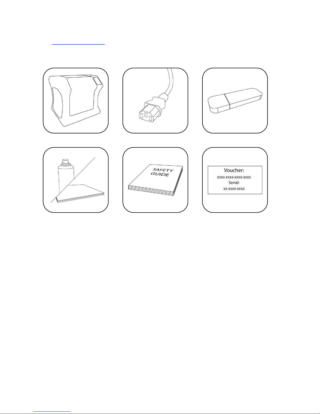
1.3 WHAT IS IN THE BOX
Bolt Pro Pro 3D Printer
Power cable
USB stick
Bed adherence
Safety guide
Software Voucher*
*You may receive the software
voucher electronically
Page 8

8
1.4 VIDEO GUIDES & TUTORIALS
To get your new printer up and running we have produced a series of short video guides
& tutorials covering the following topics:
1) Unboxing
2) Calibrate
3) First Print
4) Remote Access
5) Soluble Support
6) Flexible Material
7) Swapping Filaments
8) Swapping Hot Ends
Page 9
9
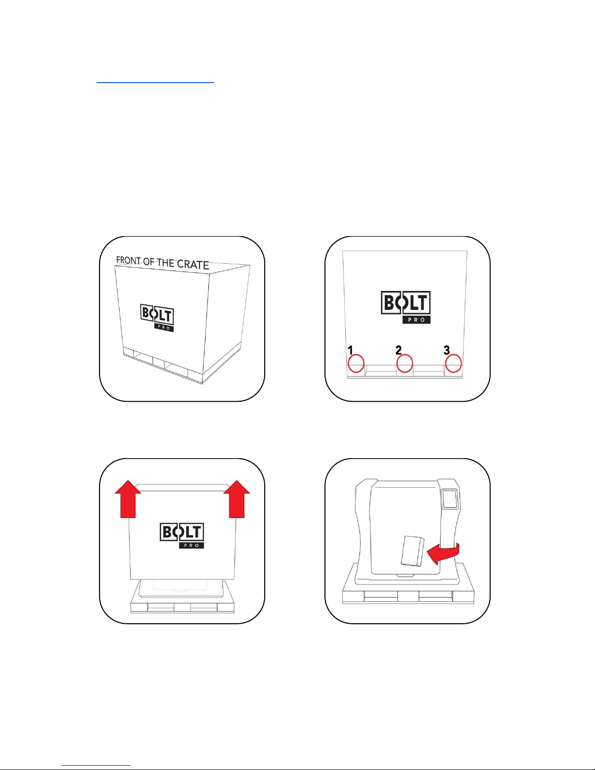
1.5 UNBOXING THE PRINTER
Before beginning to unbox the printer please check the shipping create for any signs of
damage.
It is important to carefully unbox the printer according to the instructions. You will
require two people for this task.
Inspect the create for any signs of
damage.
Screw holes are indicated with arrows.
Remove a total of 6 screws from the
front and back of the crate.
Lift the top of the box upwards this
requires two people.
Remove the box containing the power
cable and other accessories.
Page 10
10
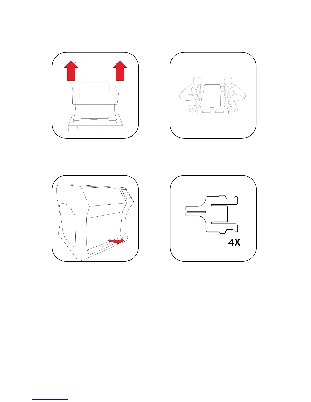
Remove the cover protection on the
outside of the Bolt Pro.
Place the Bolt Pro securely on a table or
workbench. This requires two people.
Open the door
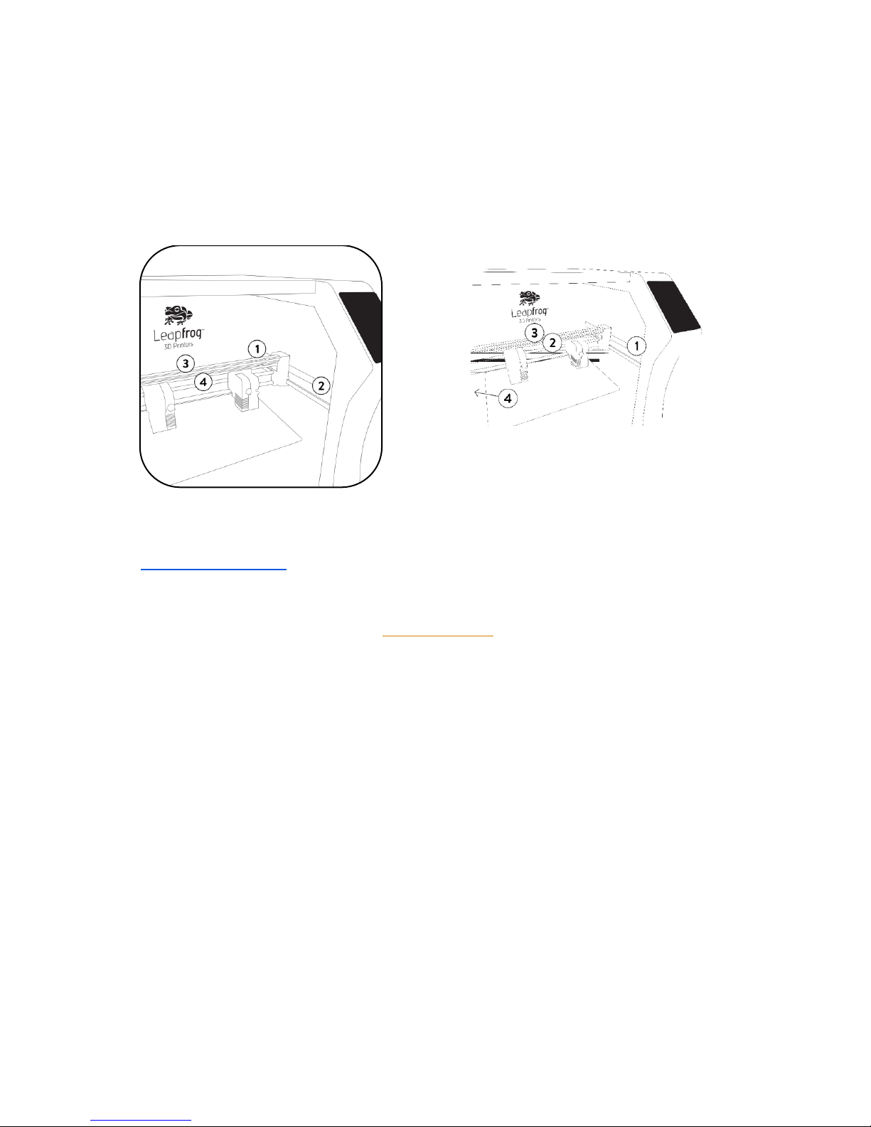
There are four transportation clips on
the inside of the printer.
Page 11
11
Remove any remaining protective film from the interior & exterior of the printer.
CONGRATULATIONS!
You have now successfully unpacked your Bolt Pro 3D Printer!
If you have not already watched the tutorial videos please do so now.
Alternatively, follow the instructions from the Quick Start Guide or shown on the User
Interface, to start your first 3D print!
One clip located on either side of the
printer lock the left and right Y-axis
belts in place.
Two further clips on the X-axis. Each
locking one of the X-axis belts in
place.
Get the power cable and plug this in the
back of the printer and plug the other end
in a grounded (!) wall outlet.
Page 12

12
1.6 ELECTRIC POWER CORD COMPATIBILITY
Please check the power cord that came with the printer to see if the plug matches the
electrical wall outlet that your country typically uses. The Bolt Pro has a power supply
unit that is switched-mode capable – meaning it will automatically switch between
allowed voltage input between 100 volts and 230 volts. However, make sure that the
correct power chord has been supplied along with your printer.
If this is not the case, please go to our website and open a support ticket, attaching a
copy of the printer’s original purchasing invoice and a photo of the power cable that
came with the printer; our Technical Support Team will place an order for the correct
power cable as soon as possible.
Once you have confirmed that you have the correct power cord, please connect the
power cord to the back of the Bolt Pro in the appropriate slot and plug the other end
into a grounded wall outlet. Failing to make sure that you have a grounded wall outlet
can result in the printer possibly being damaged by an electric power surge. In addition
to using a grounded power outlet, it is also recommended to use a surge protector.
At this point, you can safely turn on the power switch on the back of your printer.
Page 13
13
2 ABOUT THE BOLT PRO
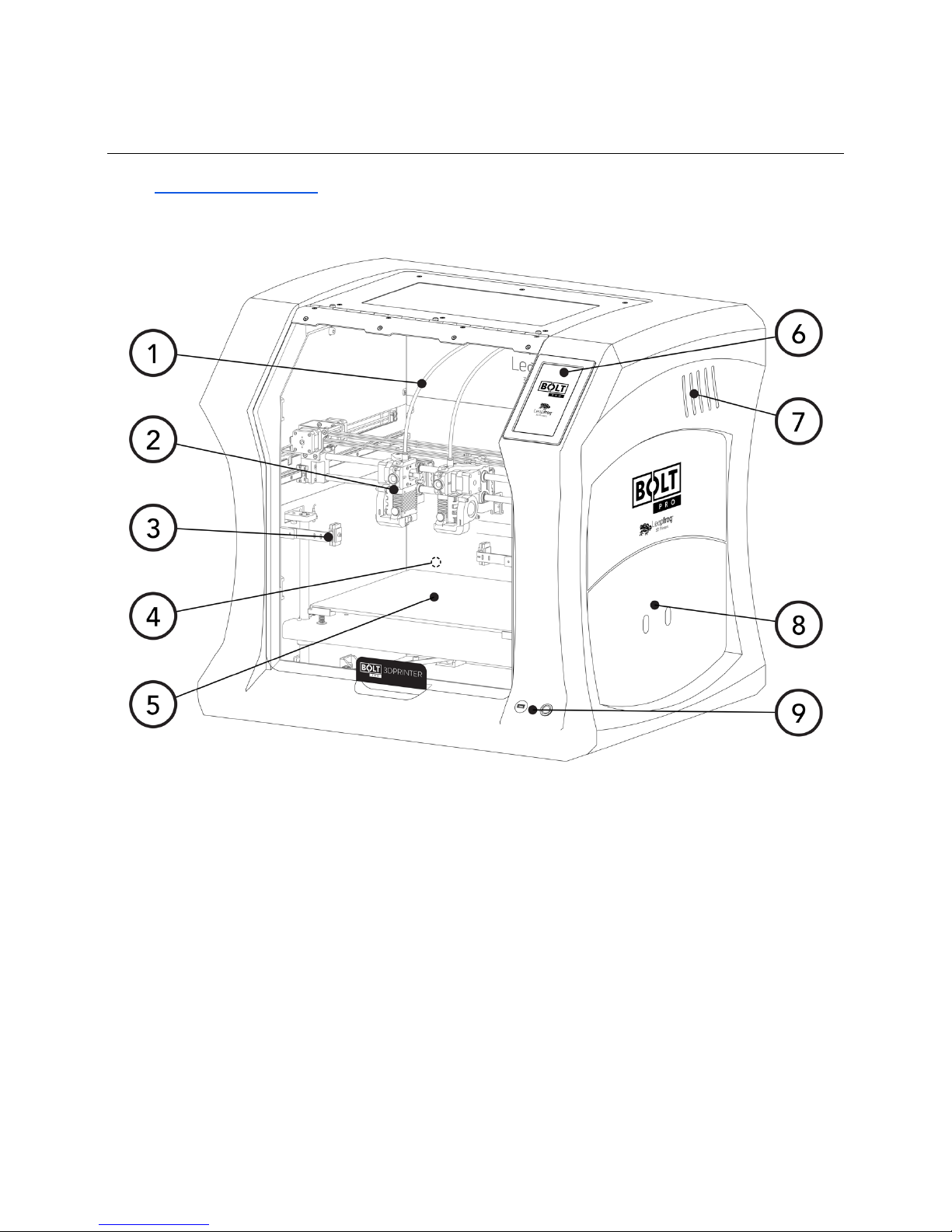
2.1 BOLT PRO OVERVIEW
1. Filament guide tube
2. Printhead (one of two)
3. Nozzle wiper (one of two)
4. Power switch (on the back of the Bolt Pro)
5. Print bed
6. Touchscreen
7. Activated HEPA Carbon filter vent
8. Filament compartment
9. On/off button and USB port
Page 14
14
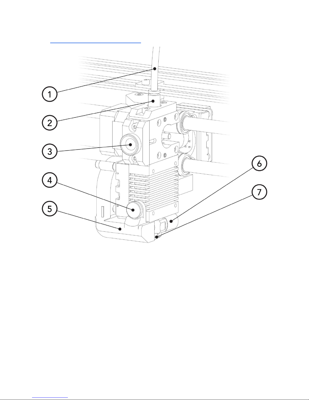
2.2 BOLT PRO PRINTER HEAD OVERVIEW
1. Filament guide tube
2. Push-in coupling
3. Filament pinch wheel (used to control the grip on loaded filament)
4. Hot-end thumb screw (used to swap hot-ends)
5. Fan-duct
6. Hot-end (includes also nozzle)
7. Nozzle
Page 15
15
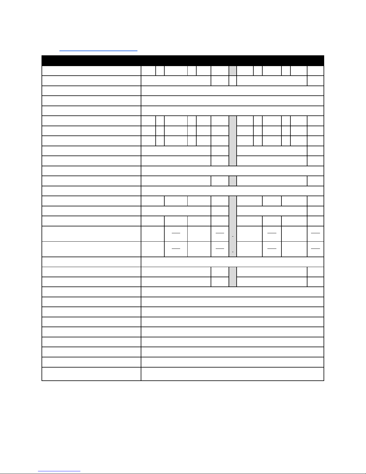
2.3 BOLT PRO SPECIFICATIONS
Specification
Metric
Imperial
Physical dimensions (DWH)
723 x 831
x
801
mm 28.5 x 32.7
x
31.5
inch
Printer weight
61
kg
134
lbs
Input voltage range
88-264VAC
Input frequency
47 - 63 Hz
Power consumption
600W
Build size single extruder (DWH)
320 x 330
x
205
mm 12.6 x 13.0 x 8.1
inch
Build size dual extruder (DWH)
320 x 300
x
205
mm 12.6 x 11.8 x 8.1
inch
Build size replicator/mirror mode (DWH)
320 x 164
x
205
mm 12.6 x 6.5 x 8.1
inch
Build volume
21.6
L
4.8
gall.
Heated bed max temp
90
°C
194
°F
Closed chamber
Yes
Hot end Max temp*
360
°C
680
°F
Number of extruders
2
Extruder size(s)
0.35
mm 1.38E-02
inch
Filament size
1.75
mm 6.89E-02
inch
Layer thickness
0.05
to
0.35
mm 1.97E-03
to
1.38E-02
inch
Advised printing speed (DW)
6000
mm
min
100
mm
s
236
inch
min
4
inch
s
Max. travel speed (DW)
15000
mm
min
250
mm
s
591
inch
min
10
inch
s
Stepper motors
1.8° Step angle with 1/32 micro stepping
Positioning accuracy (DW)
0.008
mm 3.15E-04
inch
Positioning accuracy (H)
0.010
mm 3.94E-04
inch
Body/frame construction
Aluminum Framework
Heated bed construction
High-grade glass
Semi-automatic print bed Z-levelling
Yes
Ethernet connection
Yes
Wifi connection
Yes
Internal OS
Linux
USB standalone format
.Gcode format
Printing modes
Single, Dual Material, Replicator mode, Mirror mode
Open system print materials (*
experimental)
PLA, ABS, HIPS, Flex, Nylon, Hybrid, Woodfill, Scaffold, Carbon*, other*
DWH: Depth, Width, Height. Coordinate system reference Y, X, Z
A Low-temp (max 250 degrees) and High-temp hot end (max 360 degrees) is supplied
Page 16

16
2.4 LEAPFROG USER INTERFACE OVERVIEW
PRINT TAB
1. Software refresh.
2. Notifications area.
3. Power options.
4. Shows information about
the selected print job.
5. Shows a preview of the
selected print job.
6. Navigate to the Jobs tab to
select a print job.
7. Shows the temperatures of
the nozzles and bed and
gives access to the built-in
webcam live view.
8. Start a print job and select
the print mode.
9. Loads the wizard to load or
unload filament for the left
and right extruder.
10. Shows the current Print
tab.
11. Navigate to the Jobs tab.
12. Navigate to the Settings
tab.
Page 17

17
JOBS TAB
1. Software refresh.
2. Notifications area.
3. Power options.
4. Local and USB storage.
5. Search storage.
6. Manage storage.
7. Filename.
8. Print selected file.
9. Show information on file.
10. Additional information on
file.
11. Delete or copy a file to USB
or local storage.
12. Shows that the file is not
yet printed.
13. Shows that the file is
successfully printed.
14. Shows that the file wasn’t
successfully printed.
15. Navigate to the Print tab.
16. Shows the current Jobs
tab.
17. Navigate to the Settings
tab.
Page 18

18
SETTINGS TAB
1. Software refresh.
2. Notifications area.
3. Power options.
4. General printer
information.
5. Navigate to the
maintenance menu.
6. Add, edit or remove
materials.
7. Access built-in camera and
download captured time
lapses.
8. Add, edit or remove users.
9. Connect to wireless
network and check IP
address.
10. Update the Bolt Pro
software and firmware.
11. Navigate to the Print tab.
12. Navigate to the Jobs tab.
13. Shows the current tab.
Page 19

19
SETTINGS TAB
1. Moves both print heads to
the front of the Bolt Pro
for head maintenance.
2. Moves both printheads to
the back of the printer for
bed maintenance.
3. Change the amount of
filament on the loaded
spools.
4. Calibrate both extruders in
reference to each other.
5. Calibrate the print bed in
reference to the nozzles.
6. Purge left/right extruder.
7. Close maintenance menu.
Page 20

20
3 FIRST BOLT PRO EXPERIENCE
In order to start the printer, several setup steps have to be completed. These steps are
described in this manual in detail.
A shorter guide can also be found in the Quick Start Guide, delivered alongside your Bolt
Pro and with the User Interface Guide.
Bolt Pro LED’s
The Bolt Pro is fitted with RGB LEDs.
The default colour of the Bolt Pro lighting is blue, the colour will change depending on
the status of the printer. Each colour indicates a different function.
o Blue: idle
o Orange: heating
o White: printing
o Green: finished printing
3.1 YOUR FIRST 3D PRINT TUTORIAL
You can use the Your first print feature found on the Bolt Pro user interface. This will
prompt when first powering on the Bolt Pro or can be started manually.
This tutorial will guide you through the following steps:
NOTE Two spools of PLA filament are needed to successfully complete this guide.
1. Load filament
2. Calibrate the print bed
3. Calibrate the extruders
4. Start your first 3D print
START THE FIRST 3D PRINT TUTORIAL MANUALLY
To start the Your first print tutorial, go to Settings, Tutorials and choose Your first
print.
WHAT THE TUTORIAL DOESN’T SHOW YOU
The tutorial guides you through the needed steps to use the Bolt Pro using the
touchscreen. If you plan to use the Bolt Pro remotely, then it is needed to set up user
accounts and connect the Bolt Pro to the internet.
Page 21

21
4 PRINTER SETUP
Before you can start using the Bolt Pro, some preparation is required. Also, be sure to
read Chapter 1.5: Electric Power Cord Compatibility.
The following chapters should be followed to make the Bolt Pro fully operational and
print ready.
3.1 Setting up user accounts
3.2 Connecting the Bolt Pro to a network
3.3 Update the Bolt Pro
3.4 Calibrate print bed
3.5 Load filament
3.6 Add materials (if necessary for 3.5)
3.7 Apply bed adhesive
You will need to set up an admin user account in order to control the number of
privileges normal users have on the Bolt Pro.
Connecting to the internet is also highly recommended to fully use its auto-updates and
connectivity with your mobile phone and/or computer.
Calibrating the bed should be done at least once after transporting the Bolt Pro. The
wipers will need to be checked as well.
And finally filament should be loaded and the print bed should be prepared before each
print.
When operating the printer stand in front of the printer.
Page 22

22
4.1 SETTING UP ADMIN AND USER ACCOUNTS
The Bolt Pro is capable of having multiple user accounts, with different levels of access.
This is great for shared work environments. Remote control will only be accessible to
users with an account and those that do have access may be limited to what they can
do based on their account settings.
Setting up an Admin account is highly recommended before providing the Bolt Pro’s IP
address to the users in your office environment.
NOTE Replacing a forgotten password for an Admin account will be very difficult to do,
so please write it down in a location that you will be able to recover it if need be later
on.
To add a user, select the Settings tab and tap on the
Users menu option. Add an admin user and be sure
to set the check-box to green, next to Admin.
In the picture, you see that user admin has
administrative rights. The pencil icon allows editing
the user account and the trashcan icon for deleting
the user account.
The User Interface differentiates three kinds of users:
NOT LOGGED IN USERS These users can only upload files but cannot start prints from a
remote device.
LOGGED IN USERS These users can upload and print, but cannot change settings from a
remote device.
ADMIN USERS Admin users can also upload and print as well as change settings on the
printer from a remote device.
Page 23

23
To add a user, click the Add user button.
Use the touchscreen keyboard (by typing inside each
text field) to fill out the Username, Password, and
Repeat Password fields.
Make sure to indicate whether the user will have
administrative privileges or not by switching the slider
on green or red.
Confirm to create the account or Abort to cancel the
account creation.
4.2 CONNECTING THE BOLT PRO
The Bolt Pro Wi-Fi and Ethernet connectivity. Select
Settings, then Network to access the connectivity
settings. With the Wi-Fi enabled the Bolt Pro will scan
for available wireless networks, select the network
you wish to connect to and enter the security details.
This page will also display your Bolt Pro’s MAC address.
The Bolt Pro will automatically attempt to connect to
a network if an ethernet cable is inserted. Click the
small pencil button next to the IP address to access
the advanced network connection settings.
If you are currently connected to a network and wish
to change networks, you will need to first disconnect
from the current one by selecting the Disconnect
button.
Page 24

24
4.3 AUTOMATIC UPDATE FUNCTION
Because our R&D department is constantly improving the quality of experience that our
customers have with our 3D printers, they periodically provide new updates that further
improve the printer-user experience. For your convenience, these updates are made
available online and can be directly installed on the Bolt Pro, with minimal printer
downtime.
To update your Bolt Pro, go to Settings and press Update to Update to the latest version
available. Please ensure that you are connected to the internet to use this function.
4.4 CALIBRATE PRINT BED
The Bolt Pro is a machine that moves and extrudes on
the micrometre level and exposure to shipping and
transportation can cause the bed level to lose
calibration.
If the first layer doesn’t adhere to the print bed, the
whole print can move while printing, resulting in a bad
print. The right distance between the bed and the
nozzle prevents this from happening.
To level and calibrate the bed, go to Settings →
Maintenance → Calibrate bed.
Continue Calibration and the screen will show a top
view of the print bed with 4 squares in each corner.
Each of these squares represents a position on the print
bed used for calibration.
The recommended distance
between bed and nozzle is
around 0.15 mm or roughly the
thickness of a standard sheet of paper.
Choose a corner position on the screen and find the knob
underneath the bed at the corresponding position. Turn this knob
clockwise to raise the bed, and counterclockwise to lower the
bed.
Page 25

25
Hold a piece of paper between the nozzle and print
bed and raise the bed until the paper is slightly
pinched between the bed and nozzle. Repeat this until
all four corner nozzles have the same distance from
the bed. And repeat this once more to confirm that all
nozzles are calibrated correctly.
4.5 LOADING/UNLOADING FILAMENT
Filament is the material what the Bolt Pro uses to
print. The extruder on the right side is treated as the
default/main extruder.
We recommend Leapfrog filaments and preferably PLA for the first loading process and
prints.
The filament will be loaded in the right side of the Bolt Pro and guided via tubes to the
designated print head. The filament will be melted in the print head and printed to the
print bed.
In the following steps, we will swap the Right filament. Swapping the Left filament will
follow the same process.
NOTE The printhead assembly will perform some forceful movements during this
process. Please keep all body parts or objects clear when this movement occurs to
prevent injury or damage to the machine.
Page 26

26
STEP 1
Locate the coloured push-in coupling on the right print
head, connecting the print head to the filament guide
tube. Remove the tube from the printhead by pushing
the coupling down and pulling tube upwards in the
opposite direction. Leave the tube disconnected until
the filament is loaded correctly.
STEP 2
On the Bolt Pro User Interface,
select the Print tab and choose the
Swap Right option for the right
extruder.
It will ask you to confirm the unload
process; please do so.
NOTE The printer will first pre-heat the selected nozzle to help load and unload
filament. This is will extend the life of your nozzle blocks and will help prevent clogs.
STEP 3
You will then be prompted to physically unload and roll off the filament spool that was
previously loaded in the printer, if applicable. To do this, open the filament
compartment on the right side of the Bolt Pro and remove the filament spool from the
filament compartment. The right extruder will then be empty and available for loading
a different spool of filament.
Page 27

27
STEP 4
After unloading the previous roll of
filament (if applicable), the software will
ask which type of filament is to be loaded
into the extruder.
Select the right material from the drop
menu. If the correct material isn’t listed,
select abort and add an additional
material. This can be done in the in the
Settings tab under Materials, as explained
in the next chapter.
NOTE Some high-performance filaments
need a higher extrusion temperature.
When a Hot End is loaded which isn’t able
to reach the desired temperature, the Bolt
Pro will let you know that you need to swap
for a High-Temperature Hot End.
Select how much filament is on the spool.
This way, the Bolt Pro knows whether or
not there will be sufficient filament to
print the selected print job and will notify
you when there will not be enough. Keep in mind that this is as accurate as the user can
determine the amount of filament left on the spool, so it will be an estimate.
NOTE For swapping both the Left and Right extruder in succession, you can pre-heat
both nozzles under Settings → Maintenance → Head maintenance.
STEP 5
In order to help the filament feed through the machine, clip the end of the filament to
where it forms a point and then use your fingers to straighten the filament out. Being
wound around a spool, the filament has a natural bend; straightening just the first few
centimetres out helps to prevent the filament from
catching when it reaches a filament tube coupling.
Begin feeding the filament through the correct filament
tube port on the right side of the printer. For loading
filament into the right extruder, the right filament
compartment must be used, for the Left extruder, the
left.
Page 28

28
When feeding the filament to the filament entry port, ensure that the filament is rolled
correctly off the filament spool. The filament should be rolled from the bottom of the
spool into the entry port. If the filament is loaded incorrectly, then the loaded filament
can get damaged while printing and clog the nozzles.
NOTE Some filaments such as Nylon and Scaffold have special properties that make them
susceptible to things like air moisture or sunlight. Please take extra care of these types
of filaments, making sure not to leave them in the printer or outside of their protective
packaging. Scaffold, in particular, should always be unloaded from the printer
immediately after use to help prevent clogging of the nozzle.
STEP 6
Feed the filament through the filament entry port; keep
feeding until you see the filament in the translucent
filament guiding tube reach all the way print head
filament drive gear. Make sure that the filament is fed
past the end of the tube.
If you haven’t disconnected the guiding tube in Step 1,
you can choose to disconnect the guiding tube now. Now
you can help feed the filament through the drive gear.
Do this by gently pushing the filament down the top of
the print in the coupling to the drive gear.
STEP 7
When the extruder is preheated, you will be prompted to
confirm that you are ready to load the filament. Press
the Load button and the print head will begin feeding
filament. While the drive gear in the print head will start
turning in order to feed filament, keep feeding filament
by hand if needed and apply a little pressure in order for
the drive gear to grip the filament. Repeat this until the
filament is gripped by the drive gear.
STEP 8
The filament will be correctly loaded if the nozzle extrudes filament by simply pressing
‘load more filament’ on the User Interface. Connect the tube if applicable by pushing
the guiding tube back in the pushing coupling.
Page 29

29
4.6 ADD MATERIAL
Materials in the Bolt Pro software are used to pre-heat
and prepare the Bolt Pro for loading and unloading
filament. The materials print settings are set in the Gcode.
When a material isn’t available when loading filament,
it can be manually added. To see what materials are
available, or if you would like to add an additional
filament, go to Materials under the Settings tab.
A list of materials is visible under Materials and adding
a material can be done with +Add profile.
When adding a material, fill in a profile name and add
the correct temperatures to complete the material
profile. Press save to store changes and start using the
profiles.
4.7 ADHESIVE MATERIAL
The print surface on the Bolt Pro is glass. Bed adhesive
is required to ensure prints stick correctly to print bed. While
over options are available Leapfrog recommend 3D spray as we
find this to provide the best results.
NOTE Failing to ensure that a print is sticking to the bed for at
least the first few layers could result in a large mass of filament
collecting on the tip of the nozzle and can severely damage the
printer. Though we don’t expect the print to be monitored from
beginning to end, we strongly advise monitoring the first critical
layers of the print. Using the built-in webcam enables the user
to monitor the printing process remotely.
Page 30

30
5 PRINTING
The Bolt Pro requires a G-code file to print. G-code files are lists of instructions which
the printer will follow to build up the 3D part which has been sliced with the included
slicing software, Simplify3D.
The following will be covered in this chapter to print generated G-codes:
4.1 Starting Print jobs
4.2 Finishing Print jobs
4.3 Using different printing modes. Sync mode and Mirror mode
4.4 Information available on print jobs
4.5 Accessing and storing print jobs
5.1 STARTING PRINT JOBS
To make a 3D print, three things are required. Filament, a 3D file in G-code format and
a 3D Printer. Creating a G-code from an STL is explained in the next chapter. To start
your first print, you can use the pre-installed file on the storage of the Bolt Pro. Choose
PLA as filament for the Bolt Pro example print.
NOTE When starting a print, it is strongly advised for the user to know that the filament
is loaded correctly, the bed is correctly calibrated and the print bed is supplied with
adhering material like 3D Spray or a print sticker. This is explained in the previous
chapter.
The following steps will be explained below:
1. Start-up the Bolt Pro
2. Prepare the print bed
3. Select the print job
4. Select ‘Start print’.
5. Wait until the Bolt Pro is heated up and starts printing its first layers.
STEP 1
Start the Bolt Pro and load filament in the Bolt Pro as explained in the previous chapter.
Navigate on the Bolt Pro User Interface to the Print tab.
STEP 2
Prepare the print bed with necessary adhesive. This is explained in chapter 4.7.
STEP 3
Press ‘Select print job’ to navigate to the internal storage of the Bolt Pro. Here all prints
on the Bolt Pro are located, as well as the linked USB storage device. Select the file you
Page 31

31
want to print by navigating to the Print tab and pressing the ‘play’ button or ‘Print’ at
the bottom of the screen.
NOTE Trying to run a G-code file that was not designed for the Bolt Pro and filament
type that you have loaded will result in a failed print, most likely a clogged extruder
and can damage the hardware of the Bolt Pro. Ensure that you have used the latest and
correct profiles in the Simplify3D software these can be downloaded from the Leapfrog
website.
STEP 4
Press ‘Start print’, select the desired ‘printing mode’ (for the first sample print, we
advise ‘normal’) and press Start Print.
STEP 5
The Bolt Pro will start heating its extruders to the correct temperature. Afterwards, it
will begin moving its head and start extruding filament on to the bed. The first couple
of layers is critical for a successful print.
CALIBRATE ON THE FLY
For more advanced users; during the first layers, the bed height can still be adjusted
using the knobs underneath the bed. This way you can ensure that your print will have
a great start for a successful finish. Remember that turning the bed calibration knobs
clock-wise raise the bed. Counter-clock-wise lowers the bed.
NOTE A scratching sound can indicate that the inactive nozzle can be touching the print
bed. This means that the nozzle and bed are getting damaged. Be sure to lower the
print bed slightly by turning the bed calibration knob counter-clockwise.
Page 32

32
5.2 FINISHING PRINT JOBS
The User interface will indicate when the print is completed.
The following steps can be followed to successfully remove the print and prepare the
Bolt Pro for future print jobs.
1. Check if the print is done printing
2. Remove the print from the print bed
3. Clean the print bed.
STEP 1
A notification on the top of the Bolt Pro software telling the user that de Print is
finished. Pressing the notification will remove it from the screen and the print can be
removed from the Print bed. The notification will also be visible on another device if
the user was still logged into the printer.
STEP 2
Carefully remove the print bed from the printer and place on a flat surface. A spray
bottle containing water can be used to aid in the removal of printed parts. Waiting a
couple of minutes will let the water dissolve the 3D Spray, releasing the print from the
print bed.
The print might still be strongly adhered to the print bed so apply gradually apply force
if necessary.
STEP 3
Clean the print bed of any debris and leftover filament sticking to the print bed. A (nonmetal) putty knife or similar tool can be used. If you are using a metal putty knife or
something similar, be careful not to damage the print bed.
Take care when using any tool when cleaning a debris from a print sticker, as it can
damage the sticker.
Page 33

33
5.3 USING DIFFERENT PRINTING MODES
The Bolt Pro is fitted with two independent print heads. These Independent Dual
Extruders can work in three different modes. NORMAL both heads work together to print
a multi-material or multi-colour print. SYNC mode, both print heads print an identical
part. MIRROR mode, both print heads print a mirrored part.
PRINTING MODE BED PLACEMENT
When printing in Sync or Mirror mode, the Bolt Pro will automatically duplicate or mirror
your G-code and part. Therefore, only half of the build volume can be used when slicing
an STL to G-code. When creating a G-code suitable for Sync and Mirror mode, be sure
to place the part or parts on the Left half of the Print bed.
Page 34

34
NORMAL MODE
Pro:
Dual material/Dual colour
Full build volume
Larger objects
Con:
Normal production speed
In Normal printing mode, the Bolt Pro can print either single extrusion or dual
extrusion prints and the full build volume can be used.
Dual-material or dual-colour printing is selected from within the Simplify3D slicing
software.
If printing with a single material or colour only the selected print head needs filament
loaded. If printing a dual extrusion print, both left and right printheads will need to be
loaded.
SYNC MODE PRINTING
Pro:
Double production speed
Make a copy of the print
Used for multiples of 1 print
Con:
Single material/colour
Reduced build volume
Smaller objects
Sync mode printing will use both print heads simultaneously to print two identical
parts.
In Sync mode the available print area will be halved since the Bolt Pro will have to
print the same object twice. Both extruders will be used so both the Left and Right
filament should be loaded.
Printing in sync mode will require a G-code file set on the correct left half of the print
bed. The Bolt Pro will copy the G-code automatically to the other half of the print
bed.
MIRROR MODE PRINTING
Pro:
Double production speed
Make a mirror copy of the print
Used for symmetrical prints
Con:
Single material/colour
Reduced build volume
Smaller objects
Mirror mode printing will use both print heads simultaneously to print two mirrored
parts.
The difference with Sync mode printing is that the print will be not be copied but
mirrored in the X-axis. This can be useful when making moulds or symmetrically shaped
objects.
In Mirror mode the available print area will be halved since the Bolt Pro will have to
print an additional mirrored copy of the selected print. Both extruders will be used so
both the Left and Right filament should be loaded.
Page 35

35
Printing in Mirror mode will require a G-code file set on the correct left half of the print
bed. The Bolt Pro will copy and mirror the G-code automatically to the other half of the
print bed.
5.4 INFORMATION AVAILABLE ON PRINT JOBS
The Bolt Pro analyses print jobs uploaded to its internal storage.
The Bolt Pro will let the user know which nozzle is set in the G-code, as well as how
much filament will be needed. If the amount of filament left on the loaded filament
spool is less than needed, then the Bolt Pro will disable the start print function,
preventing the user to start printing an incomplete print.
It will also give you a rough preview of the selected print job as well as an estimation
on how much time it will take printing it.
5.5 ACCESSING PRINT JOBS
The Bolt Pro has internal storage for G-code files. This storage can be accessed on the
Bolt Pro or on your computer, phone or tablet using Wi-Fi. The Bolt Pro has a USB port
as well.
Accessing the Storage can be done via the Jobs tab in the bottom of the screen. Here
you can access the local storage, USB storage and search for a print.
5.6 UPLOADING PRINT JOBS: USB
When plugging in a USB storage device, you will be prompted to browse the USB files.
You can also access the USB on the top of the Jobs tab. On the USB storage, you can
navigate to the desired file and upload it to the Bolt Pro.
5.7 UPLOADING PRINT JOBS: NETWORK AND WIFI
To upload prints to the Bolt Pro using Wi-Fi, the Bolt Pro has to be connected to the
same network as your computer. In the wireless menu, an IP address can be found. Place
this IP address into your browser as you would a website URL to access the Leapfrog
User Interface of the Bolt Pro. Login to get the right privileges and upload files in the
Jobs tab.
For more information on accessing the Bolt Pro via your network, see to chapter 6.3
Page 36

36
6 CREATING A PRINTFILE WITH SIMPLIFY3D
When using Simplify3D to prepare a G-code file, ensure you have the correct and most
recent material profiles. This can be downloaded from the support section of the
Leapfrog website. Print Settings.
DO NOT use the included profiles included with Simplify3D. These settings are not
produced or maintained by Leapfrog.
To create a G-code for the Bolt Pro, a digital 3D model will need to be imported into
the software. A commonly used, and broadly accepted file type is an STL file type.
NOTE Creating a 3D model is not explained in this tutorial. Free 3D model STL’s can be
found online, as well as free 3D modelling tools.
Creating a G-code from an STL means that the Simplify3D will slice the 3d model into
separate layers, for the printer to build the 3D model layer by layer. Another commonly
used word for a program like this is therefor a ‘slicer’. For more information on 3D
printing and slicing, see the Learn section of the website and follow the free courses.
6.1 SIMPLIFY3D
Simplify3D is a professional third party piece of software. It is not produced by Leapfrog.
Leapfrog provides one full licence which can be used on two separate computers.
Install the Simplify3D software on a computer which meets the minimum requirements
and create or download the desired STL file that you want to print. For more information
on Simplify3D refer to the Simplify3D User Manual:
Simplify3D provide tutorial videos and courses on their website here. The below is a
very basic overview of the software, it is therefore recommended to watch and read
through the provided guides.
Page 37

6.2 CONFIGURATION ASSISTANT
When you open Simplify3D for the first time,
you will be greeted by the Configuration
Assistant. This can also be found at any time
under Help, Configuration Assistant.
Select the Bolt from the drop-down menu.
Page 38

38
6.3 SIMPLIFY3D INTERFACE LAYOUT
After configuration is complete, the following interface will be shown. From here you
will be able to import, adjust and process your 3D model ready for printing.
6.4 PREPARE YOUR 3D PRINT
Obtain a 3D model either created in a CAD program or download one from a repository
such as Thingiverse. The file type should be .stl or .obj.
Click Import in the Models section and click “centre and arrange” to automatically
distribute your model (s) to the centre of the print bed.
Page 39

6.5 PROCESS YOUR 3D PRINT
The selected Process will determine how Simplify will slice the 3D model. The
Configuration Assistant should have created ‘Process1’, which will be suitable for most
prints.
Editing processes can increase the print quality greatly. Advanced parameters can be
altered here alongside basic process settings. The basic settings are FFF Settings are:
SELECT PROFILE
This loads a printer profile with corresponding settings.
AUTO-CONFIGURE FOR MATERIAL
This will adjust the temperature, extrusion and cooling settings based on the select
filament.
AUTO-CONFIGURE FOR PRINT QUALITY
This will adjust the layer-height, infill density and other quality settings based on the
level you desire.
AUTO-CONFIGURE EXTRUDERS
Here you can select the extruder you want to print with. In this manual, we use the
right extruder as a default.
INFILL PERCENTAGE
Adjusts the solidity of the print. 0% infill will create a hollow model where 100% will
create a solid model. This can increase, or decrease the print time greatly and we advise
you to use a value in the range of 15-25%.
INCLUDE RAFT
A raft is an additional structure which will increase the bonding of your print with the
build platform. This will not be needed for most prints.
GENERATE SUPPORT
This will automatically generate break-away support for your 3D print.
For more information about support, slicing and other 3D printing techniques and
knowledge, we advise you to follow our free online courses. These can be found in the
Learn section of the Leapfrog website.
Page 40

40
6.6 PREVIEW YOUR 3D PRINT
After finalizing the print settings, you can go to ‘Prepare to Print!’. This will initiate a
preview of how your 3D print will be printed.
The preview mode will render the exact movement the printer will make, allowing you
to preview how the model will be constructed. This can give you information about the
end result beforehand and experienced users will use this feature intensively.
Preview mode will provide two interactive buttons:
PLAY/PAUSE
Play or pause an animated print preview.
START AND END SLIDER BARS
Move manually through the animated preview.
On the top left Simplify3D will show Build Statistics which are the Build time, used
filament length, weight and an approximation of the material costs.
6.7 PRINT
To start printing, save the generated g.code for printing by choosing Save Toolpaths to
Disk. This file can then be transferred to the Bolt Pro using a USB drive or via the network
connection.
Page 41

7 LEAPFROG USER INTERFACE
The comprehensive and intuitive User Interface allows the user control printing,
maintenance and the internal storage of the Bolt Pro.
For a quick overview of the Leapfrog User Interface, see to chapter 2 of this manual.
For more information on how to use the software for printing, see to the chapter
‘Printing’.
7.1 LEAPFROG USER INTERFACE FEATURES
The User Interface provides the user control of the Bolt Pro when printing and keeping
the printer in good condition. In the settings tab, the Bolt Pro can be calibrated and set
in certain positions to help the user maintain and clean their Bolt Pro.
The User Interface is accessible via other platforms like a phone, tablet and computer
and can update automatically. When connected to the Bolt Pro with a remote device,
the user can download and upload files, stored on the Bolt Pro. The built-in webcam
can be accessed as well and time-lapses can be made and downloaded from the Bolt
Pro.
When uploading files, the Bolt Pro will analyse the file to provide useful information as
printing time and needed filament. When the Bolt Pro sees that the amount of filament
exceeds the amount filament left on the spool, it will tell the user.
7.2 STATIC IP AND CUSTOM DNS SERVERS
In order to connect your printer to the internet and let people from outside your network
accconnect to the printer, it is useful to give the printer a static IP.
To do so, go to the Wireless menu under Settings. Connect to the dedicated network
and when connected, press the pencil icon to set a static IP address and custom DNS
server settings.
For detailed information about your specific IP address and DNS settings, please contact
your IT expert.
7.3 REMOTE ACCESS AND USER PRIVILEGES
The Leapfrog User Interface can be controlled using the touchscreen on the machine,
or with another device equipped with network capability and a browser. This also
enables the user to use the webcam’s live view function.
Using the Bolt Pro from the touchscreen will give the user full access to its functions
and capabilities. Accessing it remotely will restrict the user with certain functions
depending on the assigned privileges from the account. The different types of users are;
Page 42

42
NOT LOGGED IN USERS These users can only upload files but cannot start prints from a
remote device.
LOGGED IN USERS These users can upload and print, but cannot change settings from a
remote device.
ADMIN USERS Admin users can also upload and print as well as change settings on the
printer from a remote device.
Page 43

7.4 REMOTE ACCESS TO THE BOLT PRO
NOTE The following chapter will describe how to access the Bolt remotely using your
personal network.
Connecting to the Bolt Pro via a remote device can be done using the following steps.
1. Connect the Bolt Pro to your network
2. Find the IP address of your Bolt Pro
3. Connect your device to the same network
4. Open the IP address in your preferred browser
5. Log in with your user account
STEP 1
Connect the Bolt Pro to the network using Ethernet or Wi-Fi. When using Ethernet, use
an Ethernet-cable to connect the Bolt Pro directly to the router.
When using Wi-Fi, connect the Bolt Pro to the Wi-Fi network using the Settings →
Wireless tab, as explained in the chapter ‘Printer Setup’.
STEP 2
Go to Settings on the Bolt Pro and go to Wireless. If the
Bolt Pro is connected correctly to the network, there
will be a number shown in the top right corner consisting
of 6 to 8 numbers. In this example, we will use the IP
address 192.168.0.25.
This is the IP address your network has allocated to the
Bolt Pro when it connected to the network and which
will be used to connect the remote device to the Bolt
Pro.
STEP 3
Go on your preferred device with network capabilities
and a browser and connect it to the same network as the
Bolt Pro.
STEP 4
Open your preferred internet browser on the remote device and type in the IP address
you have found in the Wireless menu of the Bolt Pro.
The browser should start up the Leapfrog User Interface of the Bolt Pro on your device.
Page 44

44
STEP 5
In order to be able to print or change settings, the remote device should be logged in
to the admin or similar privileged user account.
To log in, click login in the top right corner of the screen and fill in the correct username
and password.
7.5 USING THE WEBCAM
The Leapfrog User Interface can access the built-in
webcam to view the current print job or create a time
lapse of your print.
There are two places where you can access the
webcam. On the print screen go to info, and click Live
stream to see a live stream of the built-in webcam.
To access the webcam, go to Settings → Webcam, to
open the webcam screen.
Here a current view of the webcam will be shown as a
picture, which can be refreshed. Livestream can also
be selected to view a live stream of the current print
job.
To create a time lapse, the Timelapse settings must be
enabled before starting a print job. Afterwards, the
timelapse can be found under ‘Finished time-lapses’
were they can be saved or deleted from the Bolt Pro.
7.6 PURGE NOZZLES
This function can be used to purge the nozzles of excess or old filament. This can be
useful when cleaning the nozzles and keeping them in good condition.
7.7 MATERIALS
Under Settings →Materials different types of materials and filament can be added,
edited and removed.
The Bolt Pro pre-heats the nozzles before purging, cleaning and swapping filament.
Different filaments have different nozzle temperatures. Setting the temperature per
type of material correctly helps prolong the life or your nozzles and will reduce the
possibility of clogged nozzles greatly.
Page 45

8 MAINTENANCE & TROUBLESHOOTING
Please refer to the Maintenance Schedule available from Support section for the
Leapfrog website for a comprehensive guide to machine maintenance.
8.1 INSTALLING UPDATES
The Bolt Pro can update automatically when connected to the internet. Be sure to check
regularly in the Settings tab if an update is available. The number of updates available
is indicated by the number shown in the red circle.
To update, go to Update in the Settings tab, and press refresh in the top right corner.
Then, press update to update the Bolt Pro.
8.2 PRINTHEAD MAINTENANCE
Printhead maintenance has multiple features which help you work with the print heads
and keep them in good working order.
FILAMENT SETTINGS
Here you can quickly swap filaments without the “swap left/right” option. To swap
filament follow the following steps:
1. Pre-heat the designated nozzle
2. Unload the filament
3. Select the correct filament material, if applicable
4. Manually load the selected filament
PRE-HEAT
This will heat the print head to the set temperature of the loaded filament material
type.
UNLOAD
This will retract filament into the print head, allowing you to unload filament quickly.
PURGE
This will extrude a certain amount of filament. This can be used to load filament quickly
or clean the print head of filament which has been contaminated in any way.
SWAP HOT ENDS
This will move both print head to the front of the Bolt Pro. Now you can loosen the hot
end thumb screw on the print head and disconnect the hot end at the back of the print
head. The current Hot End can now be replaced.
This is not the advised method so use this method at your own risk.
Page 46

46
8.3 CLEANING THE PRINT BED
The print bed should be completely clean before starting the next print.
The 3D Spray adhesive and debris can be removed using a detergent like a window
cleaner and a putty knife. Scrape the filament debris away with a putty knife and clean
the free platform with a mild detergent.
8.4 CLEANING THE EXTRUDERS
In case of a clogged nozzle, heat up the clogged nozzle as if you were swapping filament.
Try to unload all filament from the extruder. Afterwards, wait until the extruder is
properly heated and re-load filament into the extruder.
8.5 REPLACING THE EXTRUDERS
Hot End’s degrade over time, this can be affected by the type of material used in them.
To replace the Hot End, unscrew the lower thumb screw on the front of the print head.
Disconnect the Hot End connector from the print head PCB.
8.6 LEVELLING EXTRUDERS
Perform bed calibration and calibrate the bed on the four corners. Position the print
heads at the centre position and get a sheet of paper, of a spacer of 0.150mm. Place
the spacer, or piece of paper, between the bed and nozzles. Unscrew the lower
thumbscrews of both heads, loosening both Hot End and dropping them on the spacer.
Tighten both thumbscrews when both extruders are down on the spacer to level both
extruders.
Page 47

8.7 CALIBRATE PURGE WIPERS
The height of the Purge Wipers should be checked after
calibrating the Hot Ends to the bed. Before and after each
layer, the Bolt Pro will purge its nozzle to remove any excess
filament to prevent oozing and leakage of filament on the
printed part. The wiper height should be gently touching the
nozzles.
When the wipers are too low or too high, purging won’t be
effective, resulting in strings and oozing your printed parts
which need to be removed afterwards.
To adjust the height of the wipers, you can unscrew the wiper
from its holder. Then the wiper can be adjusted by either
widening the hole in which it is fastened or cutting the top of
the wiper to the correct height.
When the wiper is at the right height, fasten the screw holding
the wiper in place.
Page 48

48
9 CONTACT & ADDITIONAL SUPPORT
9.1 TECHNICAL SUPPORT INFORMATION
Keep in mind also that we have an eager and experienced Technical Support Team
standing by to assist you with any questions you may have. If you are new to 3D printing
we have great online courses these can be found on our website’s Learn tab. Our Support
Team works best through our ticketing system and regularly updated solution articles,
both found on our website’s Support tab.
To open a ticket you will need to set up an account (which is a free, and fast process),
you will then be able to open a new ticket direct to our support agents, who are eagerly
awaiting to assist you. In the ticketing system, up to 15MB of files can be sent per
message allowing Technical Support to send you links, photos, videos, test G-code files,
and more. You too could upload photos and videos of your technical issue to better
describe what is happening. Customers have praised our ticketing system in the past as
being fast, chat-like, and a quick method of resolving any questions or issues that they
had.
We also offer live messaging chat – when agents are available – that can be accessed by
logging into the ticket system.
Questions can also be answered over the phone. We advise you to create ticket
beforehand and have your ticket number nearby. Simply give us a call: +31852080825
between the hours of 9:00 AM – 3:30 PM CET, Monday through Friday. At the time of
writing this manual, we do not have a toll free phone number.
When leaving a message for a phone appointment, it is advised to have a ticket created
as well.
Page 49

Company Information
ADDRESS
Leapfrog 3D Printers
H. Kamerlingh Onnesweg 10 / PO BOX 252
2408 AW Alphen aan den Rijn
The Netherlands
ONLINE
Website: www.lpfrg.com
Courses: courses.lpfrg.com
Facebook: https://www.facebook.com/lpfrg
Twitter: https://twitter.com/Leapfrog_3D
Instagram: https://www.instagram.com/leapfrog_3d/
Youtube: youtube.com/c/Leapfrog3DPrintersBV
Website blog: http://www.lpfrg.com/en/blog
CONTACT
General
info@lpfrg.com
+31 172 50 36 25
Support
support@lpfrg.com
+31 852 08 08 25
Sales
sales@lpfrg.com
+31 172 50 36 24
COMPANY INFORMATION
Chamber of Commerce
The Hague: 28040550
VAT: NL006608565B01
BIC: RABONL2U
IBAN: NL19 RABO 0317 4454 05
Rabobank Walcheren/Noord Beveland
Account nr: 3174.45.405
 Loading...