

Page 1
LEAP FORWARD
Leapfrog 3D Printers
User Manual
Version 1.68
Page 2

Page 3

DEAR VALUED CUSTOMER,
Thank you for purchasing the Leapfrog Bolt 3D Printer. We strive to make our machines
as easy to use as possible, but printing 3D objects invites a lot of creativity. New
solutions and unknown problems often require the user to stretch the limits and
capabilities of their machines. This manual ensures that you will achieve the best results
with your printer.
Please take the time to read through this manual as it was designed to help you get
familiar with your new printer and get you on your way to creating great looking 3D
models.
Keep in mind also that we have an eager and experienced Technical Support Team
standing by to assist you with any questions you may have. If you are new to 3D printing,
sometimes it is better to ask before trying something you are unsure of. Our Support
Team works best through our ticketing system and regularly updated solution articles,
both found on our website under support.
We hope that you enjoy your new Bolt 3D printer, and look forward to providing
assistance in any way we can.
Sincerely,
Your Leapfrog Customer Support Team
CONTACT INFORMATION
General
info@lpfrg.com
+31 172 50 36 25
Support
support@lpfrg.com
+31 852 08 08 25
Sales
sales@lpfrg.com
+31 172 50 36 24
Page 4

4
1! USEFUL'INFORMATION' 6!
1.1! PURCHASE'INVOICE'AND'WARRANTY' 6!
1.2! SUPPORT'INFORMATION' 7!
1.3! WHAT'IS'IN'THE'BOX' 7!
1.4! UNBOXING'THE'PRINTER' 8!
1.5! ELECTRIC'POWER'CORD'COMPATIBILITY' 11!
2! ABOUT'THE'BOLT' 12!
2.1! BOLT'OVERVIEW' 12!
2.2! BOLT'SPECIFICATIONS' 13!
2.3! LEAPFROG'USER'INTERFACE'OVERVIEW' 15!
3! PRINTER'SETUP' 19!
3.1! SETTING'UP'ADMIN'AND'USER'ACCOUNTS' 20!
3.2! CONNECTING'THE'BOLT' 21!
3.3! AUTOMATIC'UPDATE'FUNCTION' 22!
3.4! CALIBRATE'PRINT'BED' 22!
3.5! LOADING/UNLOADING'FILAMENT' 23!
3.6! ADD'MATERIAL' 28!
3.7! ADHESIVE'MATERIAL' 28!
4! PRINTING' 29!
4.1! STARTING'PRINT'JOBS' 29!
4.2! FINISHING'PRINT'JOBS' 31!
4.3! USING'DIFFERENT'PRINTING'MODES' 32!
4.4! INFORMATION'AVAILABLE'ON'PRINT'JOBS' 33!
4.5! ACCESSING'AND'UPLOADING'PRINT'JOBS' 34!
5! CREATING'A'PRINTFILE' 35!
5.1! CREATR'POWERED'BY'MATERIALISE' 36!
5.2! PRINTER'SELECTION' 36!
5.3! IMPORT' 36!
5.4! TRANSFORM' 37!
5.5! SELECT'NOZZLE' 37!
5.6! PRINT' 38!
5.7! PREVIEW'AND'GENERATE'G-CODE' 39!
6! LEAPFROG'USER'INTERFACE' 40!
6.1! LEAPFROG'USER'INTERFACE'FEATURES' 40!
6.2! REMOTE'ACCESS' 40!
6.3! CONNECTION'THE'BOLT'USING'YOUR'NETWORK' 41!
6.4! USING'THE'WEBCAM' 42!
6.5! PURGE'NOZZLES' 42!
6.6! MATERIALS' 42!
7! PRINT'SETTINGS' 44!
Page 5

5
7.1! PRINT'SPEED'VS'PRINT'QUALITY' 44!
7.2! MATERIAL'PROFILES' 44!
7.3! PRINT'MODE' 44!
7.4! SLICING'STRATEGY' 45!
7.5! BUILD'STRATEGY' 45!
7.6! SUPPORT'STRATEGY' 45!
8! MAINTENANCE'&'TROUBLE'SHOOTING' 46!
8.1! INSTALLING'UPDATES' 46!
8.2! CLEANING'THE'PRINT'BED' 46!
8.3! CLEANING'THE'EXTRUDERS' 46!
8.4! REPLACING'THE'EXTRUDERS' 46!
8.5! LEVELLING'EXTRUDERS' 46!
8.6! CALIBRATE'PURGE'WIPERS' 47!
9! CONTACT'&'ADDITIONAL'SUPPORT' 48!
9.1! TECHNICAL'SUPPORT'INFORMATION' 48!
9.2! CREATR'SOFTWARE'ASSISTANCE' 49!
9.3! COMPANY'INFORMATION' 50!
Page 6

6
1 USEFUL INFORMATION
We would like to provide you with some useful information to prevent any problems
which may occur in the future.
1.1 PURCHASE INVOICE AND WARRANTY
We would like to kindly ask you at the beginning to make sure that you keep track of
your original purchasing invoice that Leapfrog or one of our distributors sends after
payment before the printer has been received. This invoice helps to verify the warranty
of the printer, and it allows us to match it with our records to confirm authenticity of
purchase. Please note that consumables are not within the standard warranty.
Without a copy of the printer’s original purchase invoice, the amount of support that
Leapfrog provides on technical issues may be considerably delayed and/or limited.
Therefore, it is highly recommended that you maintain this document and provide it in
any Technical Support Ticket that you may create in troubleshooting issues so that we
can provide you with the best support possible.
Page 7
7
1.2 SUPPORT INFORMATION
Keep in mind also that we have a Technical Support Team standing by to assist you with
any questions you may have. If you are new to 3D printing, do not hesitate to ask for
any support.
Our Support Team works best through our ticketing system and regularly updated
solution articles, both found on our website’s Support tab. This will direct you to
support.lpfrg.com. There are a lot of solutions already available so your solution might
already be there.
If your solution is not there, then creating a support ticket is the quickest means to get
help. By clicking new support ticket, you will create a personal communication channel
between you and our support team. They will help resolve your problem as fast and
efficient as possible.
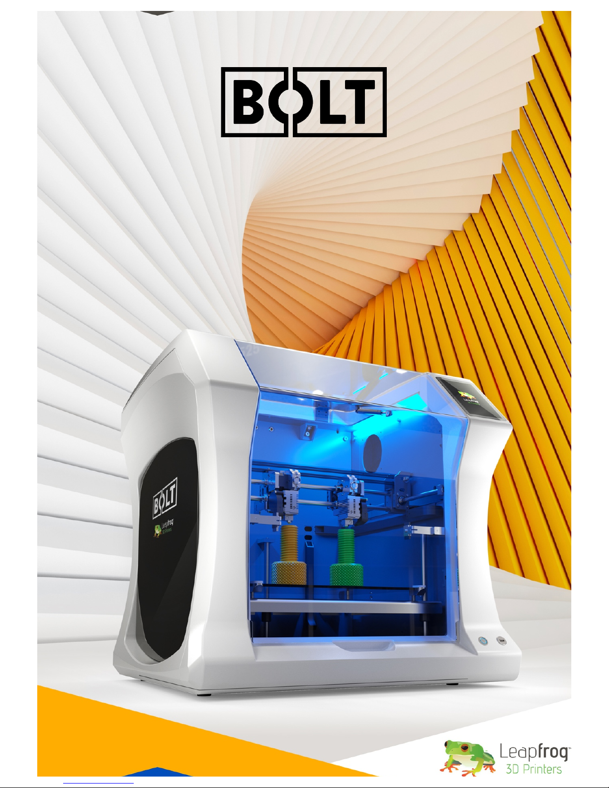
1.3 WHAT IS IN THE BOX
Bolt 3D Printer
Power cable
USB stick
Bed adherence
Safety guide
Creatr Software Voucher
Page 8
8
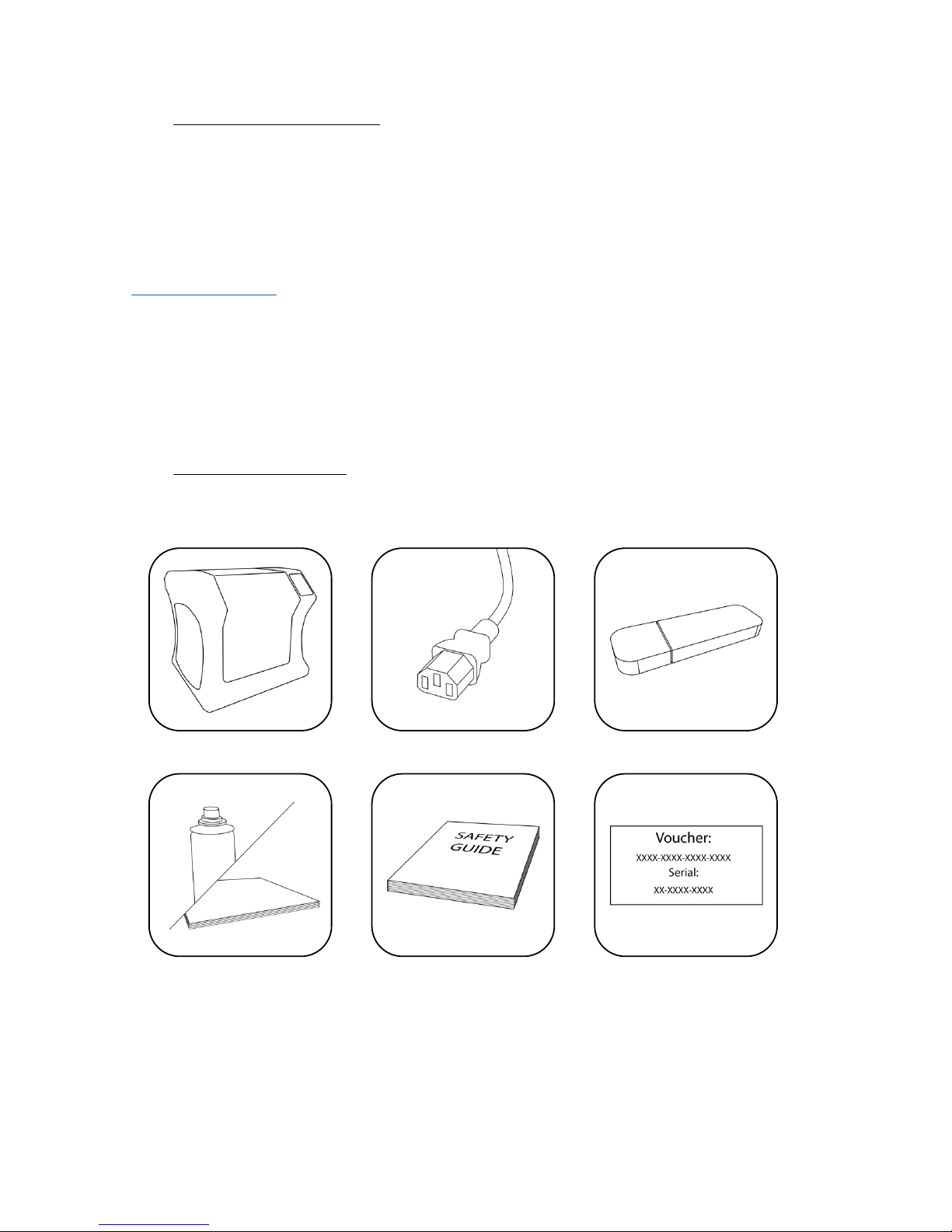
1.4 UNBOXING THE PRINTER
It is important to carefully unbox the printer according to the instructions in order not
to damage the printer. Never try to lift the printer by pulling it up on the print heads, X
or Y axis assemblies, or the print bed itself as this can throw off calibrations or possibly
even break part of the printer.
Place the box with the Box on the
ground.
3 screws can be found at the base of the
crate. Remove a total of 6 screws on the
front and the back of the crate.
Lift the top of the box upwards with two
persons.
Remove the box containing the power
cable and other accessories.
Page 9
9
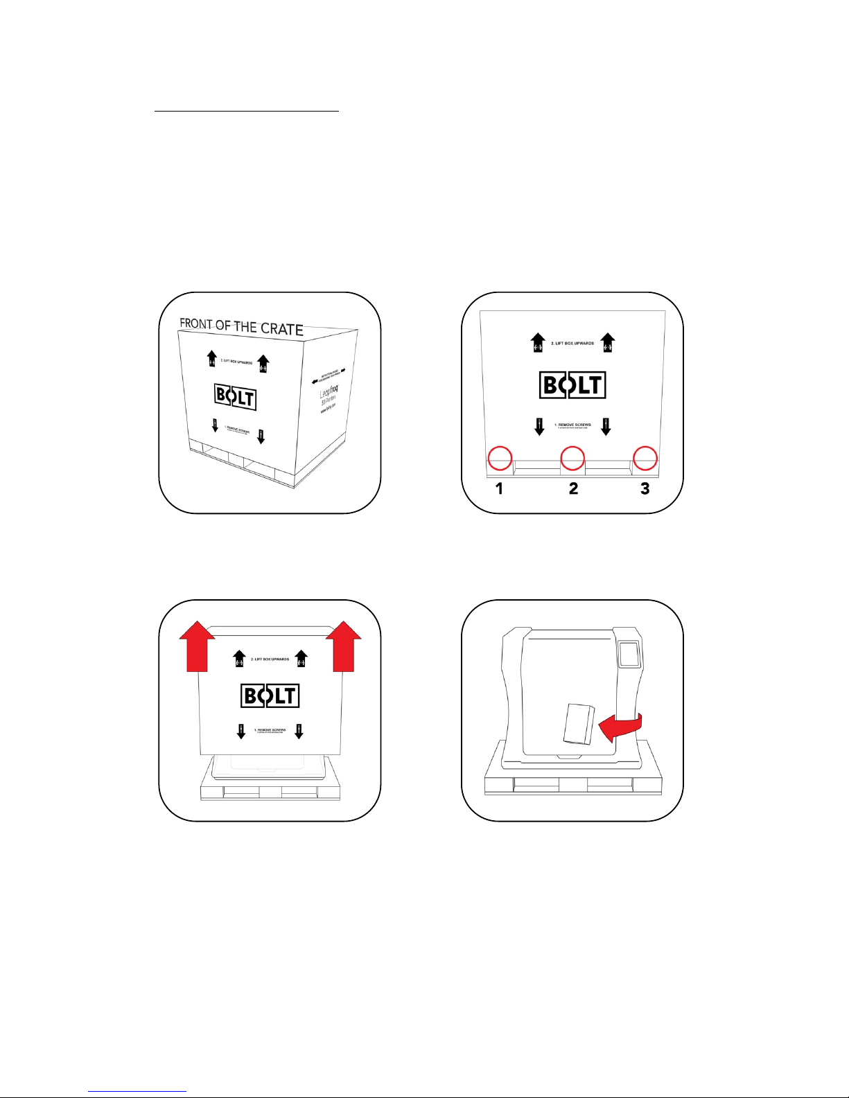
Remove the cover protection on the
outside of the Bolt.
Place the Bolt securely on a table of
workbench.
Open the door and remove the piece of
foam between the Bolt and the door.
On the inside of the Bolt, cut the tie-
wrap found on the right side of the Print
heads.
Page 10
10
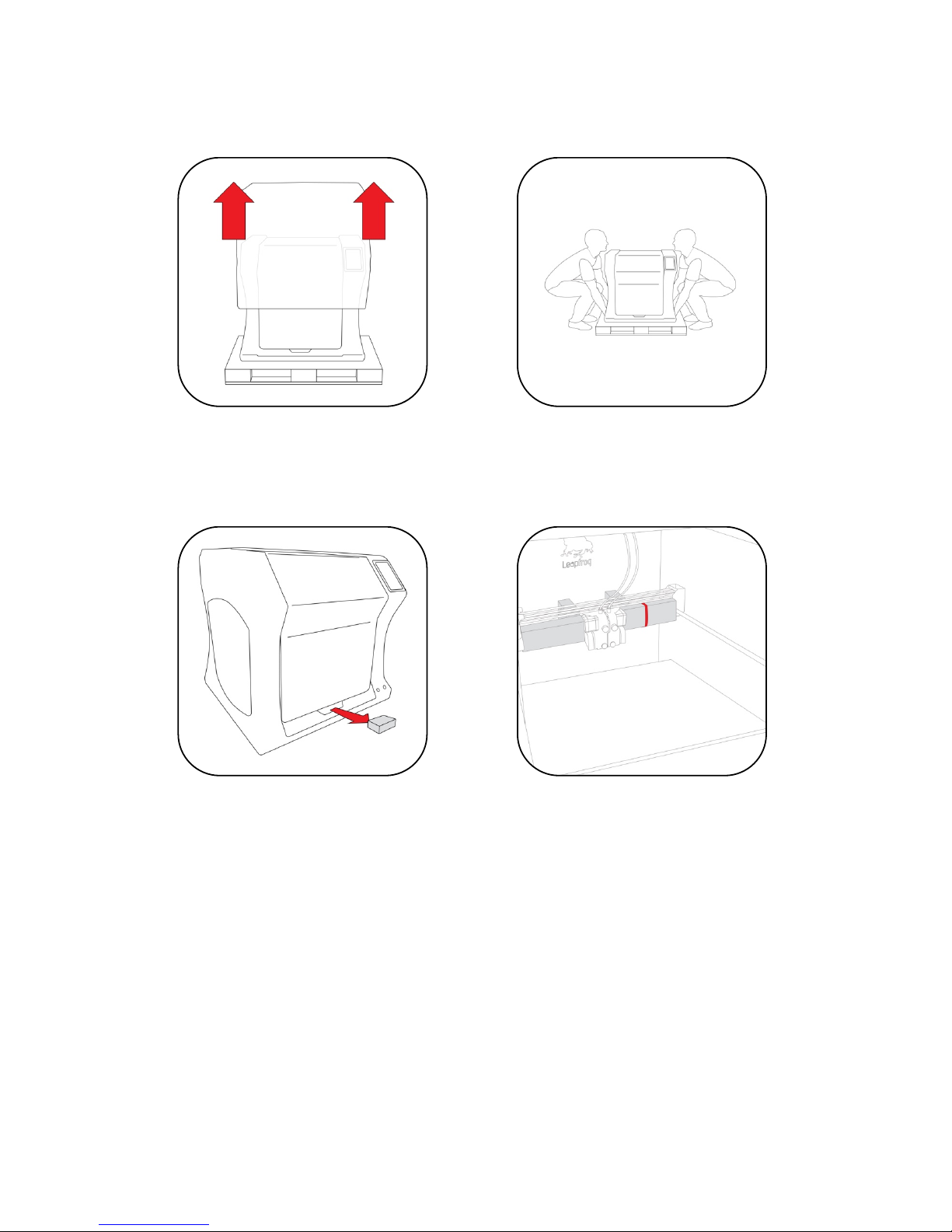
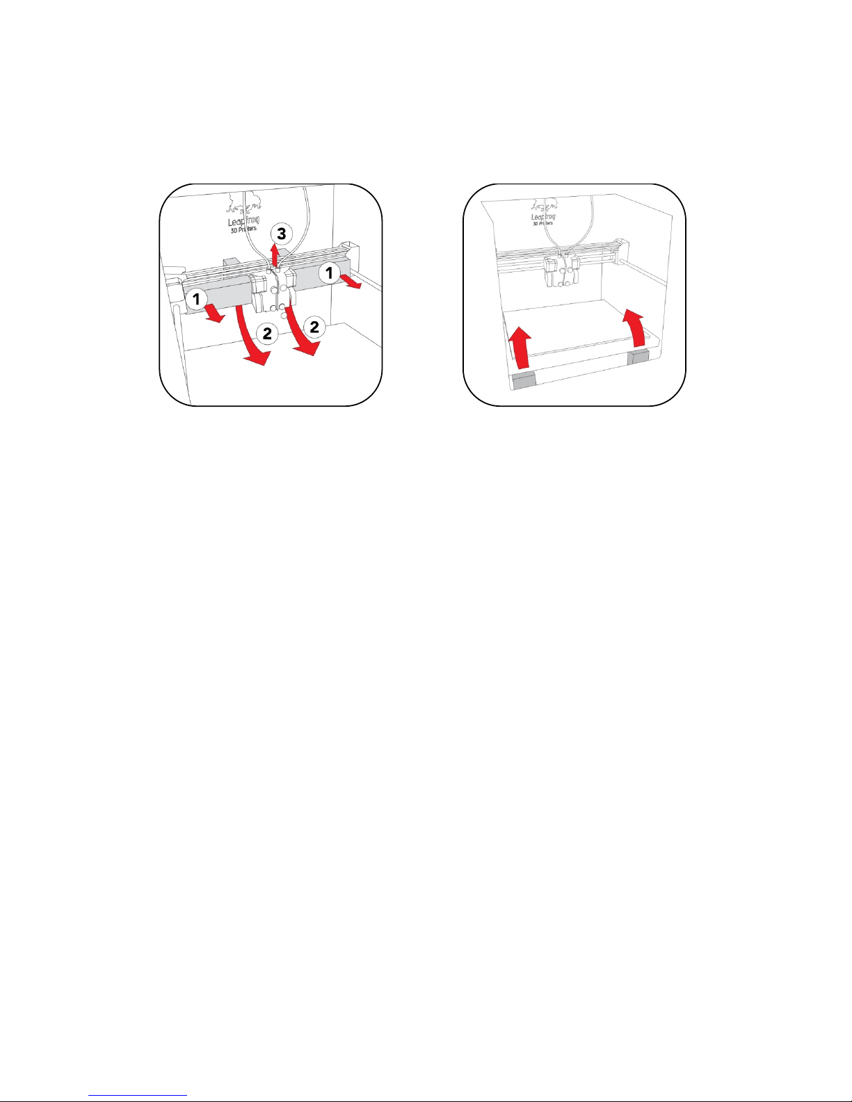
Remove the 4 pieces of foam holding
the print heads in it is place. And
remove the piece of protection between
the two print heads.
Remove the two pieces of foam
underneath the front of the bed.
Get the power cable and plug this in the
back of the printer and plug the other
end in a grounded (!) wall outlet.
Remove any remaining foil, protecting
the exterior of the Bolt.
Page 11

11
1.5 ELECTRIC POWER CORD COMPATIBILITY
Please check the power cord that came with the printer to see if the plug matches the
electrical wall outlet that your country typically uses. The Bolt has a power supply unit
that is switched-mode capable – meaning it will automatically switch between allowed
voltage input between 100 volts and 230 volts. However, make sure that the correct
power chord has been supplied along with your printer.
If this is not the case, please go to our website and open a support ticket, attaching a
copy of the printer’s original purchasing invoice and a photo of the power cable that
came with the printer; our Technical Support Team will place an order for the correct
power cable as soon as possible.
Once you have confirmed that you have the correct power cord, please connect the
power cord to the back of the Bolt in the appropriate slot and plug the other end into
a grounded (!) wall outlet. Failing to make sure that you have a grounded wall outlet
can result in the printer possibly being damaged by an electric power surge. In addition
to using a grounded power outlet, it is also recommended to use a surge protector.
At this point, you can safely turn on the power switch on the back of your printer.
Page 12
12
2 ABOUT THE BOLT
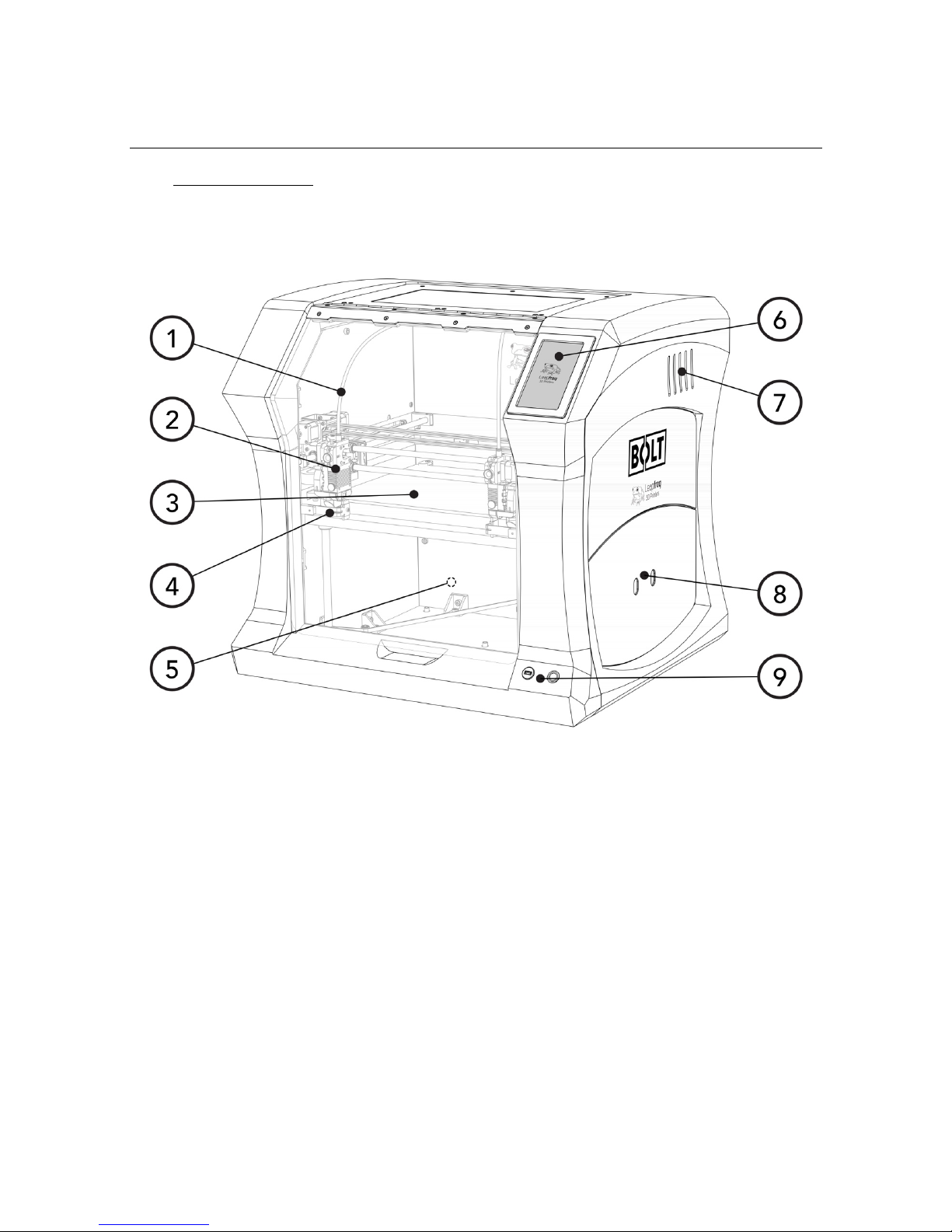
2.1 BOLT OVERVIEW
1. Filament guide tube
2. Print head (one of two)
3. Print bed
4. Nozzle wiper (one of two)
5. Power switch (on the back of the Bolt)
6. Touchscreen
7. Activated HEPA Carbon filter vent
8. Filament compartment
9. On/off button and USB port
Page 13
13
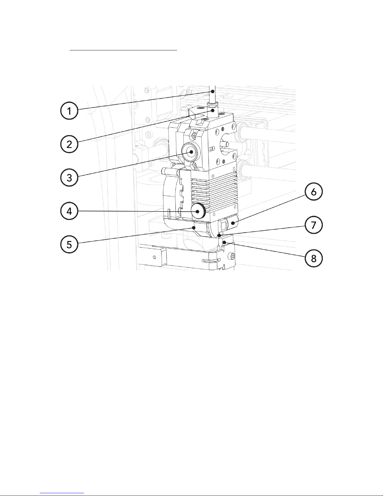
2.2 BOLT PRINTER HEAD OVERVIEW
1. Filament guide tube
2. Push-in coupling
3. Filament pinch wheel (used to control the grip on loaded filament)
4. Hot-end thumb screw (used to swap hot-ends tool-less)
5. Fan-duct
6. Hot-end (includes also nozzle)
7. Nozzle
8. Nozzle wipe
Page 14
14
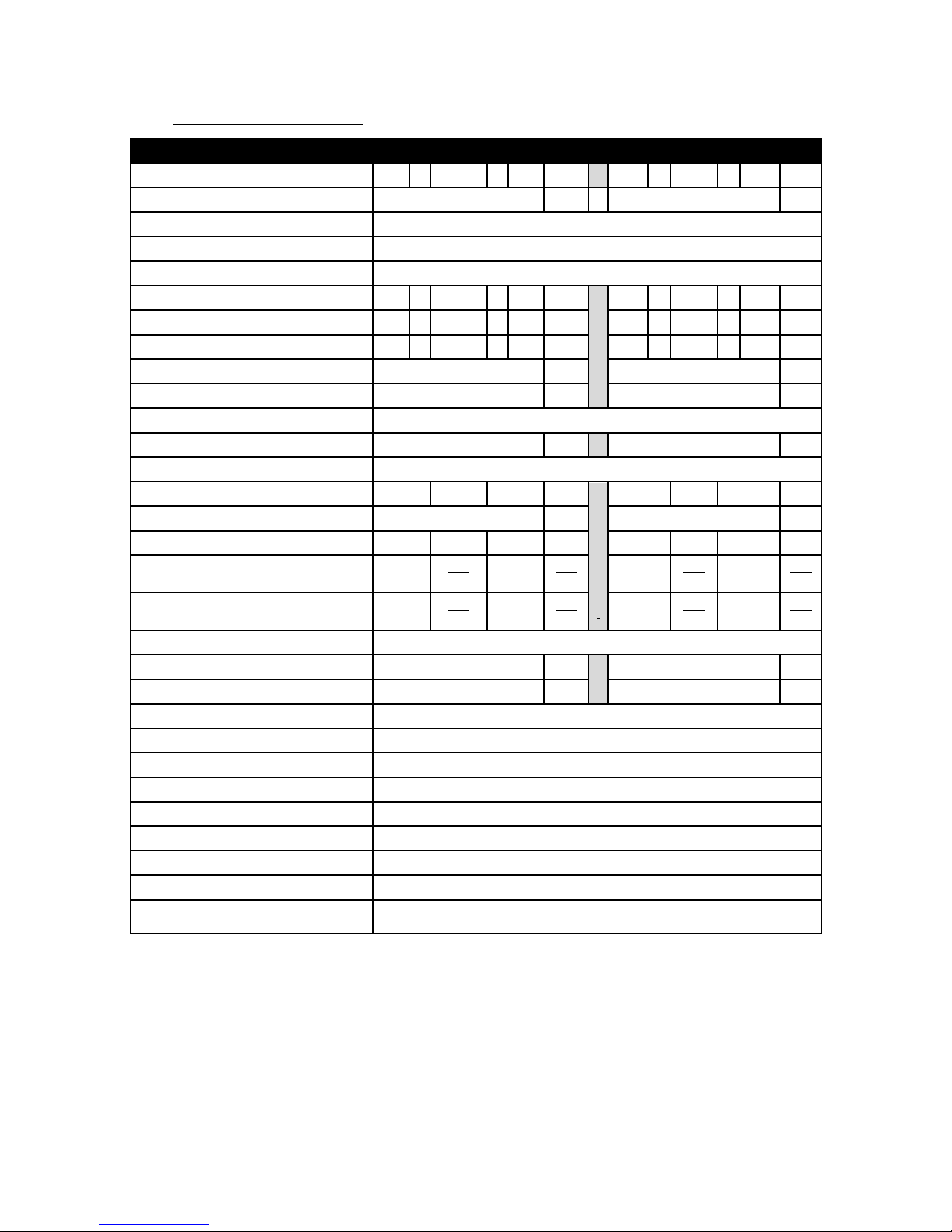
2.3 BOLT SPECIFICATIONS
Specification+
Metric+
++
Imperial+
Physical+dimensions+(DWH)+
723+x+831+
x+
801+
mm+++28.5+x+32.7+x+31.5+
inch+
Printer+weight+
61+
kg+
++
134+
lbs+
Input+voltage+range+
88-264VAC+
Input+frequency+
47+-+63+Hz+
Power+consumption+
600W+
Build+size+single+extruder+(DWH)+
320+x+330+
x+
205+
mm+++12.6+x+13.0+x+8.1+
inch+
Build+size+dual+extruder+(DWH)+
320+x+300+
x+
205+
mm+++12.6+x+11.8+x+8.1+
inch+
Build+size+replicator/mirror+mode+(DWH)+
320+x+164+
x+
205+
mm+++12.6+x+6.5+x+8.1+
inch+
Build+volume+
21.6+
L+
++
4.8+
gall.+
Heated+bed+max+temp+
90+
°C+
++
194+
°F+
Closed+chamber+
Yes+
Hot+end+Max+temp*+
360+
°C+
++
680+
°F+
Number+of+extruders+
2+
Extruder+size(s)+
0.35+++++
mm+++1.38E-02+++++
inch+
Filament+size+
1.75+
mm+++6.89E-02+
inch+
Layer+thickness+
0.05+
to+
0.35+
mm+++1.97E-03+
to+
1.38E-02+
inch+
Advised+printing+speed+(DW)+
6000+
mm+
min+
100+
mm+
s+
++
236+
inch+
min+
4+
inch+
s+
Max.+travel+speed+(DW)+
15000+
mm+
min+
250+
mm+
s+
++
591+
inch+
min+
10+
inch+
s+
Stepper+motors+
1.8°+Step+angle+with+1/32+micro+stepping+
Positioning+accuracy+(DW)+
0.008+
mm+++3.15E-04+
inch+
Positioning+accuracy+(H)+
0.010+
mm+++3.94E-04+
inch+
Body/frame+construction+
Aluminium+Framework+
Heated+bed+construction+
High+grade+glass+
Semi-automatic+print+bed+Z-levelling+
Yes+
Ethernet+connection+
Yes+
Wifi+connection+
Yes+
Internal+OS+
Linux+
USB+standalone+format+
.Gcode+format+
Printing+modes+
Single,+Dual+Material,+Replicator+mode,+Mirror+mode+
Open+ system+ print+ materials+ (*+
experimental)+
PLA,+ABS,+HIPS,+Flex,+Nylon,+Hybrid,+Woodfill,+PVA*,+Carbon*,+other*+
DWH:%Depth,%Width,%Height.%Coordinate%system%reference%Y,%X,%Z%
A%Low-temp%(max%250%degrees)%and%High-temp%hotend%(m a x%3 60 %degrees)%is%supplied%
Page 15
15
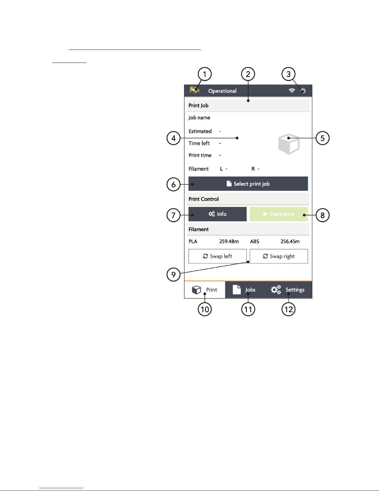
2.4 LEAPFROG USER INTERFACE OVERVIEW
PRINT TAB
1. Software refresh
2. Notifications area
3. Power power options
4. Shows information about
the selected print job.
5. Shows a preview of the
selected print job
6. Navigate to the Jobs tab to
select a print job
7. Shows the temperatures of
the nozzles and bed and
gives access to the built-in
webcam live view
8. Start a print job and select
the print mode
9. Loads the wizard to load or
unload filament for the left
and right extruder
10. Shows the current Print tab
11. Navigate to the Jobs tab
12. Navigate to the Settings tab
Page 16

16
JOBS TAB
13. Software refresh
14. Notifications area
15. Power power options
16. Local and USB storage
17. Search storage
18. Sort storage
19. Filename
20. Print selected file
21. Show information on file
22. Additional information on
file.
23. Delete or copy file to USB
or local storage
24. Shows that the file is not yet
printed
25. Shows that the file is
successfully printed
26. Shows that the file wasn’t
successfully printed
27. Navigate to the Print tab
28. Shows the current Jobs tab
29. Navigate to the Settings tab
Page 17

17
SETTINGS TAB
1. Software refresh
2. Notifications area
3. Power power options
4. General printer information
5. Navigate to maintenance
menu
6. Add, edit or remove
materials
7. Access built-in camera and
set/download created
timelapses
8. Add, edit or remove user
9. Connect to wireless
network and check IP
address.
10. Update the Bolt software
and firmware
11. Navigate to the Print tab
12. Navigate to the Jobs tab
13. Shows the current tab
Page 18

18
SETTINGS TAB
1. Moves both print heads to
the front of the Bolt for
head maintenance
2. Moves both prints heads to
the back of the printer for
bed maintenance
3. Change the amount of
filament on the loaded
spools
4. Calibrate both extruders in
reference to each other
5. Calibrate the print bed in
reference to the nozzles
6. Purge left/right extruder
7. Close maintenance menu
Page 19

19
3 PRINTER SETUP
Before you can start using the Bolt, some preparation is required. Also, be sure to read
Chapter 1.5: Electric Power Cord Compatibility.
The following chapters should be followed to make the Bolt operational and print
ready.
3.1 Setting up user accounts
3.2 Connecting the Bolt to the internet
3.3 Update the Bolt
3.4 Calibrate print bed
3.5 Load filament
3.6 Add materials (if necessary for 3.6)
3.7 Apply bed adhesive
You will be setting up admin and user accounts in order to control the amount of
privileges every user has on the Bolt
Connecting the to the internet and Wi-Fi is also highly recommended and fully use its
auto-updates and connectivity with your mobile phone and/or computer.
Calibrating the bed should be done at least once after transporting the Bolt. The wipers
will need to be check as well.
And finally filament should be loaded and the print bed should be prepared before
each print.
Page 20

20
3.1 SETTING UP ADMIN AND USER ACCOUNTS
As our 3D printers are being used in shared office environments, Leapfrog 3D Printers
has designed the Bolt Software to have User accounts. Remote control will only be
accessible to users with an account and those that do have access may be limited to
what they can do based on their account settings.
Setting up an Admin account is highly recommended before providing the Bolt’s IP
address to the users in your office environment.
NOTE Replacing a forgotten password for an Admin account will be very difficult to
do, so please write it down in a location that you will be able to recover it if need be
later on.
To add a user, select the Settings tab and tap on the
Users menu option. Add a admin user and be sure
to set the check-box on green, next to Admin.
In the picture you see that user admin has
administrative privileges and ‘john’ is an active user.
To the right you see a pencil icon for editing this
user account, a key for locking the account, and a trash can for deleting the user
account.
NORMAL USERS These users can only upload files but cannot start prints from a remote
device.
ACTIVE USERS These users can upload and print, but cannot change settings from a
remote device.
ADMIN USERS Admin users can also upload and print as well as change settings on the
printer from a remote device.
Page 21

21
To add a user, click the Add user button.
Use the touchscreen keyboard (by typing inside each
text field) to fill out the Username, Password, and
Repeat Password fields.
Make sure to indicate whether they will have
administrative privileges or not but switching the
slider on green or red.
Confirm to create the account, and Abort will cancel
the account creation.
3.2 CONNECTING THE BOLT
The Bolt can access the internet and your network by Ethernet or Wi-Fi.
To do so, you will need an internet service in your home/office that is set up on a router.
For a wired connection, simply connect the Bolt with your router using an Ethernet
cable.
For wireless you will also need to know the name and
password of the wireless network being transmitted
by that router so that your Bolt will be able to connect
to the correct network.
Once you have this information, go to Settings tab and
select the Wireless menu option. Your printer should
automatically scan for any wireless networks, but if the
network is not listed, select the Rescan button to have
it refresh the network list.
To connect, simply select the listed network that you
wish to connect to, type in the password and tab the
Connect button.
Once connected, you’ll see the network name, that it is communicating, the signal
strength and that it is locked by the Admin.
If you are currently connected to a network and wish to change networks, you will need
to first disconnect from the current one by selecting the Disconnect button.
Page 22

22
3.3 AUTOMATIC UPDATE FUNCTION
Because our Research & Design department is constantly trying to improve the quality
experience that our customers have with our 3D printers, they periodically provide new
updates that further improve the printer-user experience. For your convenience, these
updates are made available online and can be directly installed on the Bolt, with
minimal printer down-time.
To update your Bolt, go to Settings and press Update to Update to the latest version
available. Please ensure that you are connected to the internet to use this function.
3.4 CALIBRATE PRINT BED
The Bolt is a sensitive machine that moves and
extrudes on the micro-meter level, and exposure to
shipping and transportation can possibly cause the
bed level to lose calibration.
If the first layers don’t adhere to the printer bed, the
whole part can move while printing, resulting in a bad
print. The right distance between the bed and nozzle
prevents this from happening.
To level and calibrate the bed, go to Settings à
Maintenance à Calibrate bed.
Continue Calibration and the screen will show a top
view of the print bed with 4 squares in each corner and
a fifth one in the middle of the print bed. Each of these
squares represent a position on the print bed used for
calibration.
The recommended distance between bed and nozzle is around
0.15 mm or roughly the height of a sheet of paper.
Choose a corner position on the screen and find the knob
underneath the bed at the corresponding position. Turn this
knob clock-wise to raise the bed, and counter clock-wise to lower
the bed.
Page 23

23
Hold a piece of paper between the nozzle and print
bed and raise the bed until the paper is slightly
pinched between the bed and nozzle. Repeat this until
all four corner nozzles have the same distance from
the bed, checking the middle calibration position last.
3.5 LOADING/UNLOADING FILAMENT
Filament is the material what the Bolt uses to print. The
extruder on the right side is treated as the
default/main extruder. Our Creatr Software (powered
by Materialise) is also is set up that way.
We recommend Leapfrog MAXX filaments and preferably PLA for the initial loading
process and prints.
Filament will be loaded in the right side of the Bolt and guided via tubes to the
designated print head. The filament will be melted in the print head and printed to the
print bed.
In the following steps we will swap the Right filament. Swapping the Left filament will
follow the same process.
NOTE The print head assembly will perform some forceful movements during this
process. Please keep all body parts or objects clear when this movement occurs to
prevent injury or damage of the machine.
Page 24

24
NEEDED STEPS TO LOAD FILAMENT
1. Remove the filament guide tube from the coupling
2. Select Swap Left/Right in the print tab
3. Unload the current filament if necessary
4. Select the correct filament and set the estimated amount left on the spool
5. Feed the filament up to the drive gear
6. Feed the filament into the drive gear
7. ‘Load filament’ or ‘Load extra filament’ until the filament is gripped in the drive
gear
8. Re-connect the filament guide tube to the coupling if necessary
Page 25

25
STEP 1
Locate the orange push-in coupling on the right print
head, connecting the print head to the filament guide
tube. Remove the tube from the print head by pushing
the orange coupling down and pulling tube upwards
in the opposite direction. Let the tube disconnected
until the filament is loaded correctly.
NOTE Loading filament can also be done without
disconnecting the push-in coupling, but it is strongly
advised to use this method in order to ensure success
loading filament and know what is happening.
STEP 2
On the Bolt Software, select the
Print tab and choose the Swap Right
option for the right extruder.
It will ask you to confirm the unload
process; please do so.
NOTE The printer will first pre-heat the selected nozzle to help load and unload
filament. This is will extend the life of your nozzle blocks and will help prevent clogs.
STEP 3
You’ll then be prompted to physically unload and roll of the filament spool that was
previously loaded in the printer, if applicable. To do this, open de filament
compartment on the right side of the Bolt and remove the filament spool from the
filament compartment. The right extruder will then be empty and available to load the
replacement roll of filament.
Page 26

26
STEP 4
After unloading the previous roll of
filament (if applicable), the software will
ask which type of filament is loaded into
the extruder that you just unloaded.
Select the right material from the drop
menu. If the correct material isn’t listed,
select abort and add an additional
material. This can be done in the in the
Settings tab under Materials, as is
explained in the next chapter.
Select how much filament is on the spool.
This way, the Bolt knows whether or not
there will be sufficient filament to print the
selected print job and will notify you when
there will not be enough. Keep in mind
that this is as accurate as the user can
determine the amount of filament left on
the spool, so it will be an estimate.
STEP 5
Get the filament that needs to be loaded and un-package a roll of filament from the box
if needed.
NOTE Some filaments (like PVA and Nylon) have special properties that make them
susceptible to things like air moisture or sunlight. Please take extra care of these types
of filaments, making sure not to leave them in the printer or outside of their protective
packaging. PVA in particular should always be unloaded from the printer immediately
after use to help prevent clogging of the nozzle.
In order to help the filament feed through the machine, clip the end of the filament to
where it forms a point and then use your fingers to straighten the filament out. Being
wound around spool, the filament has a natural bend; straightening just the first few
centimetres out helps to prevent the filament from catching when it reaches a filament
tube coupling.
Page 27

27
Begin feeding the filament through the correct filament tube port
on the right side of the printer. For loading filament into the right
extruder, the right filament compartment must be used, for the
Left extruder, the left.
When feeding the filament to
the filament entry port, ensure
that the filament is rolled of
correctly of the filament spool. The filament should be
rolled from the bottom of the spool into the entry port.
If the filament is loaded incorrectly, then the loaded
filament can get damaged while printing and clog the
nozzles.
STEP 6
Feed the filament through the filament entry port;
keep feeding until you see the filament in the
translucent filament guiding tube reach all the way
print head filament drive gear. Make sure to that the
filament is fed past the end of the tube.
If you need help feeding the filament to the drive gear,
feel free to disconnect the translucent filament guiding
tube from the top of the print head and feed the
filament through the top down into the print head.
STEP 7
When the extruder is preheated, you will be prompted to confirm that you are ready to
load the filament. Press the Load button and the print head will begin feeding filament.
While the drive gear in the print head will start turning in order to feed filament, keep
feeding filament by hand and apply a little pressure in order for the drive gear to grip
the filament. Repeat this until the filament is gripped by the drive gear.
STEP 8
The filament will be correctly loaded if the nozzle extrudes filament by simply pressing
‘load more filament’ on the software. Re-connect the tube if necessary by pushing the
tube back in the pushing coupling.
Page 28

28
3.6 ADD MATERIAL
Materials in the Bolt software are used to pre-heat and
prepare the Bolt for loading and unloading filament.
The actual materials settings are set in the G-code of
the print file. Settings of changing temperatures for
print settings is done in the Creatr Software.
When a material isn’t available when loading filament,
it can be manually added. To see what materials are
available or to add an additional filament, go to the
Materials under the Settings tab.
A list of materials is visible under Materials and adding
a material can be done with +Add profile.
When adding a material, fill in a profile name and add
the correct temperatures to complete the material
profile. Press save the to keep, and start using the
profiles.
3.7 ADHESIVE MATERIAL
Many filament types require an adhesive material to be applied
to print bed in order to help the printed part to stick and hold to
the bed. Without it, most 3D printed parts would stick to the print
head and move around after the first few layers. Therefore, we
recommend almost always applying some sort of adhesive
material such as our print stickers or 3D Spray from Leapfrog
MAXX Essentials (for European countries only).
NOTE Failing to ensure that a print is sticking to the bed for at
least the first few layers could result in a large mass of filament
collecting on the tip of the nozzle and can severely damage the
printer. Though we don’t expect the print to be monitored from
beginning to end, we strongly advise to monitor the first critical layers of the print. Using
the built-in webcam enables the user to monitor the printing process remotely.
Page 29

29
4 PRINTING
The Bolt is capable of storing and 3D printing G-codes generated with Creatr powered
by Materialise.
The following will be covered in the next chapter
4.1 Starting Print jobs
4.2 Finishing Print jobs
4.3 Using different printing modes. Sync mode and Mirror mode
4.4 Information available on print jobs
4.5 Accessing and storing print jobs
4.1 STARTING PRINT JOBS
To make a 3D print, 3 things are required. Filament, a 3D file in G-code format and a
3D Printer. Creating a G-code from a STL is explained in the next chapter. To start your
first print, you can use the pre-installed file on the storage of the Bolt. Choose PLA as
filament for the Bolt example print.
NOTE When starting a print, it is strongly advised for the user to know that the filament
is loaded correctly, the bed is correctly calibrated and the print bed is supplied with
adhering material like 3D Spray or a print sticker. This is explained in the previous
chapter.
The following steps will be explained below.
1. Start-up the Bolt
2. Prepare the print bed
3. Select the print job
4. Select ‘Start print’.
5. Wait until the Bolt is heated up and starts printing its first layers.
STEP 1
Start up the Bolt and load filament in the Bolt as explained in the previous chapter.
Navigate on the Bolt software to the Print tab.
STEP 2
Prepare the print bed with necessary adhesive. This is explained in chapter 3.7.
Page 30

30
STEP 3
Press ‘Select print job’ to navigate to the internal storage of the Bolt. Here all prints on
the Bolt are located, as well as the linked USB storage device. Select the file you want
to print and navigate to the Print tab by pressing the ‘play’ button or ‘Print’ in the bottom
of the screen.
NOTE Trying to run a G-code file that was not designed for the Bolt and filament type
that you have loaded will result in a failed print, most likely a clogged extruder and can
damage the hardware of the Bolt. Ensure that you have used the latest and correct
settings in the Creatr Software from Leapfrog 3D Printers.
STEP 4
Press ‘Start print’, select the desired ‘printing mode’ (for the first sample print, we advise
‘normal’) and press Start Print.
STEP 5
The Bolt will start heating its extruders to the correct temperature. Afterwards it will
begin moving its head and start extruding filament on to the bed. The first couple of
layers is critical for a successful print.
For more advanced users; during the first layers, the bed height can still be adjusted
using the knobs underneath the bed.
NOTE If for any reason the result has holes, split layers, or failed, please contact
Leapfrog Technical Support via our ticketing system on support.lpfrg.com; please
upload a photo of the result along with a digital copy of your original purchasing invoice
so that we can provide you with a solution as fast as possible.
Page 31

31
4.2 FINISHING PRINT JOBS
After the needed amount of time, the Bolt will finish its Print job and will let the user
know that the Print job is finished.
The following steps can be followed to successfully remove the print and prepare the
Bolt for future print jobs.
1. Check if the print is done printing
2. Remove the print from the print bed
3. Clean the print bed.
STEP 1
A notification on the top of the Bolt software telling the user that de Print is finished.
Pressing the notification will remove it from the screen and the print can ben removed
from the Print bed. The notification will also be visible on another device if the user was
still logged into the printer.
STEP 2
Carefully remove the print from the print bed. The print might still be strongly adhered
to the print bed so apply gradually apply force if necessary. Applying, or spraying
regular water to the bed can help loosen the print from its bed. Waiting a couple of
minutes will let the water dissolve the 3D Spray, releasing the print from the print bed.
STEP 3
Clean the print bed of any debris and left over filament sticking to the print bed. A putty
knife or similar tool can be used. Take care when using a tool when cleaning a debris
from a print sticker, as it can damage the sticker. Window cleaner can be used to clean
the residue of 3D Spray.
Page 32

32
4.3 USING DIFFERENT PRINTING MODES
The Bolt is fitted with two separate heads which provides for new ways of printing. The
two heads can work at the same print job, extruding a single or dual material print, or
work simultaneously, both printing at the same time.
NOTE When the selected print is not yet fully
analysed, a Force print button will appear.
This will allow the user to print the print. Be
sure that the selected print is within the
bounds of the printing area.
NORMAL PRINTING MODE
Pro:
Dual material/Dual colour
Full bed range, larger objects
Con:
Normal production speed
In Normal printing mode, the Bolt can print single extrusion or dual extrusion prints and
the full print bed can be used in Normal printing mode.
Creating a single or dual extrusion print is set in the G-code and is done when creating
a G-code file.
Printing a single extruder print will need only the Right, or Left filament loaded. When
printing a dual extrusion print, both Right and Left filaments will have to be loaded.
SYNC MODE PRINTING
Pro:
Double production speed
Make a copy of the print
Used for multiples of 1 print
Con:
Single material/Dual colour
Page 33

33
Sync mode printing will use both print heads simultaneously for one single extruder
print, printed twice. The result is a copy of the selected G-code over the duration of one
print job. This means that printing with both heads simultaneously the Bolt prints twice
as fast!
In Sync mode, the print bed will be halved since the Bolt will have to print the same
object twice. Both extruders will be used so both the Left and Right filament should be
loaded.
Printing in sync mode will require a G-code file set on the correct (right) half of the print
bed. The Bolt will copy the G-code automatically to the other half of the print bed.
MIRROR MODE PRINTING
Pro:
Double production speed
Make a mirror copy of the print
Used for symmetrical prints
Con:
Single material/Dual colour
Printing a file in mirror mode will also use both print head simultaneously for on single
extruder print, printed twice. The difference with Sync mode printing is that the print
will be not be copied, but mirrored over the Z-axis. This can be useful when making
moulds or orb shaped objects.
In Mirror mode, the print bed will be halved since the Bolt will have to print an additional
mirrored copy of the selected print. Both extruders will be used so both the Left and
Right filament should be loaded.
Printing in sync mode will require a G-code file set on the correct (right) half of the print
bed. The Bolt will copy and mirror the G-code automatically to the other half of the print
bed.
4.4 INFORMATION AVAILABLE ON PRINT JOBS
The Bolt analyses any print job uploaded on the local storage of the Bolt. This
information will help you prepare you amount of filament en time, creating more insight
on the selected print job.
The Bolt will let the user know which nozzle is set in the G-code, as well as how much
filament will be needed. If the amount of filament left on the loaded filament spool is
less than needed, then the Bolt will disable the start print function, preventing the user
to start printing an incomplete print.
Page 34

34
It will also give you a rough preview of the selected print job as well as an estimation on
how much time it will take printing it.
4.5 ACCESSING AND UPLOADING PRINT JOBS
The Bolt is fitted with 32 GB which can be used for storage of G-codes for the Bolt. This
storage can be accessed on the Bolt or on your computer, phone or tablet using Wi-Fi.
The Bolt has a USB port as well.
Accessing the Storage can be done via the Jobs tab in the bottom of the screen. Here
you can access the local storage, USB storage and search for a print.
When plugging in a USB storage device, you will be prompted to browse the USB files.
You can also access the USB on the top of the Jobs tab. On the USB storage you can
navigate to the desired file and upload it to the Bolt.
Any file on the Bolt storage will be analysed. The Bolt will read the G-code for
information like which nozzle is used, how much filament will be needed and will
provide the user with a rough preview.
To upload prints to the Bolt using Wi-Fi, the Bolt has to be connected to the same
network as your computer. In the wireless menu, an IP address can be found. Place this
IP address into your browser as you would a website URL to access the Leapfrog User
Interface of the Bolt. Login to get the right privileges and upload files in the Jobs tab.
For more information on accessing the Bolt via your network, see to chapter 6.3.
Page 35

5 CREATING A PRINTFILE
The Bolt reads G-code. A G-code is a common used file type for production machines
and setting the right parameters for the Bolt is essential. The use of a different type of
settings of another machine can damage or crash the Bolt.
To create a G-code for the Bolt, a 3D model will be needed and imported in the Creatr
Software. A common used file type for digital 3D models is STL and this will be used to
import the 3D model into the Creatr Software.
NOTE Creating a 3D model is not explained in this tutorial. Free 3D model STL’s can
be found online, as well as free 3D modelling tools.
Creating a G-code from a STL means that the Creatr Software will slice the STL in
separate layer, in order for the Bolt to build the 3D model layer per layer. Another
commonly used word for a program like this is therefor a ‘slicer’. For more information
on 3D printing and slicing, go to courses.lpfrg.com and follow the free introduction
course.
Page 36

36
5.1 CREATR POWERED BY MATERIALISE
Install the Creatr Software on a computer which meets the minimum requirements and
create or download the desired STL file that you want to print. For more information on
the Creatr Software refer to the Creatr Software User Manual:
http://cloud.lpfrg.com/materialise/manuals/CREATR.pdf
And download the Creatr Software here:
http://www.lpfrg.com/materialise/download
NOTE Make sure you are using the latest version and profiles of the Creatr Software
for best results.
5.2 PRINTER SELECTION
Once Creatr Software opens, select the Bolt
from the Printer Selection tab at the top of
the program.
5.3 IMPORT
Click the Import tab button at the top. You’ll
be prompted to browse for the STL file that
you would like to print. Find the file’s
location, select the file, and click Open.
Your STL model will be imported to the build platform according how you have your
settings in the Options menu.
Page 37

5.4 TRANSFORM
Upon importing, the Transform tab will
automatically be selected. In the transform
tab you can adjust the imported model
using various options;
Move – This will let you move the selected object on the print bed.
Rotate – This will let you rotate the selected object.
Lay-flat – This will lay the selected plane of the object flat on the print bed.
Rescale – This can make the selected object bigger of smaller.
Duplicate – This allows you the duplicate the selected object multiple times.
Arrange the model keeping in mind in what printing mode the model will be printed.
In Normal printing mode, the print can be placed anywhere on the print bed.
SYNC AND MIRROR PRINTING MODE The print has to be placed on the Left half of the
print bed. The other half will be generated by the Bolt.
5.5 SELECT NOZZLE
Select the desired nozzle for the G-code. By default, the Right nozzle will be selected.
To switch nozzle, or allocate the desired nozzle to the desired part, toggle the Right and
Left indicator on the part information on the right top of the screen.
When using Sync or Mirror mode, the
single nozzle selection will be by-passed
and the nozzle selection won’t be used.
When printing dual material, the correct
filament needs to be loaded to the correct nozzle.
Page 38

38
5.6 PRINT
Select the Print tab. Creatr Software
has Categories of Profiles that need
to be set; one of them (Machine
Settings) is set automatically in the
Edit Profiles window. However, there
are variations of the other 4 types of
profiles, so you’ll need to select which of the variations you want to use under the Print
tab:
Material Profile – this profile
contains settings for the filament
material type that you plan to print
with.
Print mode – this determines what
Slicing Strategy – this profile
contains settings for layer
thickness.
Build Strategy – this profile
contains settings for the outside
contours of the print, the
upskins/downskins (top and
bottom printed layers), the infill,
and more.
Support Strategy – this profile contains settings for any additional printed material such
as a skirt, brim, raft, or generated support structure material.
The Edit profiles button allows you to change the settings of these profiles
NOTE For more detailed and in depth information, refer to the Creatr Software User
manual
http://www.lpfrg.com/materialise/download
Or contact our support: http://support.lpfrg.com/.
Page 39

5.7 PREVIEW AND GENERATE G-CODE
When you’re ready to ‘slice’ the model into a G-code, select the Generate G-CODE
button (found under the same Print tab near the bottom) and click Save. The software
will show a slicing completion percentage.
Note that there is a Cancel button if
you would like to change settings and
re-slice.
For now, we no longer need the
Creatr Software. However, printing
more complex parts often ask the user
to tweak and tune the settings to the shape of the part. This involves testing and
adjusting print settings in order to get the best result possible.
Page 40

40
6 LEAPFROG USER INTERFACE
The Bolt is equipped with software that will give the user control and information on
printing, storage and maintenance of the Bolt. For a quick overview of the Leapfrog
User Interface, see to chapter 2 of this manual. For more information on how to use the
software for printing, see to the chapter ‘Printing’.
6.1 LEAPFROG USER INTERFACE FEATURES
The software provides the user control over the Bolt when printing and keeping the
printer in good condition. In the settings tab the Bolt can be calibrated and set in certain
positions to help the user maintain and clean their Bolt.
The User Interface is accessible via other platforms like a phone, tablet and computer
and can update automatically. When connected to the Bolt with a remote device, the
user can download and upload files, stored on the Bolt. The built-in webcam can be
accessed as well and timelapses can be made and downloaded from the Bolt.
When uploading files, the Bolt will analyse the file to provide useful information as
printing time and needed filament. When the Bolt sees that the amount of filament
exceeds the amount filament left on the spool, it will tell the user.
6.2 REMOTE ACCESS
The Leapfrog User Interface can be controlled using the touchscreen on the machine,
or with another device equipped with network capability and a browser. This also
enables the user to use the webcam’s live view function.
Using the Bolt from the touchscreen will give the user full access to it’s functions and
capabilities. Accessing it remotely will restrict the user with certain functions depending
on the assigned privileges from the account. The different types of users are;
NORMAL USERS These users can only upload files but cannot start prints from a remote
device.
ACTIVE USERS These users can upload and print, but cannot change settings from a
remote device.
ADMIN USERS Admin users can also upload and print as well as change settings on the
printer from a remote device.
Page 41

6.3 CONNECTION THE BOLT USING YOUR NETWORK
Connecting to the Bolt via a remote device can be done using the following steps.
1. Connect the Bolt to your network
2. Find the IP address of your Bolt on your Bolt
3. Connect your device to the same network
4. Open the IP address in your preferred browser
5. Login with your user account
STEP 1
Connect the Bolt to the network using Ethernet or Wi-Fi. When using Ethernet, use a
Ethernet-cable to connect the Bolt directly to the router.
When using Wi-Fi, connect the Bolt to the Wi-Fi network using the Settings à Wireless
tab, as explained in the chapter ‘Printer Setup’.
STEP 2
Go to Settings on the Bolt and go to Wireless. If the Bolt
is connected correctly to the network, there will be a
number shown in the top right corner consisting of 6 to
8 numbers. In this example we will use the IP address
192.168.0.25.
This is the IP address your network as allocated to the
Bolt when it connected to the network and which will be
used to connect the remote device to the Bolt.
STEP 3
Go on your preferred device with network capabilities
and a browser and connect it to the same network as the
Bolt.
STEP 4
Open your preferred internet browser on the remote device and type in the IP address
you have found in the Wireless menu of the Bolt.
The browser should start up the Leapfrog User Interface of the Bolt on your device.
Page 42

42
STEP 5
In order to be able to print or change settings, the remote device should be logged in
to the admin or similar privileged user account.
To log in, click login in the top right corner of the screen and fill in the correct user name
and password.
6.4 USING THE WEBCAM
The Leapfrog User Interface can be used to access the
built-in webcam to view the current print job or create
a time lapse of your print.
There are two places where you can access the
webcam. On the print screen go to info, and click Live
stream to see a live stream of the built-in webcam.
To access the webcam, go to Settings à Webcam, to
open the webcam screen.
Here a current view of the webcam will be shown as a
picture, which can be refreshed. Livestream can also
be selected to view a live stream of the current print
job.
To create a time lapse, the Timelapse settings must be
enabled before starting a print job. Afterwards, the
timelapse can be found under ‘Finished timelapses’ were they can be saved or deleted
from the Bolt.
6.5 PURGE NOZZLES
This function can be used to purge the nozzles of excess or old filament. This can be
useful when cleaning the nozzles and keeping them in good condition.
6.6 MATERIALS
Under Settings àMaterials different types of materials and filament can be added,
edited and removed.
The Bolt pre-heats the nozzles before purging, cleaning and swapping filament.
Different filaments have different nozzle temperatures. Setting the temperature per
Page 43

type of material correctly helps prolong the life or your nozzles and will reduce the
possibility of clogged nozzles greatly.
Page 44

44
7 PRINT SETTINGS
Print settings are very important for successful prints. The print settings are tailored to
the type of material, part, use and quality the user wants.
A part consists of the outside and the inside, or skin and infill. How to print each part of
a total print can be changed, with the speed, amount of skins, amount of retraction and
many more. More information about print settings can be found in the Creatr Software
manual or on courses.lpfrg.com.
7.1 PRINT SPEED VS PRINT QUALITY
As is with regular paper printers, 3D printers also give the user the option to choose
between speed and quality. In general, this means that printing on slower speeds yields
better results in terms of quality and details.
7.2 MATERIAL PROFILES
Material profiles are settings for printing with a specific material. Choosing a profile will
tell the printer how to print the chosen material. This will heavily influence your print
quality and advanced users will adjust the settings per specific print.
7.3 PRINT MODE
Print mode specifies the kind of print your will print. There are 4 different print modes
each with their own use.
Part - Printing a part will print a regular print. This will be the setting most used
Support - This is generally used with dual extrusion. It can be useful to print the part
with one nozzle, and the support with the other like soluble support.
Contour - This will print a single wall shell, or contour, of the selected part in the Creatr
Software.
Infill - This is again generally used with dual extrusion. A part is made of its outside, or
the skin, and the inside, or the infill. The infill can influence the strength or weight of the
part by using more, or less infill.
Page 45

7.4 SLICING STRATEGY
Slicing strategy determines how thick each layer is of the print. Thicker layer will result
in faster print, but courses finishes and lower detail.
7.5 BUILD STRATEGY
The Build strategy determines the amount of up-skin and down-skin (top and bottom
layers) as well as the amount of contours and infill.
7.6 SUPPORT STRATEGY
Support is needed in 3D printing to prevent part of a print from falling down, also
known as overhang. Or is used for complex parts in combination with soluble support,
a material which can be dissolved after printing.
Brim – A brim is a layer, of multiple layer around the print, touching the outside of the
print. This can help stabilise delicate parts printed upwards of the print.
Raft – A raft is a layer underneath the print, which can be broken away, after printing.
This can help stabilise small footprints of the part to create a stronger foundation to
print on.
Standard – With standard, no support will be printed.
Support (same material) – Also known as break-away support. This support will be
printed in the same material and can be easily broken of the part after finished the print
job.
Support (solvable material) – This support can be dissolved after printing, using a
soluble material like Hips of PVA. This can be useful for complex past, where breaking
or removing the support can be hard to reach.
Page 46

46
8 MAINTENANCE & TROUBLE SHOOTING
When using a machine, maintenance has to be done to keep the Bolt in good condition,
of to ensure the Bolt is calibrated correctly. Whenever you encounter a problem, or the
printer isn’t functioning properly, don’t hesitate to contact our support on
support.lpfrg.com.
8.1 INSTALLING UPDATES
The Bolt can update automatically when connected to the internet. Be sure to check
regularly in the Settings tab if an update is available. The number of updates available
is indicated by the number shown in the red circle.
To update, go to Update in the Settings tab, and press refresh in the top right corner.
Then, press update to update the Bolt.
8.2 CLEANING THE PRINT BED
The print bed is normally provided of an adhesive layer, a sticker or 3D Spray, and
debris from the last print.
This Spray and debris can be removed using a detergent like window cleaner and a
putty knife. Scrape the filament debris away with a putty knife and clean the free
platform with a mild detergent. Be careful using a putty knife when removing any debris
from a print sticker as it can easily damage the print sticker.
8.3 CLEANING THE EXTRUDERS
In case of a clogged nozzle, heat up the clogged nozzle as if you were swapping
filament. Try to unload all filament from the extruder. Afterwards, wait until the extruder
is properly heated and re-load filament into the extruder.
8.4 REPLACING THE EXTRUDERS
When a nozzle is not working properly, replacing the hot-end can be a solution. To
replace the hot-end, unscrew the lower thumb screw on the front of the print head.
Disconnect the hot-end at the back of the nozzle block and replace the faulty hot-end
8.5 LEVELLING EXTRUDERS
Perform bed calibration and calibrate the bed on the four corners. Position the print
heads at the center position and get a sheet of paper, of a spacer of 0.150mm. Place
the spacer, or piece of paper, between the bed and nozzles. Unscrew the lower
Page 47

thumbscrews of both heads, loosening both hot-end and dropping them on the spacer.
Tighten both thumbscrews when both extruders are down on the spacer to level the
both extruders.
8.6 CALIBRATE PURGE WIPERS
NOTE The wiper height should be calibrated when the costumer receives their Bolt. If
you think that the wipers aren’t calibrated correctly, continue reading.
Before and after each layer, the Bolt will purge its nozzle
to remove any excess filament to prevent oozing and
leakage of filament on the printed part. The wiper
height should be gently touching the nozzles.
When the wipers are too low or too high, purging won’t
be effective, resulting in strings and oozing your printed
parts which need to be removed afterwards.
To adjust the height of the wipers, you can unscrew the
wiper from its holder. Then the wiper can be adjusted
by either widening the hole in which it is fastened or
cutting the top of the wiper to the correct height.
When the wiper is at the right height, fasten the screw
holding the wiper in place.
Page 48

48
9 CONTACT & ADDITIONAL SUPPORT
9.1 TECHNICAL SUPPORT INFORMATION
Obviously, there is a lot to 3D printing with the Bolt that we couldn’t include in our User
Manual. That doesn’t mean that the information isn’t available. We have already
mentioned that we provide an ever-growing knowledge database that we like to refer
to as ‘Solution Articles.’ If you’ve got a question or technical issue that we didn’t answer
in this manual, please feel free to go to:
http://support.lpfrg.com/support/home and start typing key words related to your
question/issue in the search field on that page. This search field will start generating a
list of articles usually before you’re even finished typing.
If you find that there isn’t an article related to your question/issue, we also have a
ticketing system that, once you set up an account (which is a free, and fast process),
you’ll be able to open new tickets direct to our support agents, who are eagerly
awaiting to assist you. In the ticketing system, up to 15MB of files can be sent per
message allowing Technical Support to send you links, photos, videos, test G-code files,
and more. You too could upload photos and videos of your technical issue to better
describe what is happening. Customers have praised our ticketing system in the past
as being fast, chat-like, and a quick method of resolving any questions or issues that
they had.
We also offer live messaging chat – when agents are available – that can be accessed
by logging into the ticket system.
Questions can also be answered over the phone. We advice you to create ticket
beforehand and have you ticket number nearby. Simply give us a call: +31852080825
between the hours of 7:00AM – 3:30PM CET, Monday through Friday. At the time of
writing this manual, we do not have a toll free phone number.
When leaving a message for a phone appointment, it is advised to have a ticket created
as well.
Page 49

9.2 CREATR SOFTWARE ASSISTANCE
You may also find that you need Technical Support for the Creatr Software (powered
by Materialise) program. Materialise (the company) has asked us to remind you that you
purchased the software though Leapfrog and are therefore our customers, not
Materialises customers. Therefore, please contact Leapfrog 3D Printers Technical
Support or Order Support (depending on your question) if you need help regarding
the software.
Page 50

50
9.3 COMPANY INFORMATION
ADDRESS
Leapfrog 3D Printers
H. Kamerlingh Onnesweg 10
PO BOX 252
2408 AW Alphen aan den Rijn
The Netherlands
ONLINE
Website: www.lpfrg.com
Courses: courses.lpfrg.com
Facebook: https://www.facebook.com/lpfrg
Twitter: https://twitter.com/Leapfrog_3D
Instagram: https://www.instagram.com/leapfrog_3d/
Youtube: youtube.com/c/Leapfrog3DPrintersBV
Website blog: http://www.lpfrg.com/en/blog
CONTACT
General
info@lpfrg.com
+31 172 50 36 25
Support
support@lpfrg.com
+31 852 08 08 25
Sales
sales@lpfrg.com
+31 172 50 36 24
COMPANY INFORMATION
Chamber of Commerce
The Hague: 28040550
VAT: NL006608565B01
BIC: RABONL2U
IBAN: NL19 RABO 0317 4454 05
Rabobank Walcheren/Noord Beveland
Account nr: 3174.45.405!
!
 Loading...