

Page 1

a module solution provider
Jorjin Certification
Sample User Manual
WG7831DELF
Page 2
a module solution provider
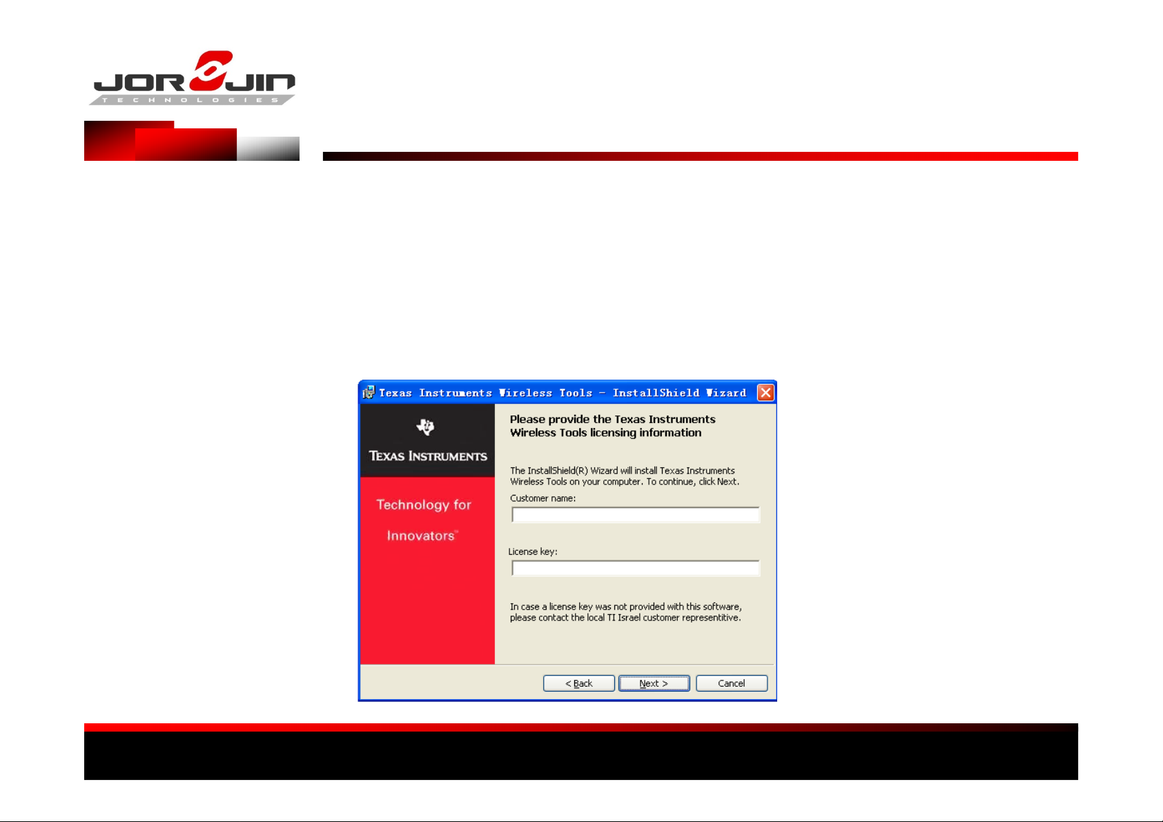
(1) Executive TI Wireless Tools HDK2.0.exe, met process of
following screen , please fill in
Others Were to select the preset
Software lnstallation
Customer name = Random
License Key = 644509802
Page 3
a module solution provider
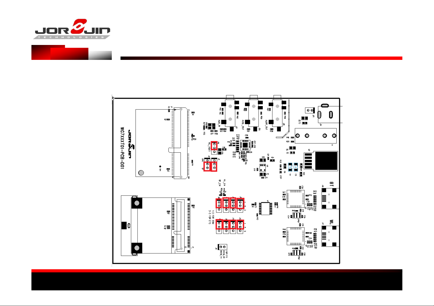
Jumper insertion position for the red box
Transfer Description - 1
Page 4
a module solution provider
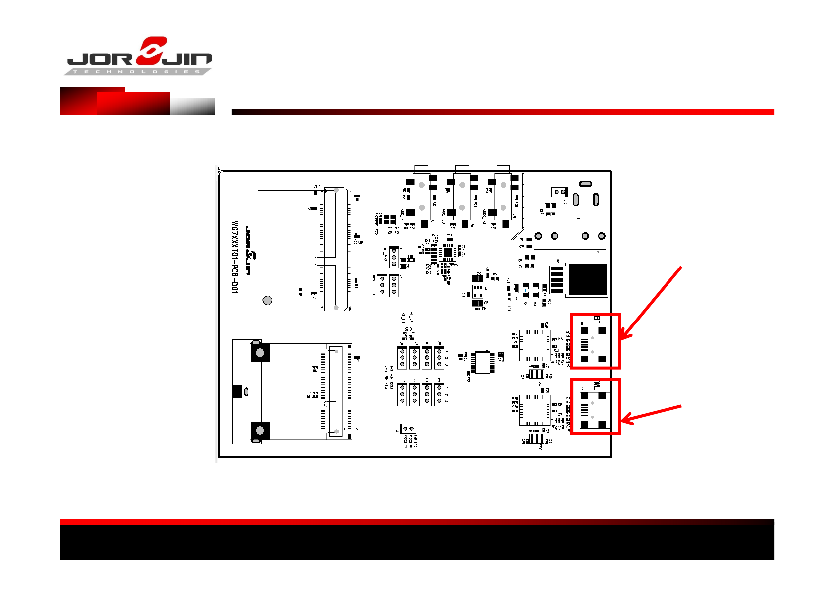
Transfer Description - 2
BT Test
Connection USB
WIFI Test
Connection USB
Page 5
a module solution provider
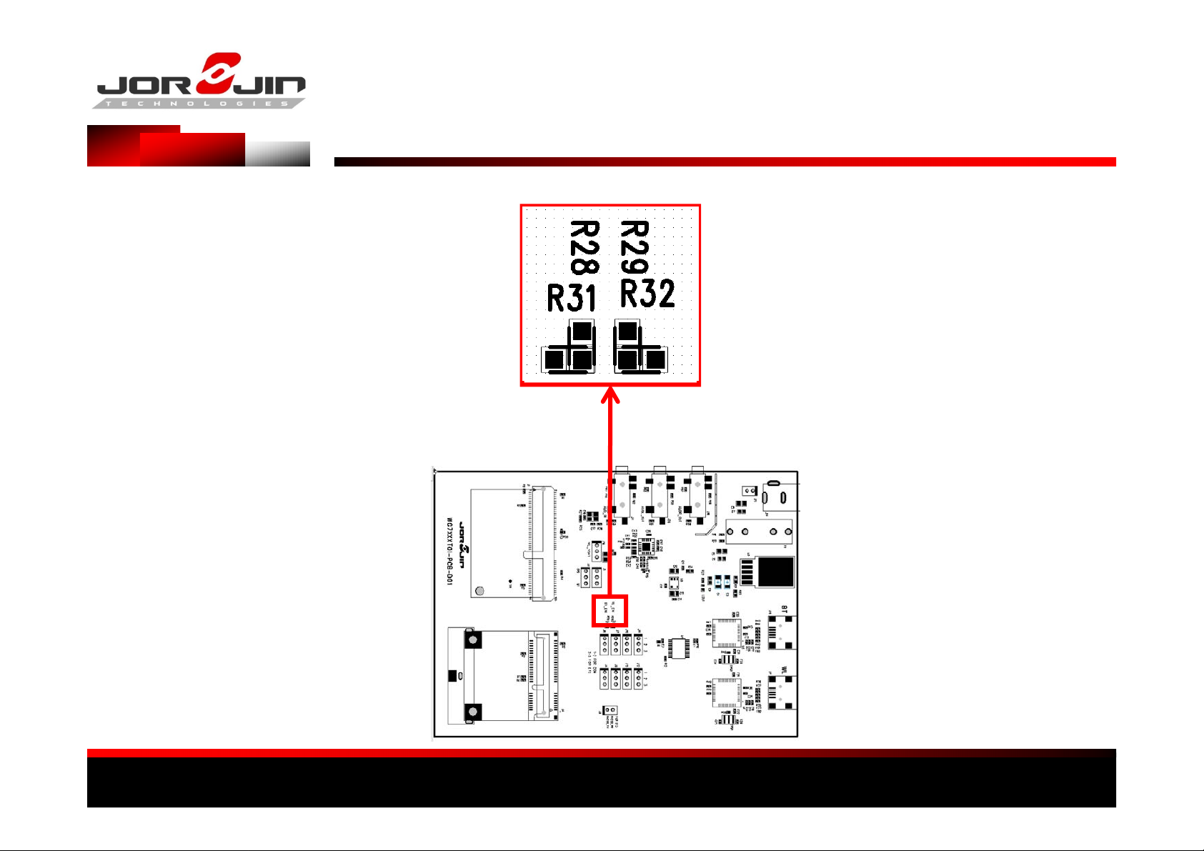
Transfer Description - 3
BT ON : R28
BT OFF : R31
WIFI ON : R29
WIFI OFF : R32
Page 6
a module solution provider
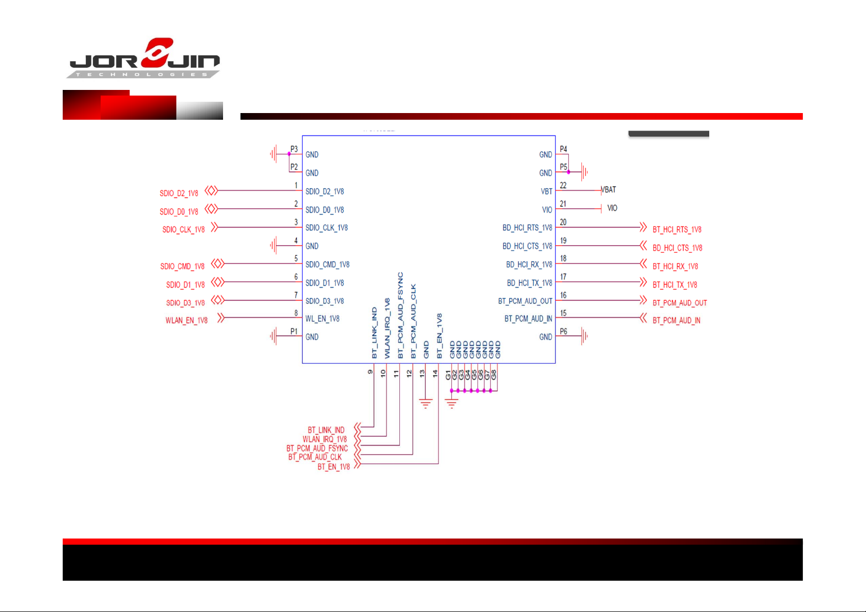
WG7831DELFA
Reference Schematics
Page 7
a module solution provider
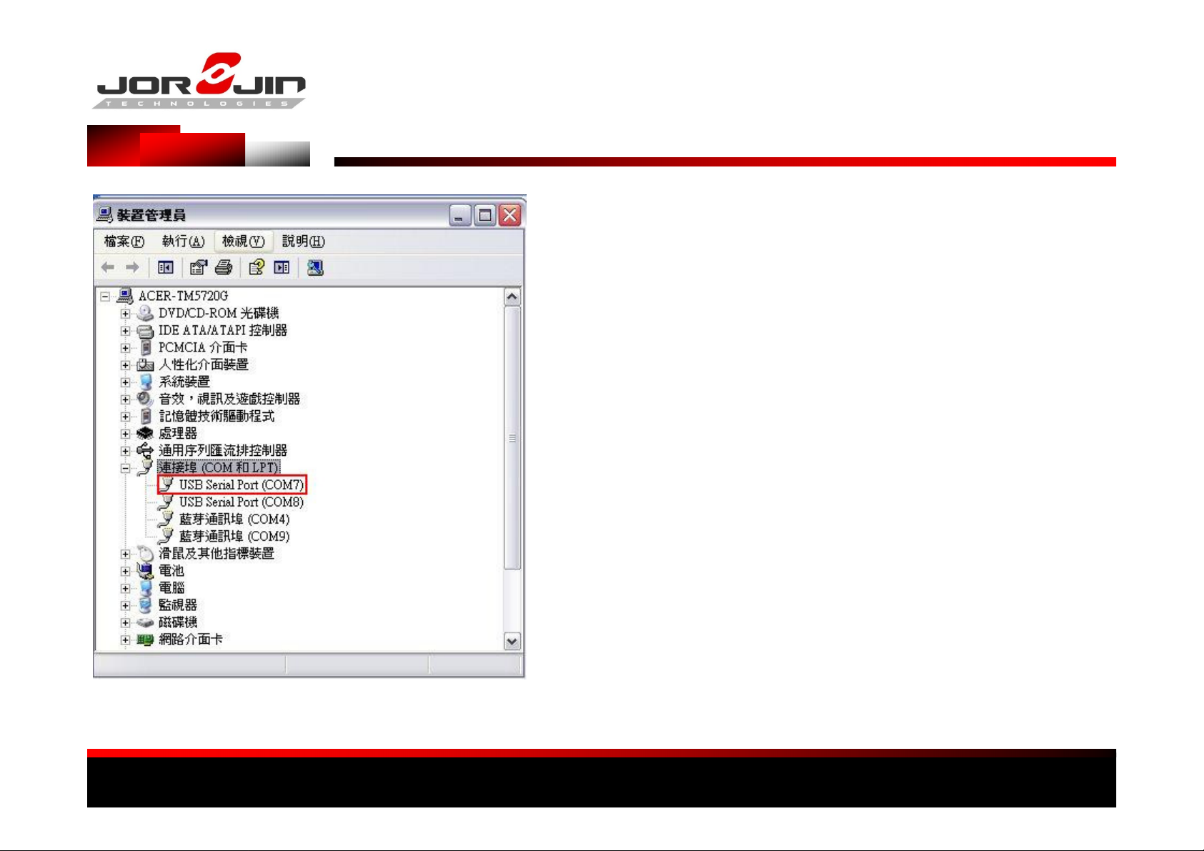
COM PORT Set
1. Install TI Wireless Tools
2. When the hardware is connected to
the PC,
it is possible to find the port number for
communication.
Under the Device Manager, select Ports
(Com & LPT).
3. Run “RTTT” to start WiFi test software.
The USB ports are Com7 and Com8. Normally, the first
port, Com7, is the communication port, while the
next port, Com8, is the debug port.
Page 8
a module solution provider
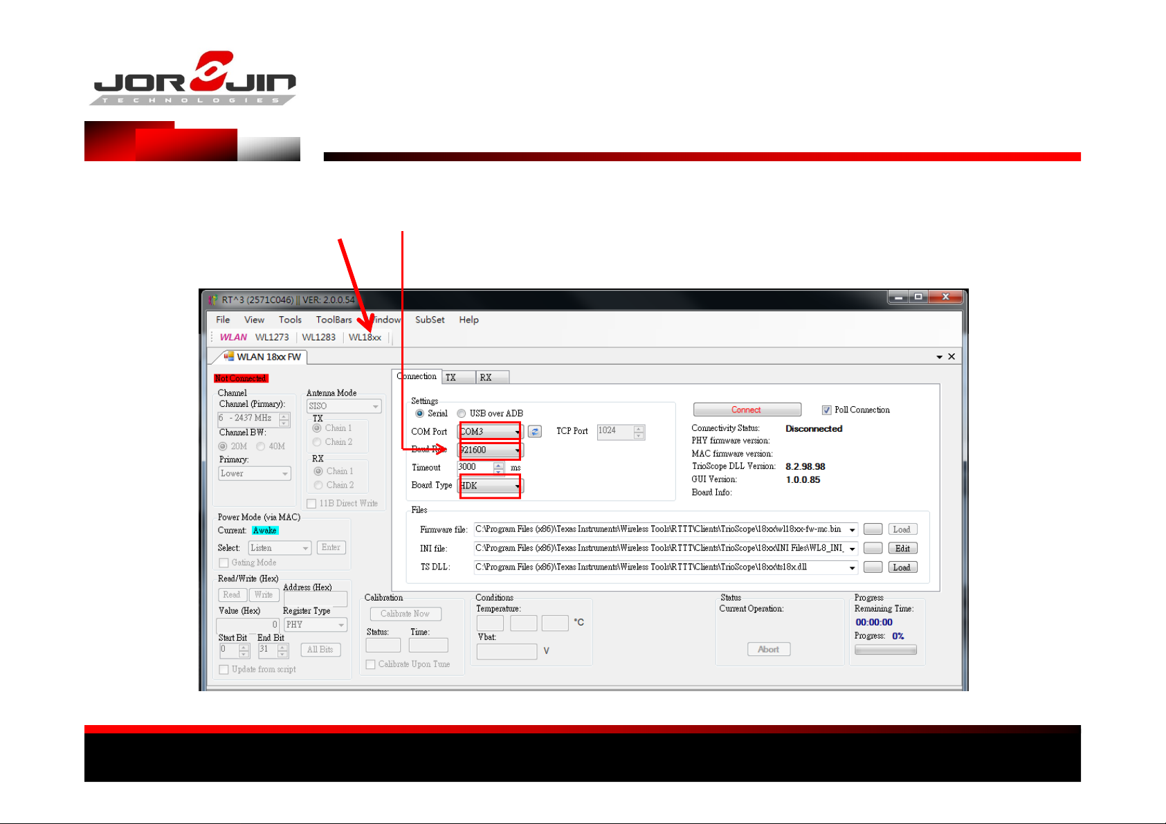
WIFI RTTT SET – 1 (Set time the first operation)
(2) SET COM PORT
(1)Select WL18XX
(3) SET Baud Rate ( 921600 )
(4) SET Board Type : HDK
Page 9

a module solution provider
Set path
Firmware file : C:\Program Files (x86)\Texas Instruments\Wireless Tools\RTTT\Clients\TrioScope\1 8xx\wl18xx-fw-mc.bin
INI file : C:\Program Files (x86)\Texas Instruments\Wireless Tools\RTTT\Clients\TrioScope\18x x\INI Files\WL8_INI_2ANT.ini
TS DLL : C:\Program Files (x86)\Texas Instruments\Wireless Tools\RTTT\ Clients\TrioScope\18xx\ts18x.dll
WIFI RTTT SET – 2 (Set time the first operation)
Page 10

a module solution provider
WIFI RTTT SET – 3
Press Connect
PC Will change of connect
Page 11

a module solution provider
WIFI RTTT SET – 4
Press “Load” Read Firmware
Read Success
Page 12

a module solution provider
SET channel
WIFI RTTT SET – 5
Select TX or RX
Select Modulate and
data rate
SET Power
Select Channel
BW
Set ANT
Start TX ON/OFF
Page 13

a module solution provider
WIFI RTTT SET – 6
NOTE: Chain 1 Express DUT ANT2,
Chain 2 EXpressDUT ANT1
Select dBm, Do not select dBPsat
Click SoC Limits, Power Limit Will be
locked the Dut settings. Power set
30dBm
Page 14

a module solution provider
(1) Execution HCI_Tester
(2) Select View Options
BT HCI Set – 1 (Set time the first operation)
(3) SET COM PORT
and Baud Rate
Page 15

a module solution provider
(1) Add NEW XML檔
BT HCI Set – 2 (Set time the first operation)
Page 16

a module solution provider
BT HCI Set – 3 (Set time the first operation)
(1) Select NEW
(3) Select “ServicePack_18xx_3P1.xml”
(2) Select directory
Page 17

a module solution provider
(1) File Open, Select “ServicePack_18xx_3p1_switch3w_Xtal.txt”
(2) Select Execute Scripts
(3) All instructions execute in sequence
automatically
BT HCI Set – 4
Page 18

a module solution provider
(1) Select File New, CON_TX_TESTER.TXT copy to Script
(2) Select Execute Scripts
(3) All instructions execute in sequence automatically
(4) BT continuous output signal
(5) Perform different signals, must first turn off HCI,repeat BT
Software 1 & 2 in steps
BT HCI Set – 5
Page 19

a module solution provider
Modify different channel ,Power level or modulation,make the following changes to the
parameters
CON_TX_TESTER.TXT-1 parameter modification
# Set frequency 2402M to 2480M #
freq = 2441
# Set power_level 0 to 7#
power_level = 7
# Set modulation type - 0-CW 1-GFSK 2-EDR2 3-EDR3 4-BLE 5-ANT #
modulation = 3
# Set Package type -0x00 DM1
# 0x01 DH1
# 0x02 DM3
# 0x03 DH3
# 0x04 DM5
# 0x05 DH5
# 0x06 2-DH1
# 0x07 2-DH3
# 0x08 2-DH5
# 0x09 3-DH1
# 0x0A 3-DH3
# 0x0B 3-DH5
package_type = 0x09
Page 20

a module solution provider
Different data rate modulation and package_type
parameter indicates
CON_TX_TESTER.TXT-2 parameter modification
Data Rate modulation package_type
DH1 1 0x01
DH3 1 0x03
DH5 1 0x05
2DH1 2 0x06
2DH3 2 0x07
2DH5 2 0x08
3DH1 3 0x09
3DH3 3 0x0A
3DH5 3 0x0B
Page 21

a module solution provider
「本產品內含射頻模組:
The transmitter module certification label
TTTTcccczzzzAI
Page 22

a module solution provider
Your Sole Responsibility and Risk. You acknowledge, represent and agree that:
1.You have unique knowledge concerning Federal, State and local regulatory requirements (including but not limited to Food and
Drug Administration regulations, if applicable) which relate to your products and which relate to your use (and/or that of your
employees, affiliates, contractors or designees) of the EVM for evaluation, testing and other purposes.
2.You have full and exclusive responsibility to assure the safety and compliance of your products with all such laws and other
applicable regulatory requirements, and also to assure the safety of any activities to be conducted by you and/or your employees,
affiliates, contractors or designees, using the EVM. Further, you are responsible to assure that any interfaces (electronic and/or
mechanical) between the EVM and any human body are designed with suitable I solation and means to safely limit accessible
leakage currents to minimize the risk of electrical shock hazard.
3.Since the EVM is not a completed product, it may not meet all applicable regulatory and safety compliance standards (such as UL,
CSA, VDE, CE, RoHS and WEEE) which may normally be associated with similar items. You assume full responsibility to determine
and/or assure compliance with any such standards and related certifications as may be applicable. You will employ reasonable
safeguards to ensure that your use of the EVM will not result in any property damage, injury or death, even if the EVM should fail to
perform as described or expected
4. You will take care of proper disposal and recycling of the EVM’s electronic components and packing materials.
WARNINGS, RESTRICTIONS AND DISCLAIMERS
5. Manual Information to the End User
The OEM integrator h as to be aware no t to pr ovid e in fo rma tio n to the end user rega rd in g how to in stall o r remo ve thi s RF modu le in
the user’s m a n u a l o f th e end product w h i ch integrates this module. The end user manual shall include all required regulatory
information/warning as show in this manual.
Page 23

a module solution provider
6. Federal Communication Commission Interference Statement
This device complies with Part 15 of the FCC Rules. Operation is subject to the following two conditions: (1) This device may not cau se
harmful interference, and (2) this device must accept any interference received, including interference that may cause undesired
operation.
This equipment has been tested and found to comply with the limits for a Class B digital device, pursuant to Part 15 of the FC C Rules.
These limits are designed to provide reasonable protection against harmful interference in a residential installation. This equipment
generates, uses and can radiate radio frequency energy and, if not installed and used in accordance with the instructions, may
cause harmful interference to radio communications. However, there is no guarantee that interference will not occur in a particular
installation. If this equipment does cause harmful interference to radio or television reception , which can be d e te r mined by turning
the equipment off and on, the user is encouraged to try to correct the interference by one of the following measures:
- Reorient or reloca te th e r ec ei vin g a nten na .
- Increase the separation between the equipment and receiver.
- Connect the equipment into an outlet on a circuit different from that to which the receiver is connected.
- Consult the dealer or an experienced radio/TV technician for help.
Any changes or modifications not expressly approved by the party responsible for compliance could void the user's authority to
operate this equipment.
This transmitter must not be co-located or operating in conjunction with any other antenna or transmitter.
7. Industry Canada Statement
This device complies with Industry Canada license-exempt RSS standard(s). Operation is subject to the following two conditions:
(1) this devic e ma y not c au se inte rf e re n c e, and
(2) this device must accept any interference, including interference that may cause undesired operation of the device.
WARNINGS, RESTRICTIONS AND DISCLAIMERS
Le présent appareil est conforme aux CNR d'Industrie Canada applicables aux appareils radio exempts de licence. L'exploitation est
autorisée aux deux conditions suivantes:
(1) l'appareil ne doit pas produire de brouillage, et
(2) l'utilisateur de l'appareil doit accepter tout brouillage radioélectrique subi, même si le brouillage est susceptible d'en
compromettre le fonctionnement."
CAN ICES-3(B)/ NMB-3(B)
8. Radiation Exposure Statement
This equipment complies with FCC/IC radiation exposure limits set forth for an uncontrolled environment. This equipment should be
installed and operated with minimum distance 20 cm between the radiator & your body.
Page 24

a module solution provider
9. End Product Labeling
When the module is installed in the host device, the FCC/IC ID label must be visible through a window on the final device or it must
be visible when an access panel, door or cover is easily re-moved. If not, a second label must be plac ed on the outside of the final
device that contains the following text: “Contains FCC ID: QDX31511” “Contains IC: 4810A-31511 “
The grantee's FCC ID/IC ID can be used only when all FCC/IC compliance requirements are met.
10. This device is intended only for OEM integrators under the following conditions:
(1) The antenna must be ins talled suc h that 20cm is main tai ned betwee n th e ante nna and users ,
(2) The transmitter module may not be co-located with any other transmitter or antenna.
(3) The chip antenna with -2.46 dBi gain was verified in the conformity testing. Radiated transmit power must be equal to or lower
than that specified in the FCC/IC Grant of Equipment Authorization for FCC ID: QDX31511 and IC: 4810A-31511. A separate approval
is required for all other antenna type, or higher gain antenna.
In the event that these conditions cannot be met (for example certain laptop configurations or co-location with another transmitter),
then the FCC/IC authorization is no longer considered valid and the FCC ID/IC ID c a n n o t b e use d on the fin a l pr o duct. In these
circumstances , the OEM integr ato r wi ll be resp ons ib le fo r re-e valua ting the end produ ct ( in cludi ng the transmit ter ) and obtain ing a
separate FC C/ IC au tho r iz a tio n .
WARNINGS, RESTRICTIONS AND DISCLAIMERS
 Loading...