

Page 1
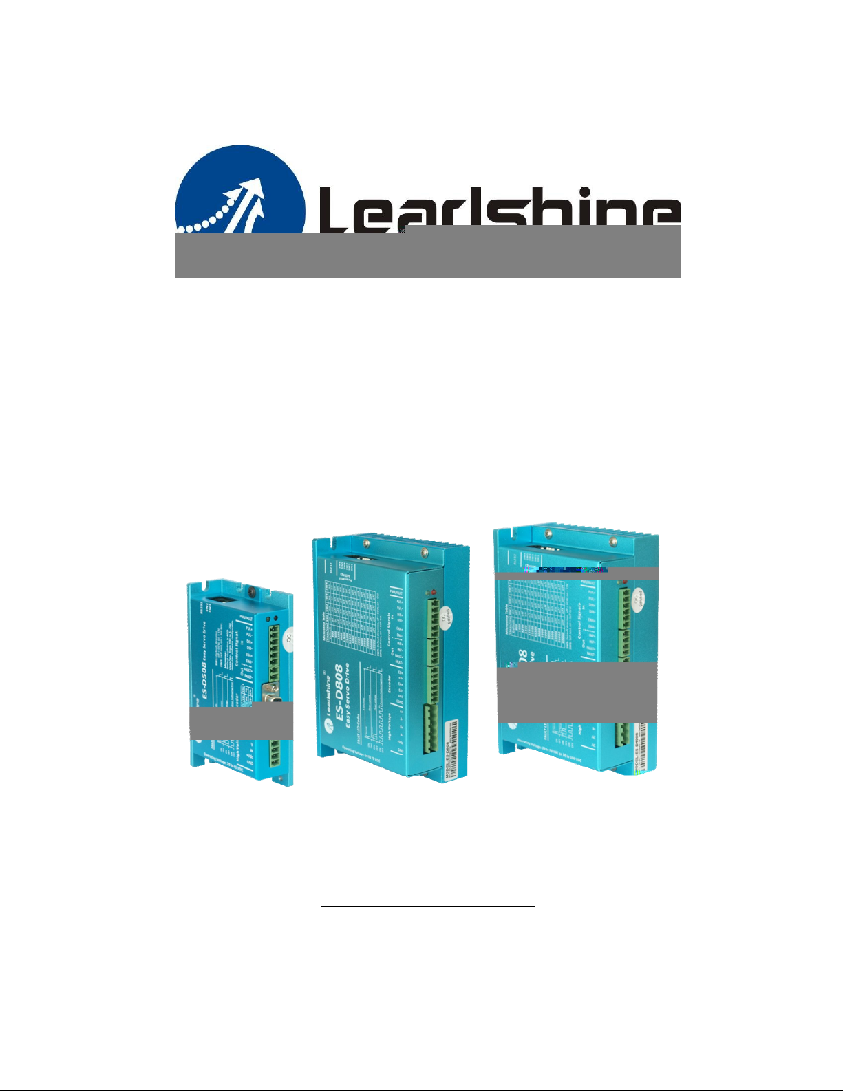
Hardware Manual of the Easy Servo Drives
ES-D508, ES-D808 & ES-D1008
Version 1.1
http://www.Leadshine.com
http://www.Leadshineusa.com
©2013 Leadshine Technology Co., Ltd.
Page 2
Safety Items
!
Notice
!
Caution
!
Warning
ii
Read this manual carefully before trying to install the stepper drive into your
system. The people who setup the stepper drive should have a better
understanding on electronics and mechanics. Contact Leadshine technical guys
when you have questions on this document.
Make sure the power supply voltage dose not exceed the drive’s input range.
Double check the connections and make sure the power lead polarity is correct.
Do not set high current for small stepper motor. It is possible that the motor will be
damaged.
!
Caution
!
Warning
Disconnect the motor from the load if you are not sure the move direction. Adjust
the axis in the center before trying to run the motor.
Never disconnect the motor lead when the power source is energized.
Page 3

iii
Table of Contents
Introduction to the Easy Servo.......................................................................................................................................1
Getting Start ...................................................................................................................................................................1
Wiring Diagrams.....................................................................................................................................................4
Connecting Power Supply.......................................................................................................................................5
ES-D508 and ES-D808......................................................................................................................................5
ES-D1008 .........................................................................................................................................................5
Connecting Motor...................................................................................................................................................6
ES-D508 and ES-M3 Series Motor...................................................................................................................6
ES-D808 / ES-D1008 and ES-M2 Series Motors ..............................................................................................6
Connecting Encoder................................................................................................................................................7
ES-D508 and ES-M3 series motors..................................................................................................................7
ES-D808/ ES-D1008 and ES-M2 series motors................................................................................................7
Connecting Control Signal......................................................................................................................................8
Pulse, Direction, Enable Input Connections....................................................................................................8
Fault, In-position Output Connections ...........................................................................................................9
Connecting PC.......................................................................................................................................................10
Typical Connections.......................................................................................................................................................11
Wiring Notes.................................................................................................................................................................12
Configuration................................................................................................................................................................13
Configuring ES drive by the DIP Switches.............................................................................................................14
ES-D508 .........................................................................................................................................................14
ES-D808 / ES-D1008 ......................................................................................................................................14
Configuring ES drive in the PC Software ..............................................................................................................15
Rotating the Motor.......................................................................................................................................................16
Calculating Rotation Speed and Angle.................................................................................................................16
Rotating the Motor by Motion Controller............................................................................................................16
Rotating the Motor in Self-test Mode..................................................................................................................16
Rotating the Motor in PC Software......................................................................................................................16
Power Supply Selection.................................................................................................................................................17
Regulated or Unregulated Power Supply.............................................................................................................17
Multiple Drives......................................................................................................................................................18
Selecting Supply Voltage......................................................................................................................................18
Recommended Supply Voltage.............................................................................................................................18
Control Signal Setup Timing.........................................................................................................................................19
Current Control Detail...................................................................................................................................................19
Fine Tuning....................................................................................................................................................................20
Protection Functions.....................................................................................................................................................20
Over-current Protection........................................................................................................................................20
Over-voltage Protection .......................................................................................................................................20
Position Following Error Protection .....................................................................................................................21
Page 4

iv
Frequently Asked Questions.........................................................................................................................................21
Problem Symptoms and Possible Causes.............................................................................................................21
Warranty.......................................................................................................................................................................22
Exclusions..............................................................................................................................................................22
Obtaining Warranty Service.................................................................................................................................22
Warranty Limitations............................................................................................................................................22
Shipping Failed Product........................................................................................................................................22
Contact Us.....................................................................................................................................................................23
Page 5
Hardware Manual of the ES-D Series Drives
Introduction to the Easy Servo
The ES (easy servo) series easy servos offer an alternative for applications requiring high performance
and high reliability when the traditional servo was the only choice, while it remains cost-effective.
The system includes an easy servo motor combined with a fully digital, high performance easy servo
drive. The internal encoder is used to close the position, velocity and current loops in real time, just
like servo systems. It combines the best of servo and stepper motor technologies, and delivers unique
many capabilities and enhancements over both, while at a fraction of the cost of a servo system.
Easy Servo Drive
Easy Servo Moto
Getting Start
To get start you need one easy servo drive, one easy servo motor (stepper motor with encoder) and
an AC / DC power supply to set up a minimum easy servo system. A motion controller - like indexer,
pulse generator or PLC is required too when you need to rotate the motor. If you have a PC with one
serial port or one PC with USB-RS232 converter, you can also rotate the motor via PC software,
ProTuner. However it is recommended to verify all function of an easy servo with a motion controller.
1
Page 6
Hardware Manual of the ES-D Series Drives
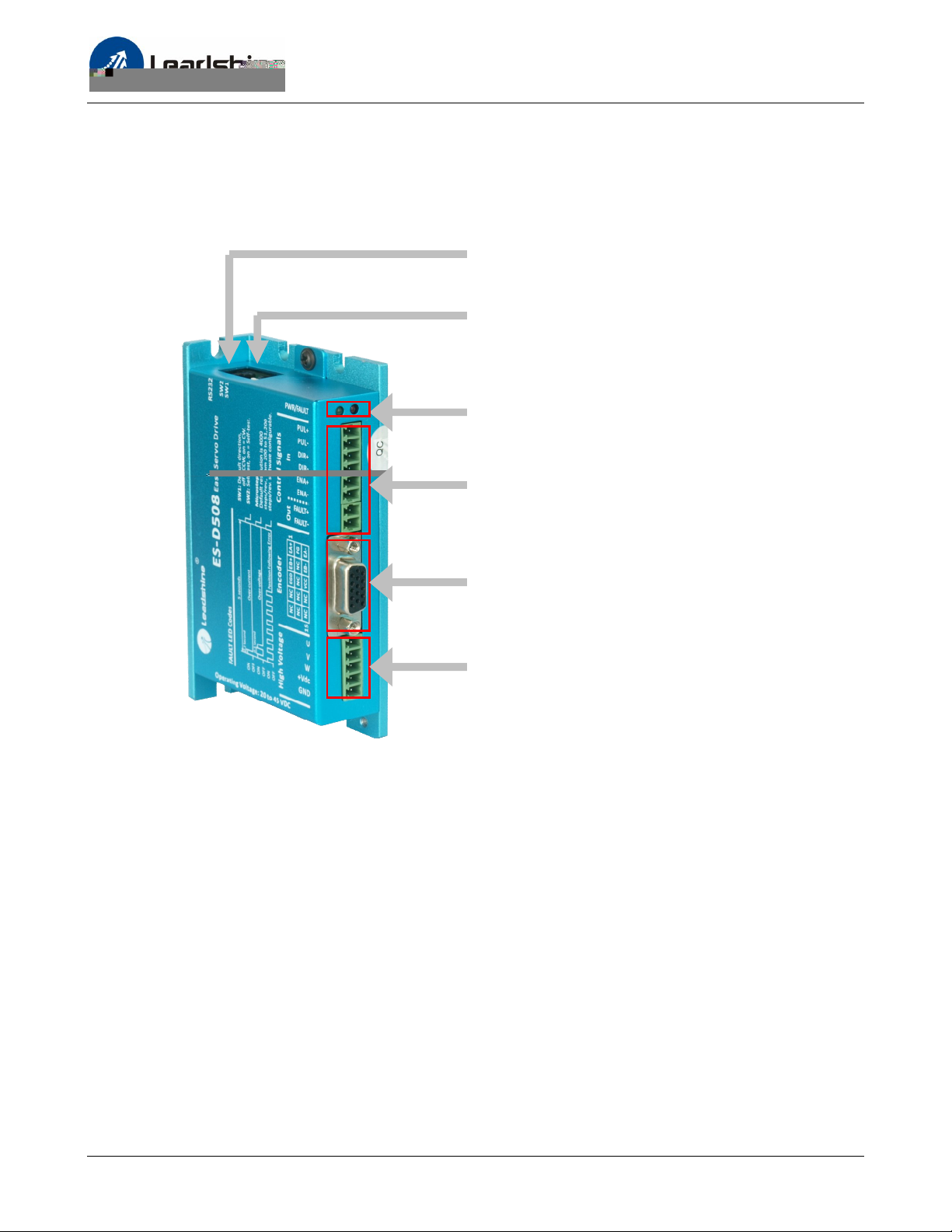
Drive Appearance and Connector Location
ES-D508
RS232 Communication Connector
(RJ11)
2-bit DIP Switch
(SW1: Direction, SW2: Self-test)
(Green LED: Power, Red LED: Fault)
Indicator
Control signals connectors including digital
inputs and digital outputs
(Screw Terminal Blocks)
Encoder feedback signals connector
(HDD15)
Power & motor connector
(Screw Terminal Block)
Drive appearance and connector location of the ES-D508
2
Page 7
Hardware Manual of the ES-D Series Drives
Drive Appearance and Connector Location (Continued)
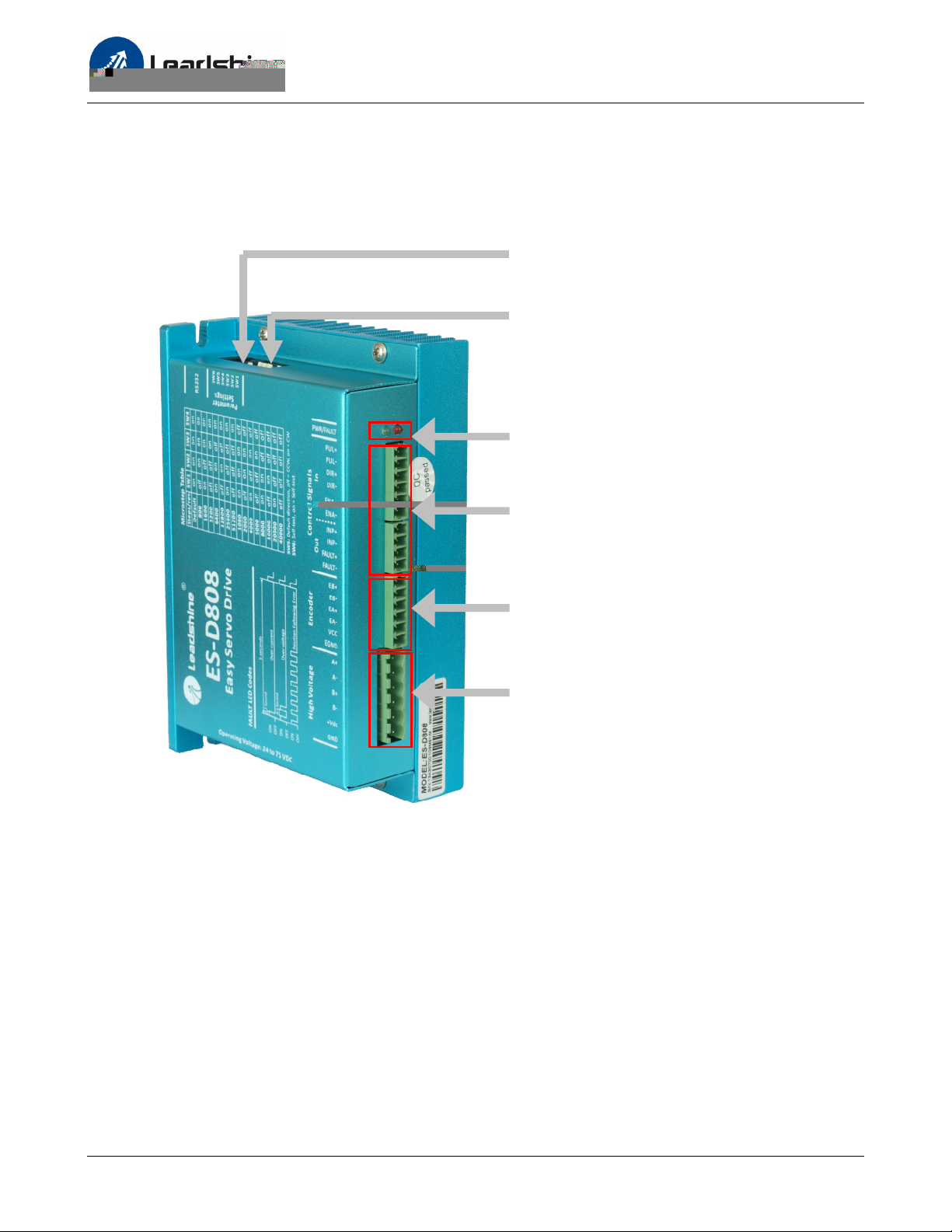
ES-D808 / ES-D1008
RS232 Communication Connector
(RJ11)
6-bit DIP Switch
(SW1-4: Micro Step, SW5: Direction, SW6: Self-test)
Indicator
(Green LED: Power, Red LED: Fault)
Control signals connectors including digital
inputs and digital outputs
(Screw Terminal Block)
Encoder feedback signals connector
(Screw Terminal Block)
Power & motor connector
(Screw Terminal Block)
Drive appearance and connector location of the ES-D808 / ES-D1008
3
Page 8
Wiring Diagrams
Hardware Manual of the ES-D Series Drives
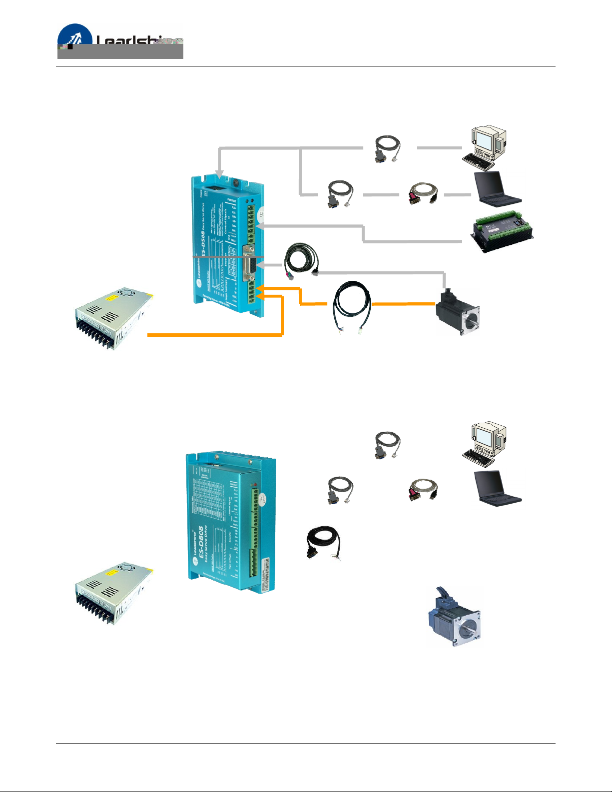
RS232 Cable
Or
USB-232 Converter
Motion Controller
Power Supply
Encoder Cable * (must be used)
Power Extension Cable
Wiring diagram of the ES-D508 and ES-M3 series motors
Wiring diagram of the ES-D808 / ES-D1008 and ES-M2 series motors
4
Page 9
Hardware Manual of the ES-D Series Drives
AC
AC Power
20-70VAC
DC Power
30-100VDC
-
(Negative)
-
(Negative)
Connecting Power Supply
ES-D508 and ES-D808
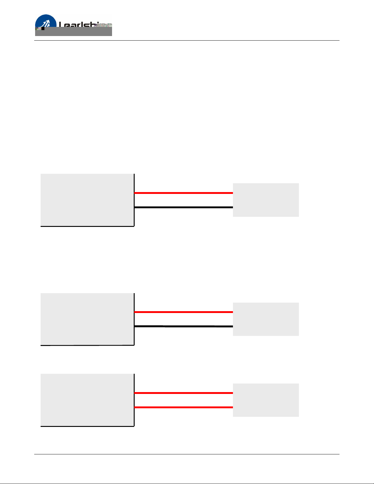
The ES-D508 and ES-D808 only accept DC power input. The power supply connections include only
one positive terminal and one negative terminal. However you need to pay attention to terminal
polarity. A 6-pin pluggable screw connector is used for both power supply and motor connections.
Looking at the drive cover you should find the printed “+Vdc” and “GND” symbol. Connect the
positive wire to “+Vdc” terminal and connect the negative wire to “GND” terminal. Note that the
power should be switched off when you make any connections.
Note: Do not exceed the input voltage range of the easy servo drive. Please consult the “Power
Supply Selection” chapter for the recommended supply voltage.
+ (Positive)
+Vdc
High Voltage DC Power
GND
DC Power Connection of the ES-D508 and ES-D808
ES-D1008
The ES-D1008 can accept DC or AC power input. There is no power input polarity for the AC power
connection.
+ (Positive)
AC
High Voltage
AC
DC power connection of the ES-D1008
AC
AC
High Voltage
AC
AC power connection of the ES-D1008
5
Page 10
Hardware Manual of the ES-D Series Drives
Connecting Motor
ES-D508 and ES-M3 Series Motor
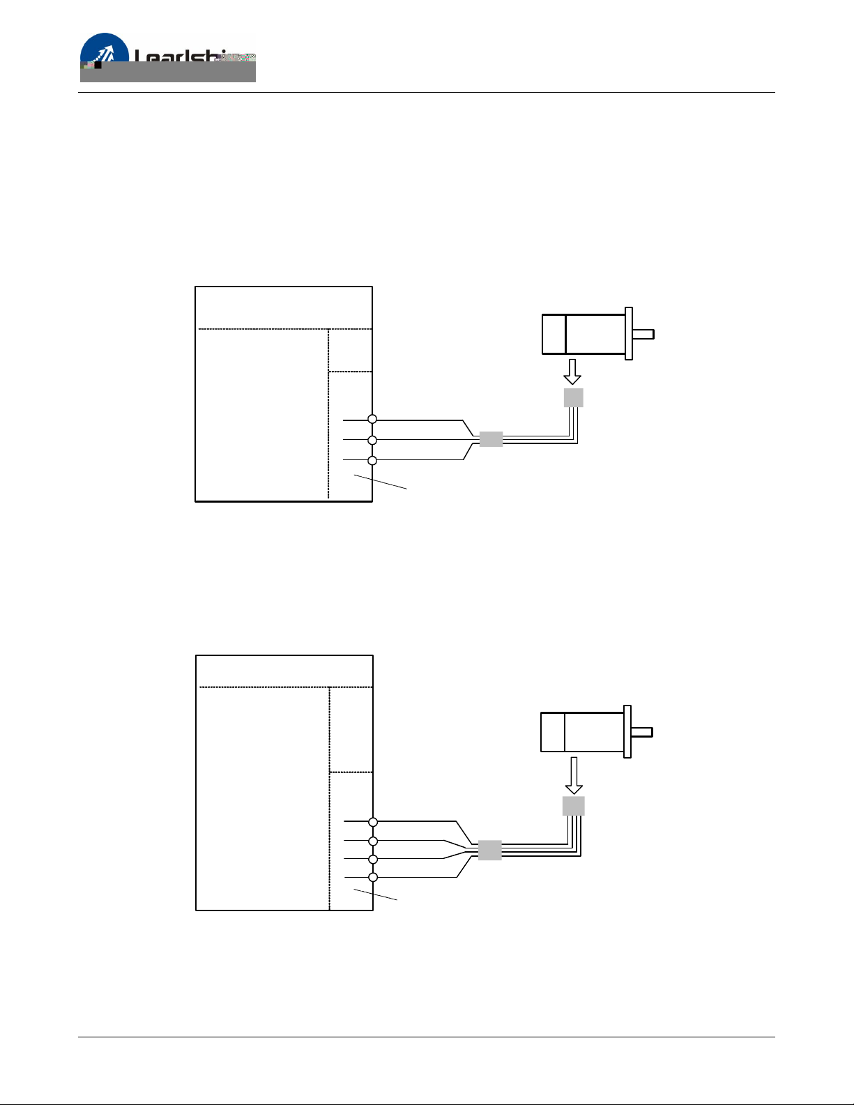
A power extension cable is needed to be connected between the ES-M3 series motors and the
ES-D508. One end of this power extension cable includes four flying wires. You can connect these
wires to the drive’s corresponding terminals as follows. Just cut off the yellow/green wire or leave it
unconnected.
ES-M32309
ES-D508
ES-M32320
Power
Cable
U
1
2
3
Red
V
Blue
W
Black
Power &
Motor Connector
Power
Extension Cable*
*leave the yellow/green
wire unconnected
Connect Leadshine ES-M3 series motors to ES-D508
ES-D808 / ES-D1008 and ES-M2 Series Motors
A power extension cable is needed to be connected between the ES-M2 series motor and the
ES-D808 / ES-D808. One end of this power extension cable includes four flying wires. You can connect
these wires to the drive’s corresponding terminals as follows.
ES-D808 / ES-D1008
A+
1
2
3
4
Black
A-
Red
Yellow/ Green
B+
B-
Blue
Power
Extension Cable
ES-M22430
ES-M23440
ES-M23480
Power
Cable
Power & Motor Connector
Connect Leadshine ES-M2 series motors to ES-D808 / ES-D1008
6
Page 11
Hardware Manual of the ES-D Series Drives
Connecting Encoder
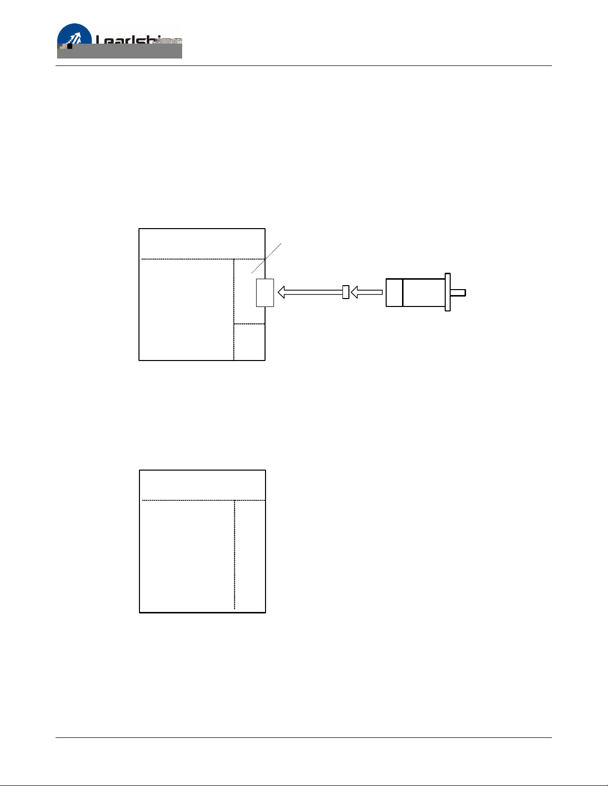
As the easy servo drive works in close-loop mode, it needs to know the actual motor position. The
encoder mounted on the motor offers such information. Please note that the easy servo drive can
not work without encoder feedback.
ES-D508 and ES-M3 series motors
The encoder extension cable is required to connect the motor and ES-D508. The drive will not work
properly if you connect the motor’s encoder cable to the ES-D508 directly.
Encoder Signal
ES-D508
Connector
Encoder
Extension Cable*
*must be used
ES-M32309
ES-M32320
Encoder
Cable
Encoder connections between the ES-D508 and ES-M3 series motors
ES-D808/ ES-D1008 and ES-M2 series motors
The encoder output of the ES-M2 series motor is a HDD15 connector while the encoder input of the
ES-D808 / ES-D1008 is screw terminal, so an extension cable is required between the drive and
motor.
ES-D808 / ES-D1008
Encoder Signal
Connector
7
Page 12
Hardware Manual of the ES-D Series Drives
Connecting Control Signal
Pulse, Direction, Enable Input Connections
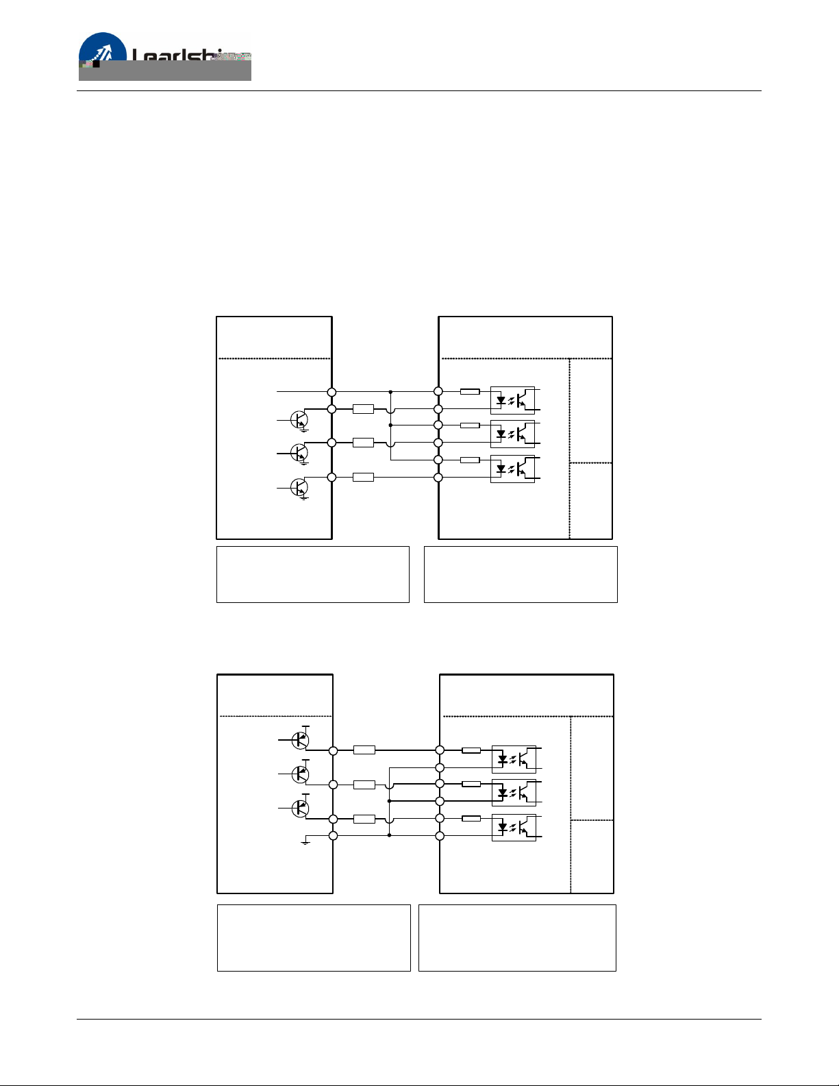
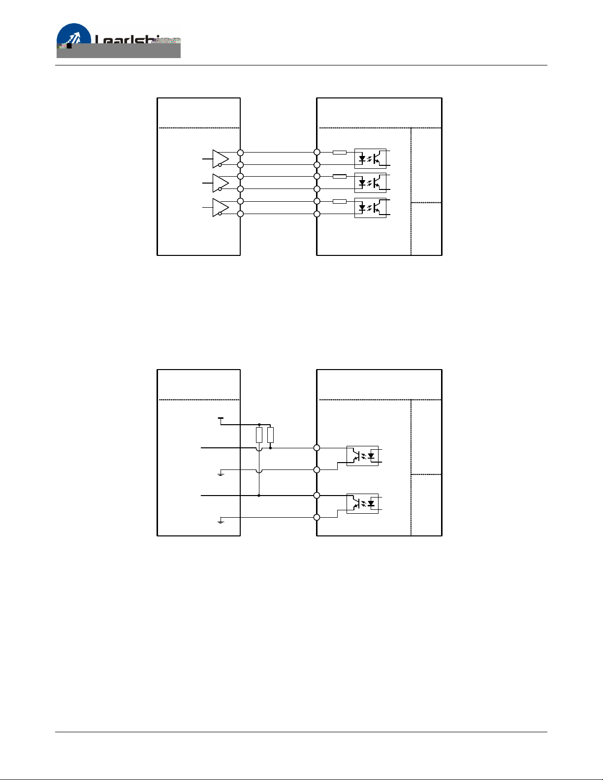
The ES-D series drives can accept differential, PNP(sourcing) and NPN(sinking) pulse, direction and
enable control signals. For the enable signal, apply 0V between ENA+ and ENA- or leave them
unconnected to enable the drive. Recommend to leave the enable signal unconnected if you don’t
need to disable the drive.
In a NPN (sinking) type output, the control signals share the same positive terminal.
Controller
VCC
Step
Direction
Enable
PUL+
R
R
R
PULDIR+ 3
DIR-
ENA+ 5
ENA-
ES-D Drive
1
2
4
6
Control Signal
Connector
ES-D508
R=0 if VCC=5V;
R=1K(Power>0.125W) if VCC=12V;
R=2K(Power>0.125W) if VCC=24V;
R must be connected to control signal terminal.
ES-D808 / ES-D1008
VCC =5~24V. R is not required.
Connect the ES-D drives to the NPN (sinking) type controllers
In a PNP (sourcing) type output, the control signals are refer to the same ground terminal.
ES-D DriveController
Step
Direction
Enable
VCC
VCC
VCC
R
R
R
PUL+
PULDIR+ 3
DIR-
ENA+ 5
ENA-
1
2
4
6
Control Signal
Connector
ES-D508
R=0 if VCC=5V;
R=1K(Power>0.125W) if VCC=12V;
R=2K(Power>0.125W) if VCC=24V;
R must be connected to control signal terminal.
ES-D808 / ES-D1008
VCC =5~24V. R is not required.
Connect the ES-D drives to the PNP (sourcing) type controllers
8
Page 13
Hardware Manual of the ES-D Series Drives
Pulse, Direction, Enable Input Connections (Continued)
ES-D DriveController
Step
Direction
Enable
5V
PUL+
PULDIR+ 3
DIR-
ENA+ 5
ENA-
1
2
4
6
Control Signal
Connector
Connect the ES-D drives to differential type controllers
Fault, In-position Output Connections
The outputs are isolated and you can take them as electronic switch. An upper resistor is used to limit
the current. Its resistance is depending on the input current requirement of the controller. The source
voltage for those outputs can also be 24V. The resistor R is depending on the input current of the
controller.
Controller
5V
Fault
R
R
FAULT+
ES-D Drive
Control Signal
Connector
FAULT-
In-position
INP+
INP-
Fault, in-position signal connection of the ES-D drive
(Note: The ES-D508 does not have in-position output)
9
Page 14
Hardware Manual of the ES-D Series Drives
Connecting PC
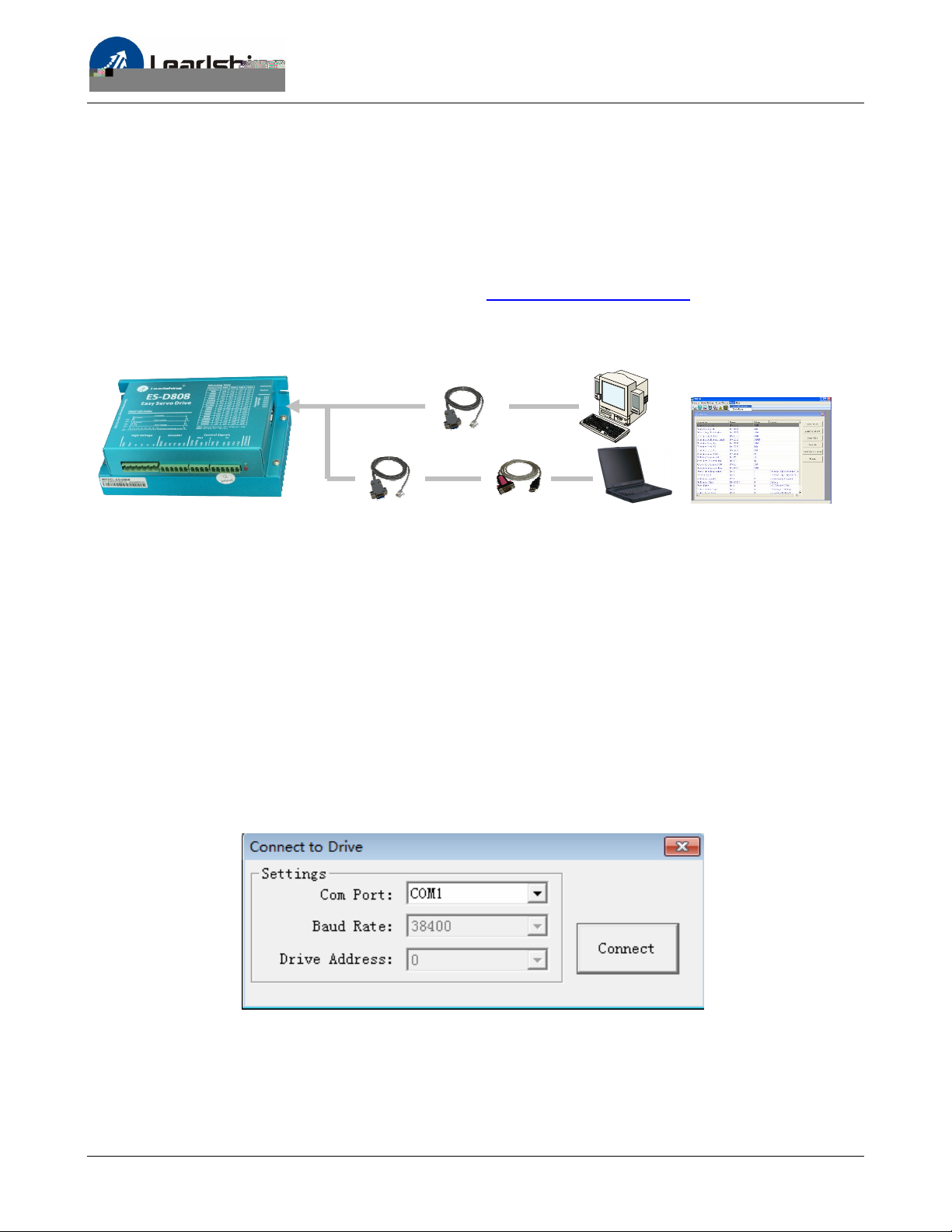
There is a built-in RS232 port in each easy servo drive for communication and configuration. Connect
this port to the PC’s serial port. Then you can rotate the motor in the setup software. This setup
software - ProTuner, is designed to configure the easy servo drive. You can define the control mode,
microstep resolution, current rate, active level of inputs/outputs in ProTuner.
The ProTuner can be downloaded from our website: http://www.leadshine.com or you may also get it
from our CD. It is recommended to get it from the website because software from the website is
always the latest. Install it in your PC and make it ready for use later.
RS232 Cable
Or
USB-232 Converter
ProTuner
Connect ES-D808 / ES-D1008 to PC
A RS232 cable is needed for the communication between the drives and the ProTuner. It will be
shipped with the kit if you include it in the order. It is also possible to make this cable by yourself. One
end of this cable is a RJ-11 header and the other end of cable is a 9 pin D-Sub female connector. If
your PC does not have a serial port, a USB-to-232 converter is required.
Note: The power should be turned off when you perform any connections!
When you open ProTuner, a “Connect to drive” window appears. The “Baud Rate” and “Device
Address” are fixed. You only need to select the “Com Port” according to the actual serial port or the
mapping port of a USB-232 converter. Check the Device Manager for the mapping port number of
the USB-232 converter.
10
Page 15
Hardware Manual of the ES-D Series Drives
Typical Connections
Controller
VCC
Step
Direction
Enable
5V
Fault
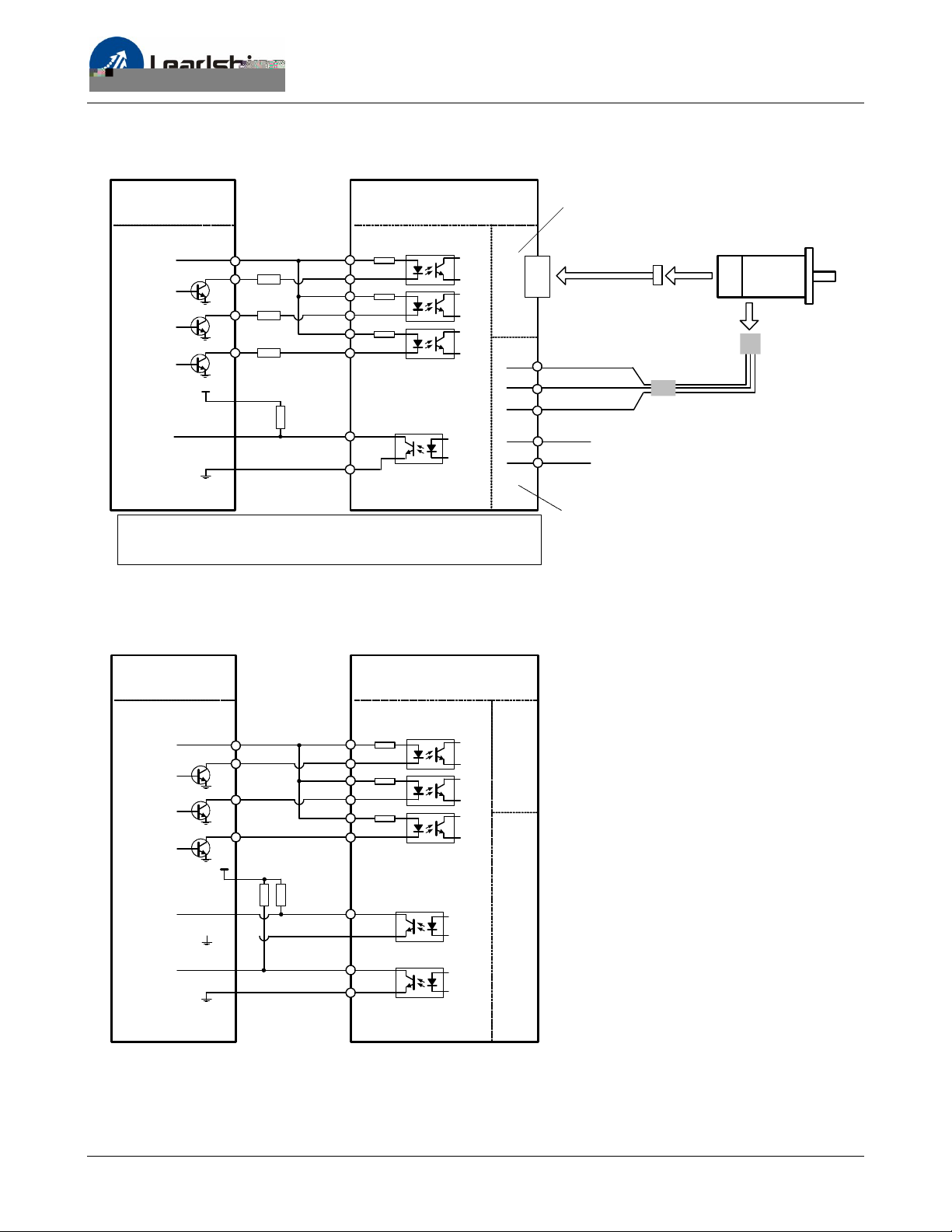
R=0 if VCC=5V;
R=1K(Power>0.125W) if VCC=12V;
R=2K(Power>0.125W) if VCC=24V;
R must be connected to control signal terminal.
ES-D508
Encoder Signal
Connector
PUL+
R
R
R
PULDIR+ 3
DIR-
ENA+ 5
ENA-
FAULT+
FAULT-
1
2
4
6
Control Signal
Connector
7
8
1
2
3
4
5
Encoder
Extension Cable*
*must be used
U
Red
V
Blue
W
Black
+Vdc
GND
20-45VDC recommended,
leaving rooms for voltage fluctuation
and back EMF of the motor
Encoder
Cable
Power
Extension Cable*
*leave the yellow/green
wire unconnected
Power &
Motor Connector
Typical connections of the ES-D508 with controller of sinking output
ES-M32309
ES-M32320
Power
Cable
Controller
5-24V
5V recommended
Step
Direction
Enable
In-Position
Fault
ES-D808
PUL+
PULDIR+ 3
DIR-
ENA+ 5
ENA-
5V
INP+ 1
FAULT+ 3
FAULT-
1
2
4
6
2INP-
4
Stat
11
Page 16
Hardware Manual of the ES-D Series Drives
Typical Connections (Continued)
Controller
5-24V
5V recommended
Step
Direction
Enable
In-Position
Fault
ES-D1008
Control Signal
Connector
PUL+
PULDIR+ 3
DIR-
ENA+ 5
ENA-
5V
INP+ 1
FAULT+ 3
FAULT-
1
2
4
6
2INP-
4
Status Signal
Connector
Encoder Signal
Connector
Encoder
Extension Cable*
*must be used
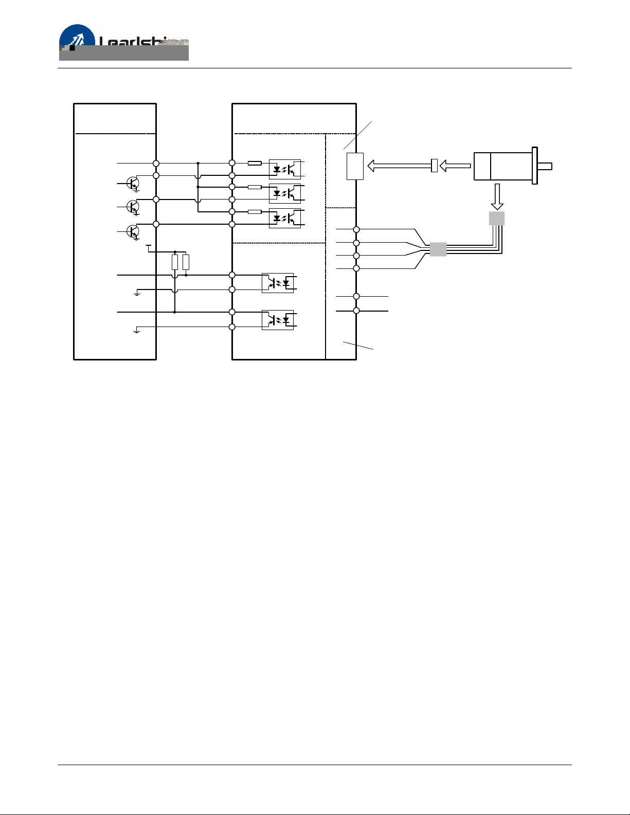
EA+: BLK EA-: BLU
EB+: YEL EB-: GRN
+5V: RED GND: WHT
A+
1
2
3
4
5
6
Black
A-
Red
Yellow/ Green
B+
Blue
B-
AC
AC
Power &
Motor Connector
20-70VAC or 30-100VDC
Typical Connections of the ES-D1008 with controller of sinking output
ES-M23440
ES-M23480
Encoder
Cable
Power
Cable
Power
Extension Cable
Wiring Notes
l In order to improve anti-interference performance of the system, it is recommended to use
twisted pair shield cable.
l To prevent noise incurred in PUL/DIR signal, pulse/direction signal wires and motor wires should
not be tied up together. It is better to separate them by at least 10 cm, otherwise the disturbing
signals generated by motor will easily disturb pulse direction signals, causing motor position
error, system instability or other failures.
l If a power supply serves several drives, separately connecting the drives is recommended instead
of daisy-chaining.
l It is prohibited to pull and plug power connector while the drive is powered ON, because there is
high current flowing through motor coils (even when motor is at standstill). Pulling or plugging
power connector with power on will cause extremely high back-EMF voltage surge, which may
damage the drive.
12
Page 17
Hardware Manual of the ES-D Series Drives
Configuration
When the default settings of the easy servo drive are not suitable for your application, it is necessary
to configure the drive via the DIP switch or ProTuner (the setup software). Otherwise you may
encounter problems like high motor heating, big motor noise or even motor stall due to weak torque.
For a quick start of the easy servo drive, there are not much parameters need to be configured. The
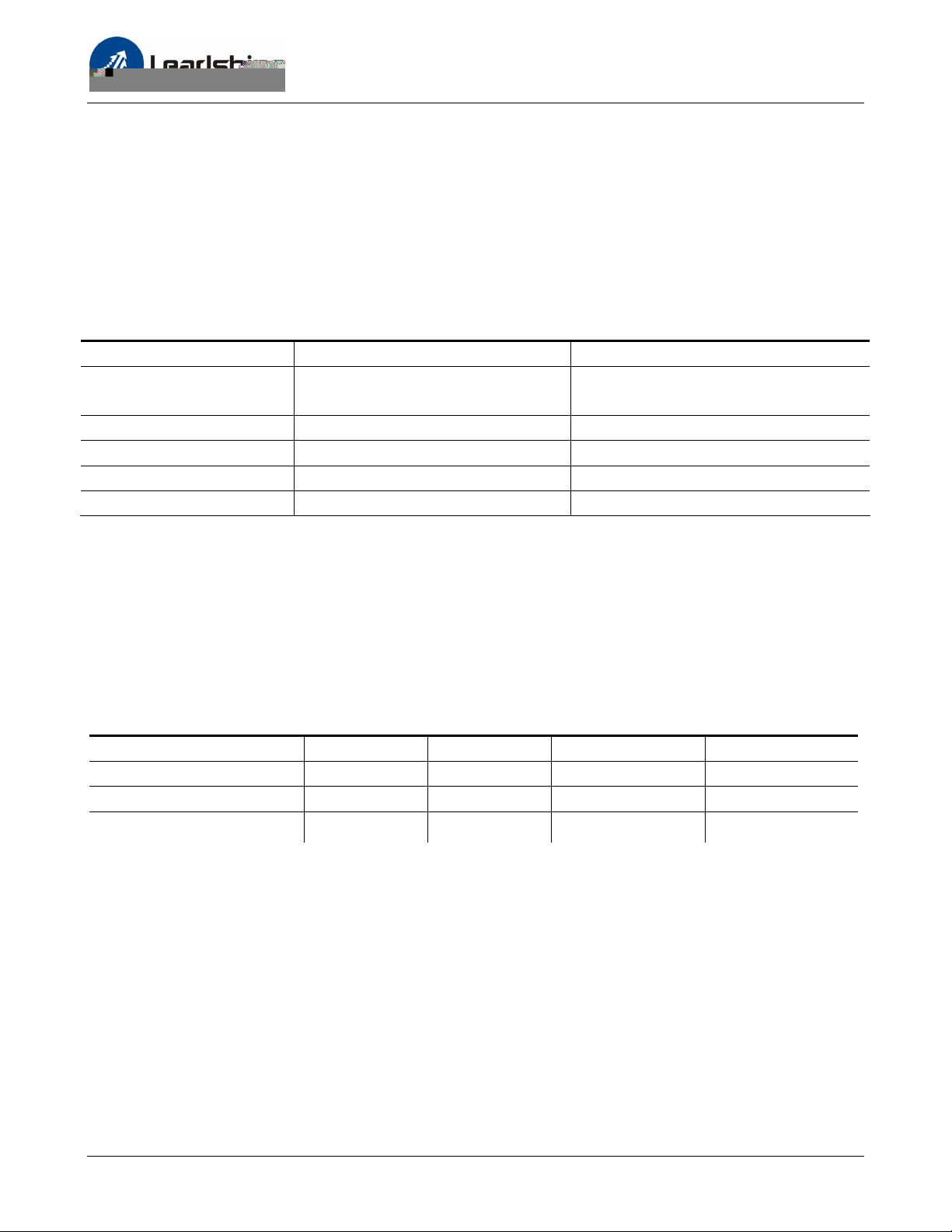
following table gives the most significant parameters of the easy servo drive.
Most Significant Parameters of the easy servo drive
Parameters ES-D508 ES-D808, ES-D1008
Micro Step Resolution (PPR) Default 4000, Software Adjustable Default 1600, DIP Switch or Software
Adjustable
Holding Current (%) Default 40%, Software Adjustable Default 50%, Software Adjustable
Close-loop Current (%) Default 100% , Software Adjustable Default 100%, Software Adjustable
Current Loop Kp *Auto Tuning at Power-up *Auto Tuning at Power-up
Current Loop Ki *Auto Tuning at Power-up *Auto Tuning at Power-up
*Auto Tuning at Power-up: It is possible to disable this feature in the setup software in order to tune
the current loop Kp and current loop Ki manually if the auto tuning result is not good enough. This
happens when the motor’s inductance or resistance is too high or too low.
The holding current affects the holding torque when the motor is stop. The close-loop current affects
the dynamic torque. Increase them if the torque is not enough.
Recommended Holding / Close-loop Current Percentage
ES-M32309 ES-M32320 ES-M23440 ES-M23480
Holding Current (%) 60% 60% 60% 60%
Close-loop Current (%) 100% 100% 100% 100%
Easy servo drive
ES-D508 ES-D508 ES-D808 / ES-D1008 ES-D808 / ES-D1008
There are possible two methods to configure the easy servo drive as follows, depending on the
specific drive.
13
Page 18
Hardware Manual of the ES-D Series Drives
Configuring ES drive by the DIP Switches
ES-D508
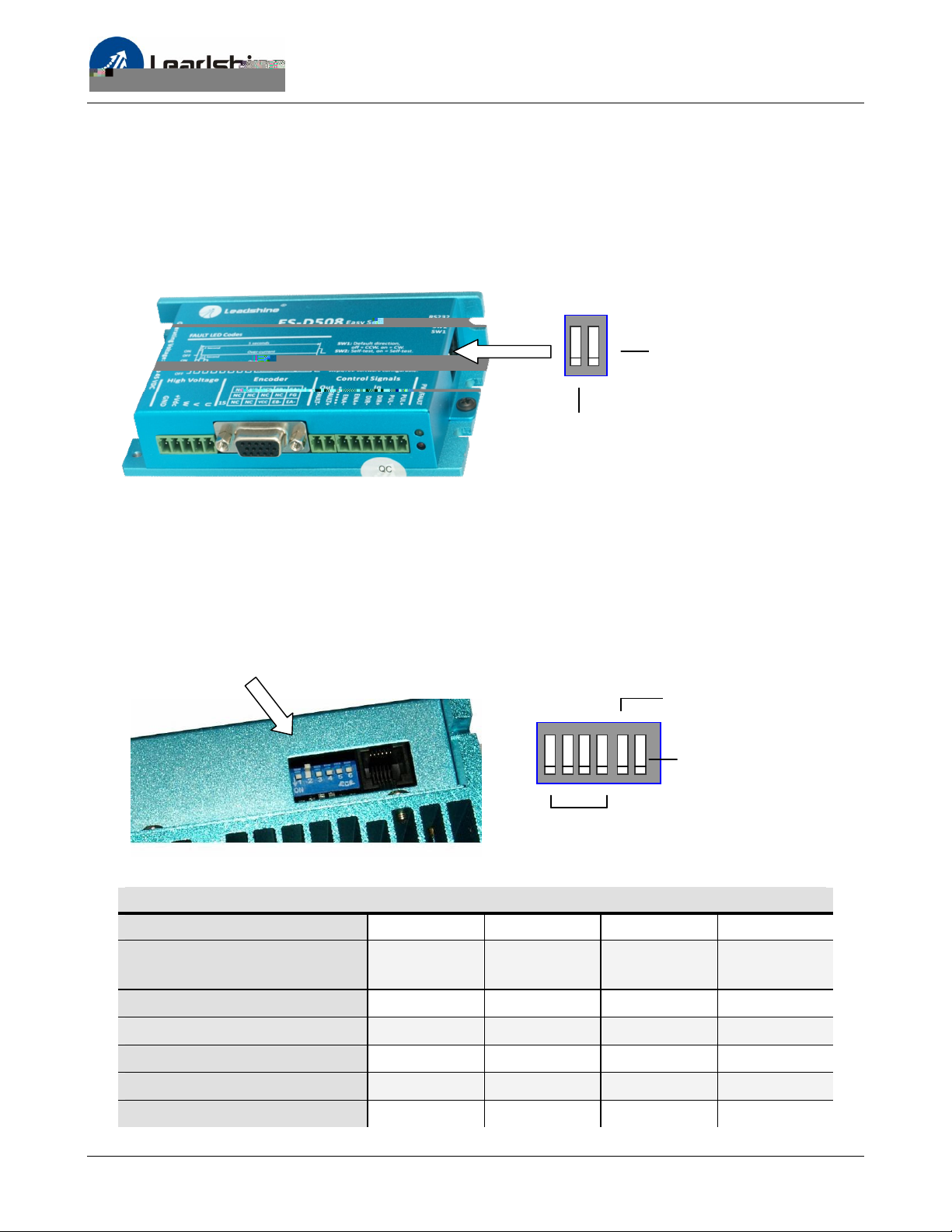
There is a 2-bit DIP switch on the ES-D508 which can be used to reverse the default motion direction
and perform motor self-test.
SW1 is used to reverse the
default motion direction.
Set SW2 on to activate
the motor self-test.
ES-D808 / ES-D1008
There is a 6-bit DIP switch on the ES-D808 or ES-D1008 drive. SW1 to SW4 are used to set the micro
step resolution and SW5 are used to set the default motion direction.
6-bit DIP switches on ES-D808 / ES-D1008
SW5 is used to reverse the
default motion direction.
Set SW6 on to activate
the motor self-test.
SW1-SW4
Microstep Resolutions
ES-D808 / ES-D1008 Resolution Settings
Steps/Revolution SW1 SW2 SW3 SW4
Software Configured
(Default 400)
800
on on on on
off on on on
1600 (Factory Setting)
3200
6400
12800
on off on on
off off on on
on on off on
off on off on
14
Page 19
Hardware Manual of the ES-D Series Drives
ES-D808 / ES-D1008 Resolution Settings (Continued)
25600
51200
1000
2000
4000
5000
8000
10000
20000
40000
on off off on
off off off on
on on on off
off on on off
on off on off
off off on off
on on off off
off on off off
on off off off
off off off off
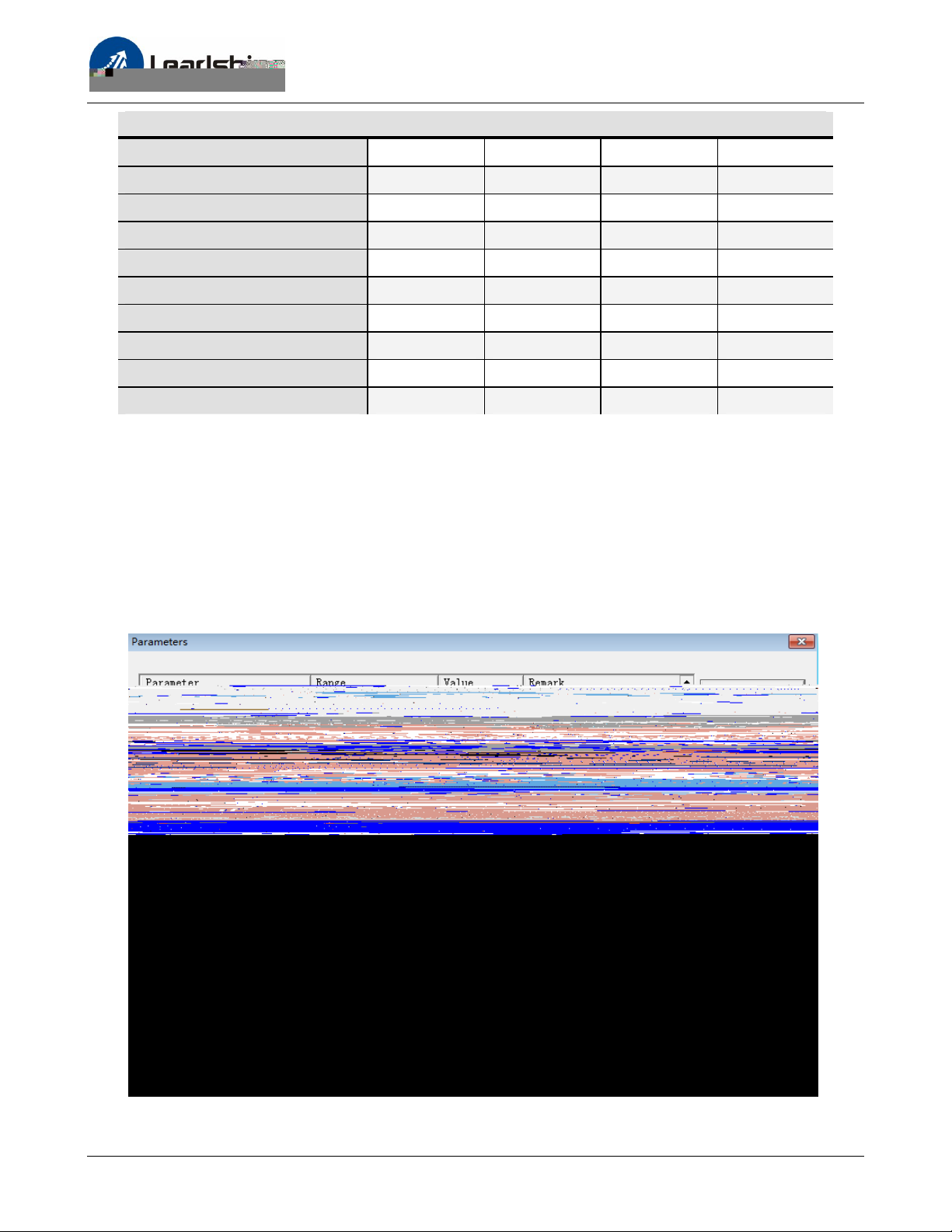
Configuring ES drive in the PC Software
Consult the “Connecting to PC Software” chapter for how to connect the easy servo drive to PC.
Suppose the tuning software has been open, click the “Drive->Parameters” to open the Parameters
window. Double click the Value column to modify the parameter. Don’t forget to click “Save” to store
the change to drive’s NVM. Consult the “Configuration” chapter for the recommended settings of
different easy servo kits. Refer to the software manual for more information about the parameters.
15
Page 20

Hardware Manual of the ES-D Series Drives
Rotating the Motor
Calculating Rotation Speed and Angle
You may also want to calculate the motor rotation speed and rotation angle, before commanding any
motion. If the pulse frequency and counts are known, they can be calculated as follows:
Rotation Speed (RPM) = 60 * Pulse (Step) Frequency / Micro Step Resolution
Rotation Angle (°) = 360 * Pulse (Step) Counts / Micro Step Resolution
Rotating the Motor by Motion Controller
You can start the controller or pulse generator to rotate the motor. Actually, any device which gives
high-to-low or low-to-high level changes can be used to move the motor. If it is your first time
installation, it is recommended to disconnect the motor shaft from the load in case of accident. You
can start from low pulse frequency then going to high. One triggered edge of the pulse makes the
motor move one micro angle. There are no minimum speed limits for the ES servos, however the
maximum running speed will be determined by the input voltage, current settings or maximum input
frequency of the drive.
Rotating the Motor in Self-test Mode
When the drive is configured in self-test mode by setting the SW2 to the ON position, the connecting
motor will rotates 1 revolution CW and 1 revolution CCW then repeat, until you set the SW2 to the
OFF position.
Rotating the Motor in PC Software
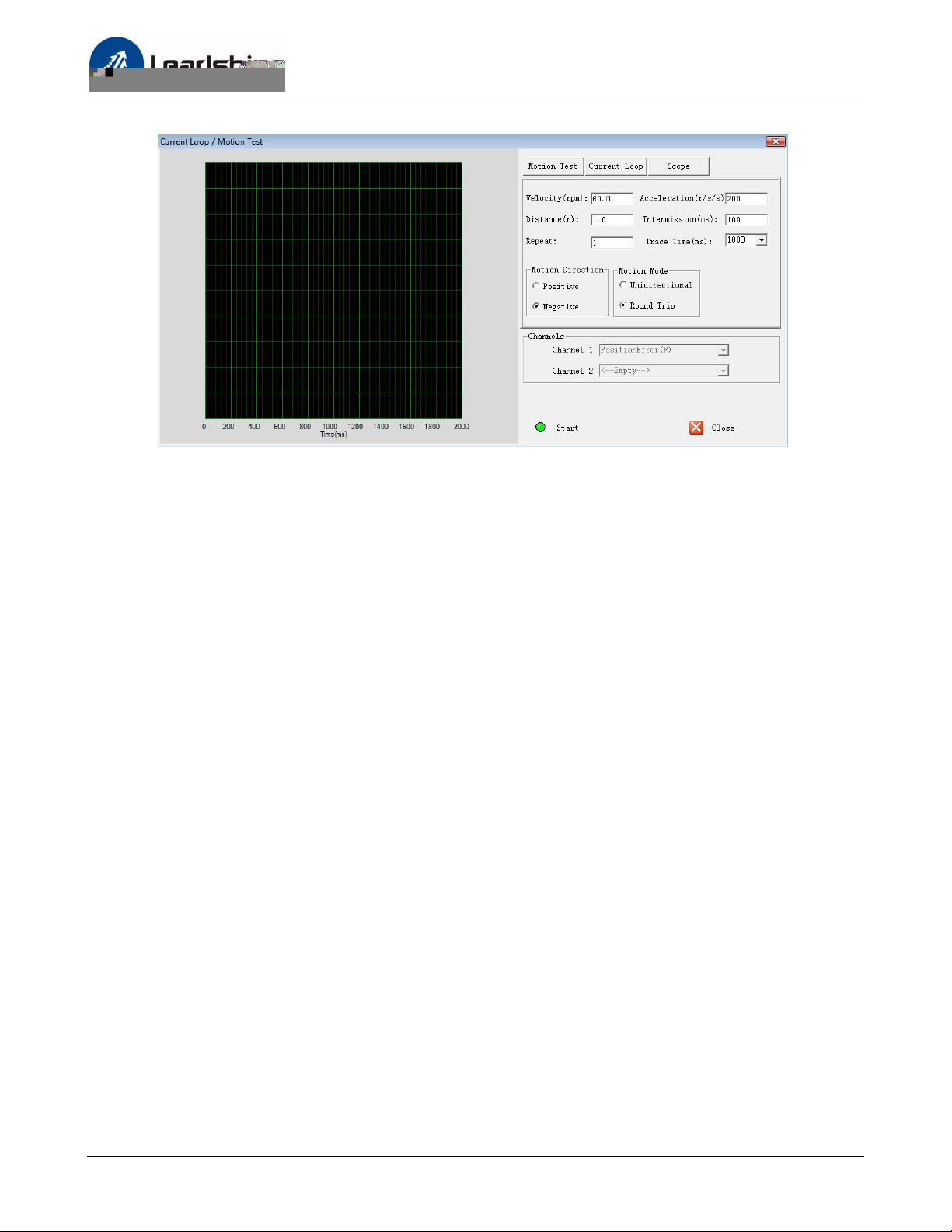
There is a simple emulating controller that is used for self-test in the ES-D drive. It is not a full
functionality controller, but it do eliminates the troubles to setup an external motion controller when
you want to test the ES drives or verify the connection in case of problem. However, the
performance in the emulating controller DOES NOT represent that of using an external motion
controller.
16
Page 21
Hardware Manual of the ES-D Series Drives
Click Drive Settings->Current Loop / Motion Test to open the test window. Then click the Motion
Test tab to open the emulating controller. Edit the trapezoidal velocity profile and click the Start
button to execute the motion.
Power Supply Selection
To achieve good driving performances, it is important to choose a suitable supply voltage and use a
matching current value. Generally speaking, supply voltage determines the high speed performance
of the motor, while output current determines the output torque of the driven motor (particularly at
lower speed). Higher supply voltage will allow higher motor speed to be achieved, at the price of
more noise and heating. If the motion speed requirement is low, it’s better to use lower supply
voltage to decrease noise, heating and improve reliability.
Regulated or Unregulated Power Supply
Both regulated and unregulated power supplies can be used to supply the drive. If regulated power
supplies (such as most switching supplies.) are indeed used, it is important to have large current
output rating to avoid problems like current clamp, for example using 4A supply for 3A motor-drive
operation. On the other hand, if unregulated supply is used, one may use a power supply of lower
current rating than that of motor (typically 50%~70% of motor current). The reason is that the drive
draws current from the power supply capacitor of the unregulated supply only during the ON
duration of the PWM cycle, but not during the OFF duration. Therefore, the average current
withdrawn from power supply is considerably less than motor current. For example, two 3A motors
can be well supplied by one power supply of 4A rating.
17
Page 22
Hardware Manual of the ES-D Series Drives
Multiple Drives
It is recommended to have multiple drives to share one power supply to reduce cost, if the supply
has enough capacity. To avoid cross interference, DO NOT daisy-chain the power supply input pins of
the drives. Instead, please connect them to power supply separately.
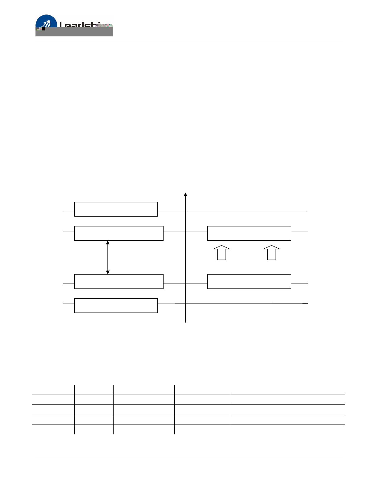
Selecting Supply Voltage
Higher supply voltage can increase motor torque at higher speeds, thus helpful for avoiding losing
steps. However, higher voltage may cause bigger motor vibration at lower speed, and it may also
cause over-voltage protection or even drive damage. Therefore, it is suggested to choose only
sufficiently high supply voltage for intended applications, and it is suggested to use power supplies
with theoretical output voltage of drive’s minimum + 10% to drive’s maximum – 10%, leaving room
for power fluctuation and back-EMF.
Drive Upper Input Limit
Drive Upper Input Limit – 10%
Safe Region
Drive Upper Input Limit + 10%
Drive Lower Input Limit
Torque & Speed Heating & Vibration
Maximum Safe Rating
Minimum Safe Rating
Drive Input Voltage Power Supply Voltage
Recommended Supply Voltage
Both Leadshine’s regulated and unregulated power supplies are specially designed for motion
control.
Motor Drive Voltage Range Typical Voltage Leadshine Power Supply
ES-M32309 ES-D508 DC(20-50)V DC 24V RPS2410
ES-M32320 ES-D508 DC(20-50)V DC 36V RPS369
ES-M23440 ES-D808 DC(30-80)V DC 60V RPS608
ES-M23480 ES-D808 DC(30-80)V DC 60V RPS608
18
Page 23
Hardware Manual of the ES-D Series Drives
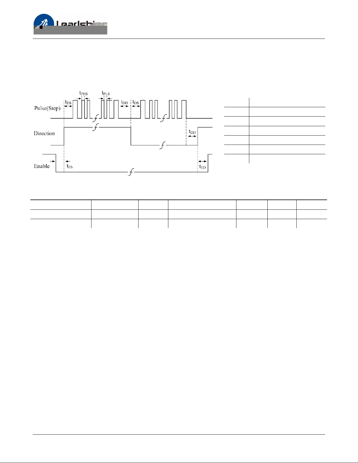
Control Signal Setup Timing
To make a reliable operation, the ES drive requires the control signals to meet the setup time
requirements as follows. Otherwise losing of steps may happen.
Symbol Description
tDS Direction Setup Time
t
Pulse High Level Setup Time
PHS
t
Pulse Low Level Setup Time
PLS
tDD Direction Delay Time
tES Enable Setup Time
tED Enable Delay Time
Control Signal Setup Time
Drive Frequency tDS t
ES-D508 200K >5uS >2.5us >5uS >50ms >50ms
ES-D808 / ES-D1008 200K >5uS >2.5us >5uS >50ms >50ms
PHS / tPLS
tDD tES tED
Current Control Detail
Leadshine’s easy servo motor is integrated with a high-resolution 1,000-line optical incremental
encoder. That encoder can send the real-time shaft position back to the ES-D drive. Like traditional
servo controls, the drive can automatically adjust the output current to the motor. The output
current ranges between the holding current and the close-loop current. When there is no pulse sent
to the drive, the ES-D drive goes into idle mode and the actual motor current is determined by the
holding current percentage (similar to “ idle current” of open loop stepper drives). In normal working
mode, the ES monitors the actual shaft position all the time. The current outputted to the motor
changes dynamically based on the tracking error between the actual position and the commanded
position.
Low holding current can reduce motor heating, however also reduces the holding torque which is
used to lock the motor shaft at standstill. It is recommended to determine the holding current by
whether or not there is big vibration at start-up and how much lock torque is required, based on your
actual applications.
19
Page 24
Hardware Manual of the ES-D Series Drives
Time(s) of Blink
Fine Tuning
Leadshine already loads default current-loop parameters and position-loop parameters. Those
default parameter values have been optimized. They should be good enough for most industrial
applications, and there is no need to tune them. However, if you want to fine tune the ES for best
performance for your applications, Leadshine also offers tuning software, ProTuner, which allows you
to adjust those current-loop and position-loop parameters (see software manual).
Protection Functions
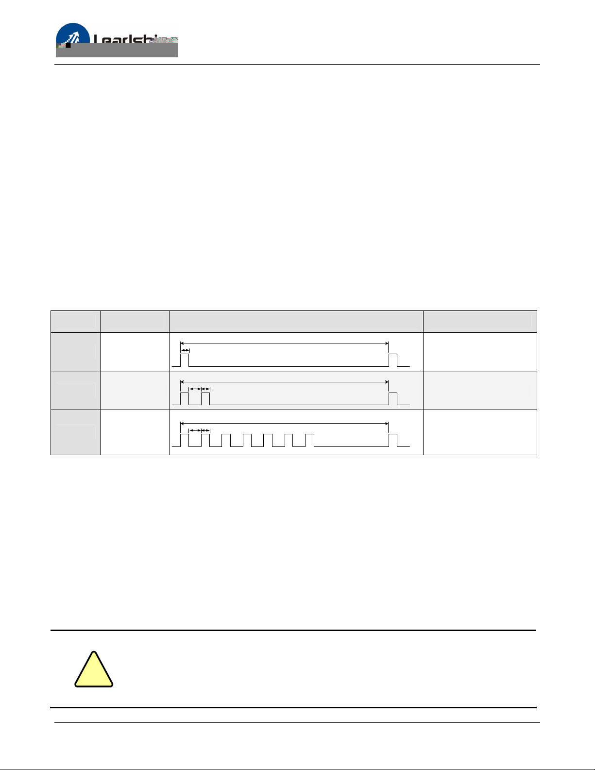
To improve reliability, the ES-D drive incorporates some built-in protection functions. The ES-D drive
uses one red LED to indicate the protection type. The periodic time is 5 s (seconds), and the blinking
times of red LED indicates what protection has been activated. Because only one protection can be
displayed by red LED, so the drive will decide what error to display according to their priorities. See
the following protection Indications table for displaying priorities.
Priority
1st
2nd
3rd
1
2
7
0.2S
0.2S
0.3S
0.2S0.3S
Sequence wave of RED LED Description
5S
Over-current protection
5S
Over-voltage protection
5S
Position Following Error
Over-current Protection
Over-current protection will be activated when continuous current exceeds the limit or in case of
short circuit between motor coils or between motor coil and ground, and RED LED will blink once
within each periodic time.
Over-voltage Protection
When input voltage including voltage fluctuation and back EMF of the motor exceeds the limits,
protection will be activated and red LED will blink twice within each periodic time.
!
Caution
When above protections are active, the motor shaft will be free and the LED will
blinks. Reset the drive by repowering it to make it function properly after
removing above problems. Since there is no protection against power leads (﹢,
﹣) reversal, it is critical to make sure that power supply leads correctly connected
to drive. Otherwise, the drive will be damaged instantly.
20
Page 25
Hardware Manual of the ES-D Series Drives
Position Following Error Protection
When the position error exceeds the limit (software configurable, see software manual), position,
protection will be activated and red LED will blink seven times within each periodic time.
Frequently Asked Questions
In the event that your drive doesn’t operate properly, the first step is to identify whether the problem
is electrical or mechanical in nature. The next step is to isolate the system component that is causing
the problem. As part of this process you may have to disconnect the individual components that
make up your system and verify that they operate independently. It is important to document each
step in the troubleshooting process. You may need this documentation to refer back to at a later date,
and these details will greatly assist our Technical Support staff in determining the problem should you
need assistance.
Many of the problems that affect motion control systems can be traced to electrical noise, controller
software errors, or mistake in wiring.
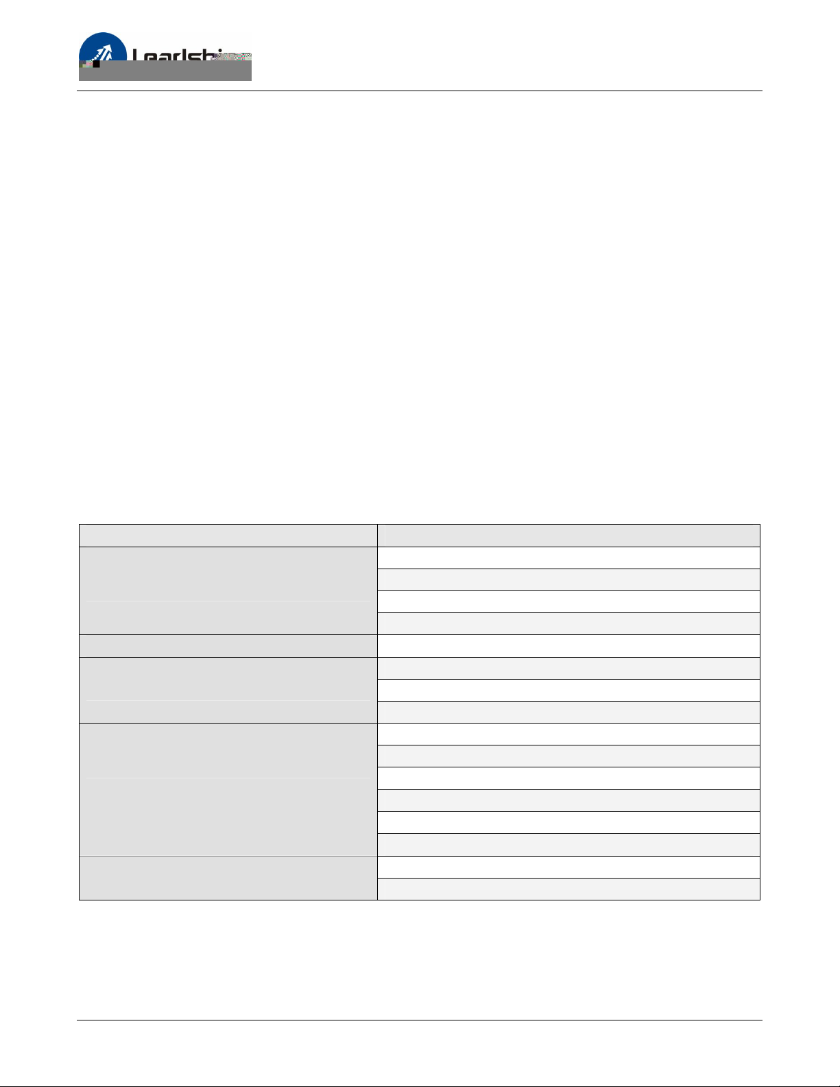
Problem Symptoms and Possible Causes
Symptoms Possible Problems
No power
Motor is not rotating
Motor rotates in the wrong direction The Direction signal level is reverse
The drive In fault
Erratic motor motion
Excessive motor and drive heating
Microstep resolution setting is wrong
Fault condition exists
The drive is disabled
Power supply voltage beyond drive’s input range
Something wrong with motor coil
Wrong connection
Control signal is too weak
Control signal is interfered
Something wrong with motor coil
Motor is undersized for the application
Acceleration is set too high
Power supply voltage too low
Inadequate heat sinking / cooling
Load is too high
21
Page 26

Hardware Manual of the ES-D Series Drives
Warranty
Leadshine Technology Co., Ltd. warrants its products against defects in materials and workmanship
for a period of 12 months from shipment out of factory. During the warranty period, Leadshine will
either, at its option, repair or replace products which proved to be defective.
Exclusions
The above warranty does not extend to any product damaged by reasons of improper or inadequate
handlings by customer, improper or inadequate customer wirings, unauthorized modification or
misuse, or operation beyond the electrical specifications of the product and/or operation beyond
environmental specifications for the product.
Obtaining Warranty Service
To obtain warranty service, a returned material authorization number (RMA) must be obtained from
customer service at e-mail: before returning product for service. Customer shall prepay shipping
charges for products returned to Leadshine for warranty service, and Leadshine shall pay for return of
products to customer.
Warranty Limitations
Leadshine makes no other warranty, either expressed or implied, with respect to the product.
Leadshine specifically disclaims the implied warranties of merchantability and fitness for a particular
purpose. Some jurisdictions do not allow limitations on how long and implied warranty lasts, so the
above limitation or exclusion may not apply to you. However, any implied warranty of
merchantability or fitness is limited to the 12-month duration of this written warranty.
Shipping Failed Product
If your product fail during the warranty period, e-mail customer service at to obtain a returned
material authorization number (RMA) before returning product for service. Please include a written
description of the problem along with contact name and address. Send failed product to distributor
in your area or: ULeadshine Technology Co., Ltd. 3/F, Block 2, Nanyou Tianan Industrial Park, Nanshan
Dist, Shenzhen, China.U Also enclose information regarding the circumstances prior to product
failure.
22
Page 27

Hardware Manual of the ES-D Series Drives
Contact Us
China Headquarters
Address: 3/F, Block 2, Nanyou Tianan Industrial Park, Nanshan District Shenzhen, China
Web: http://www.leadshine.com
Sales Hot Line:
Tel: 86-755-2641-7674 (for Asia, Australia, Africa areas)
86-755-2640-9254 (for Europe areas)
86-755-2641-7617 (for America areas)
Fax: 86-755-2640-2718
Email: [email protected].
Technical Support:
Tel: 86-755-2641-8447, 86-755-2641-8774, 86-755-2641-0546
Fax: 86-755-2640-2718
Email: [email protected](for All)
Leadshine U.S.A
Address: 25 Mauchly, Suite 318 Irvine, California 92618
Tel: 1-949-608-7270
Fax: 1-949-608-7298
Web: http://www.leadshineUSA.com
Email: [email protected] and [email protected]
23
 Loading...