

Page 1
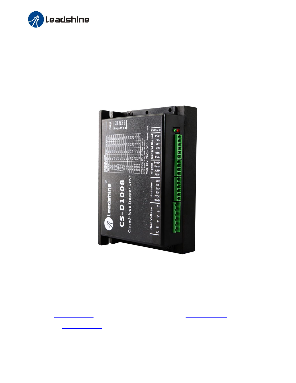
CS-D1008 Closed Loop Stepper Drive User Manual
User Manual
CS-D1008
Closed Loop Stepper Drive
Revision 1.0
© 2016 Leadshine Technology Co., Ltd.
Address: Floor 11, Block A3, Nanshan iPark, Xueyuan Avenue 1001, Shenzhen, Guangdong, 518055, China
Tel: (86)755-26409254 Fax: (86)755-26402718
Support: [email protected]
Page 2

CS-D1008 Closed Loop Stepper Drive User Manual
Revision
Date
Description of Release
1.0
September, 2017
Initial Release
Notice
Read this manual carefully before any assembling and using. Incorrect handling of products in this manual can result
in injury and damage to persons and machinery. Strictly adhere to the technical information regarding installation
requirements.
This manual is not for use or disclosure outside of Leadshine except under permission. All rights are reserved. No part
of this manual shall be reproduced, stored in retrieval form, or transmitted by any means, electronic, mechanical,
photocopying, recording, or otherwise without approval from Leadshine. While every precaution has been taken in
the preparation of the book, Leadshine assumes no responsibility for errors or omissions. Neither is any liability
assumed for damages resulting from the use of the information contained herein.
This document is proprietary information of Leadshine that is furnished for customer use ONLY. Information in this
document is subject to change without notice and does not represent a commitment on the part of Leadshine.
Therefore, information contained in this manual may be updated from time-to-time due to product improvements,
etc., and may not conform in every respect to former issues.
Record of Revisions
Page 3

CS-D1008 Closed Loop Stepper Drive User Manual
Table of Contents
1. Introduction.................................................................................................................................................................. 1
1.1 Features ................................................................................................................................................................ 1
1.2 Applications ......................................................................................................................................................... 1
2. Specifications ................................................................................................................................................................ 1
2.1 Electrical Specifications ...................................................................................................................................... 1
2.2 Environment ........................................................................................................................................................ 2
2.3 Mechanical Specifications ................................................................................................................................... 2
2.4 Heat Dissipation................................................................................................................................................... 2
3. Connections and LED Indication ............................................................................................................................... 3
3.1 Connector P1 & P2– Control Input and Output Connections .............................................................................. 3
3.1.1 Pin Assignments of P1 & P2 ..................................................................................................................... 3
3.1.2 Typical Control and Fault Output Connections ........................................................................................ 4
3.2 Connector P3 - Encoder Connection.................................................................................................................... 4
3.3 Connector P4 - Motor and Power Supply Connection ......................................................................................... 5
3.4 Connector P5 – RS232 Connection ..................................................................................................................... 5
3.5 LED Light Indication ........................................................................................................................................... 5
4. Motor Selection ............................................................................................................................................................ 5
5. Power Supply Selection ............................................................................................................................................... 5
5.1 Regulated or Unregulated Power Supply ............................................................................................................. 6
5.2 Power Supply Sharing ......................................................................................................................................... 6
5.3 Selecting Supply Voltage ..................................................................................................................................... 6
6. DIP Switch Configurations ......................................................................................................................................... 6
6.1 Microstep Resolution (SW1-SW4) ...................................................................................................................... 7
6.2 Other DIP Switch Settings (SW5-SW6) .............................................................................................................. 7
7. Typical Connection ...................................................................................................................................................... 7
8. Sequence Chart of Control Signals ............................................................................................................................ 8
9. Protection Functions .................................................................................................................................................... 9
10. Software Configuration ............................................................................................................................................. 9
11. Accessories .................................................................................................................................................................. 9
12. Troubleshooting ......................................................................................................................................................... 9
13. Warranty .................................................................................................................................................................. 11
Appendix A. Leadshine CS-D1008 Compatible Stepper Motors ............................................................................ 12
Appendix B. Leadshine CS-D1008 Compatible Power Supplies ............................................................................ 13
Page 4
CS-D1008 Closed Loop Stepper Drive User Manual
Parameters
Min
Typical
Max
Unit
Output Current
0.5
-
8.0(Peak)
A
Operating Voltage
30
48, 60, 72
100
VDC
20
63
70
VAC
Logic signal current
7
10
16
mA
Pulse input frequency
0 - 200
kHz
Minimal pulse width
2.5 - -
μS
Minimal direction setup
5.0 - -
μS
Isolation resistance
500
MΩ
1. Introduction
Leadshine CS-D1008 is a closed loop stepper drive designed to solve the loss of step problem in open loop stepper
control systems, thus increase system reliability at minimal cost increase. It implements advanced control algorithm of
Leadshine based on its tens of years’ experience in stepper and servo controls. The CS-D1008 is highly reliable and
affordable and performs excellent in many industrial applications such as CNC, medical, electronics, packaging...
The CS-D1008 can power 2-phase NEMA 34 stepper motors with incremental encoders. Compared with traditional
open loop stepper systems, a CS-D1008 adopted closed loop step system can eliminate potential loss of step, make
real-time position error correction, and do not need torque reservation (100% torque implementation). Also it can
power the driven stepper motor with reduced heating, lower noise, low vibration…
1.1 Features
No loss of step
No torque reservation
No hunting or overshooting
No tuning for easy setup
Low noise and vibration, smooth motion
20-70VAC or 30-100VDC supply voltage, max 8A output current
Max 200 KHz input frequency
15 micro step settings of 800-51,200 via DIP switches, or 200-51,200 via software (increase by 200)
Protections for over voltage, over current and position following error
1.2 Applications
When a CS-D1008 closed loop stepper drive is implemented with a compatible stepper motor with encoder, the closed
stepper system can be adopted in many small to median speed applications such as CNC routers, CNC mills, CNC
laser cutters, CNC plasmas, lab automation instruments, plotters, medical equipment, electronic equipment, small
packaging machines, etc.
2. Specifications
2.1 Electrical Specifications
Page | 1
Page 5
CS-D1008 Closed Loop Stepper Drive User Manual
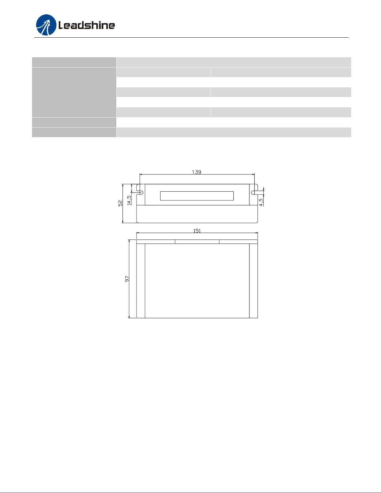
Cooling
Natural Cooling or Forced Cooling
Operating Environment
Environment
Avoid dust, oil fog and corrosive gases
Ambient Temperature
0°C - 65°C (32°F - 149°F)
Humidity
40%RH-90%RH
Operating Temperature
0°C - 50°C (32°F - 122°F)
Vibration
10-50Hz / 0.15mm
Storage Temperature
-20°C - 65°C (-4°F - 149°F)
Weight
Approx. 570 g (20.2 Oz)
2.2 Environment
2.3 Mechanical Specifications
(unit: mm [1inch=25.4mm])
2.4 Heat Dissipation
CS-D1008 reliable working temperature should be no more than 60℃ (140°F)
It is recommended to mount the drive vertically to maximize heat dissipation. Mount a cooling fan nearby if
necessary.
If multiple CS-D1008 drives are installed, it is suggested to keep a minimal 30mm (12 inches) between two of
them.
Figure 1: Mechanical specifications
Page | 2
Page 6
CS-D1008 Closed Loop Stepper Drive User Manual
Pin Name
I/O
Details
PUL+
I
Pulse signal: (1). In single pulse (pulse & direction) control mode, this input represents pulse
signal. A pulse signal is active at the rising or falling voltage edge (set by PC software). (2). In
double-pulse (CW/CCW) control mode (set by PC software), this signal input represents
clockwise (CW) pulse, and is active at both high voltage level and low voltage level. (3).
4.5-24V for voltage HIGH, 0-0.5V for voltage LOW (same for DIR and ENA signals). (4).
Pulse width should be set to 2.5μs or longer.
PUL-
I
DIR+
I
Direction signal: (1). In single pulse (step & direction) control mode, this signal’s low and high
voltage levels represent the two directions of motor rotation (e.g. clockwise and
counterclockwise). (2). In double-pulse (CW & CCW) control mode, this signal represents
counterclockwise (CCW) rotation. It is active at both voltage high level and low level. (3).
Minimal DIR signal setup time should be at least 5μs. (4). Rotation direction is related to your
motor/drive wiring. You can reverse the default rotation direction by toggling the SW5 DIP
switch.
DIR-
I
ENA+
I
Enable signal: This signal is used for enabling/disabling the drive. High voltage level of
4.5-24V (NPN control signal) for enabling the drive and low voltage level of 0-0.5VDC for
disabling the drive. PNP and Differential control signals are on the contrary, namely Low level
for enabling. By default this signal is left UNCONNECTED & ENABLED.
ENA-
I
Pend+
O
In-position Signal: OC output signal, active when the difference between the actual position and
P1
P2
P3
P4
P5
3. Connections and LED Indication
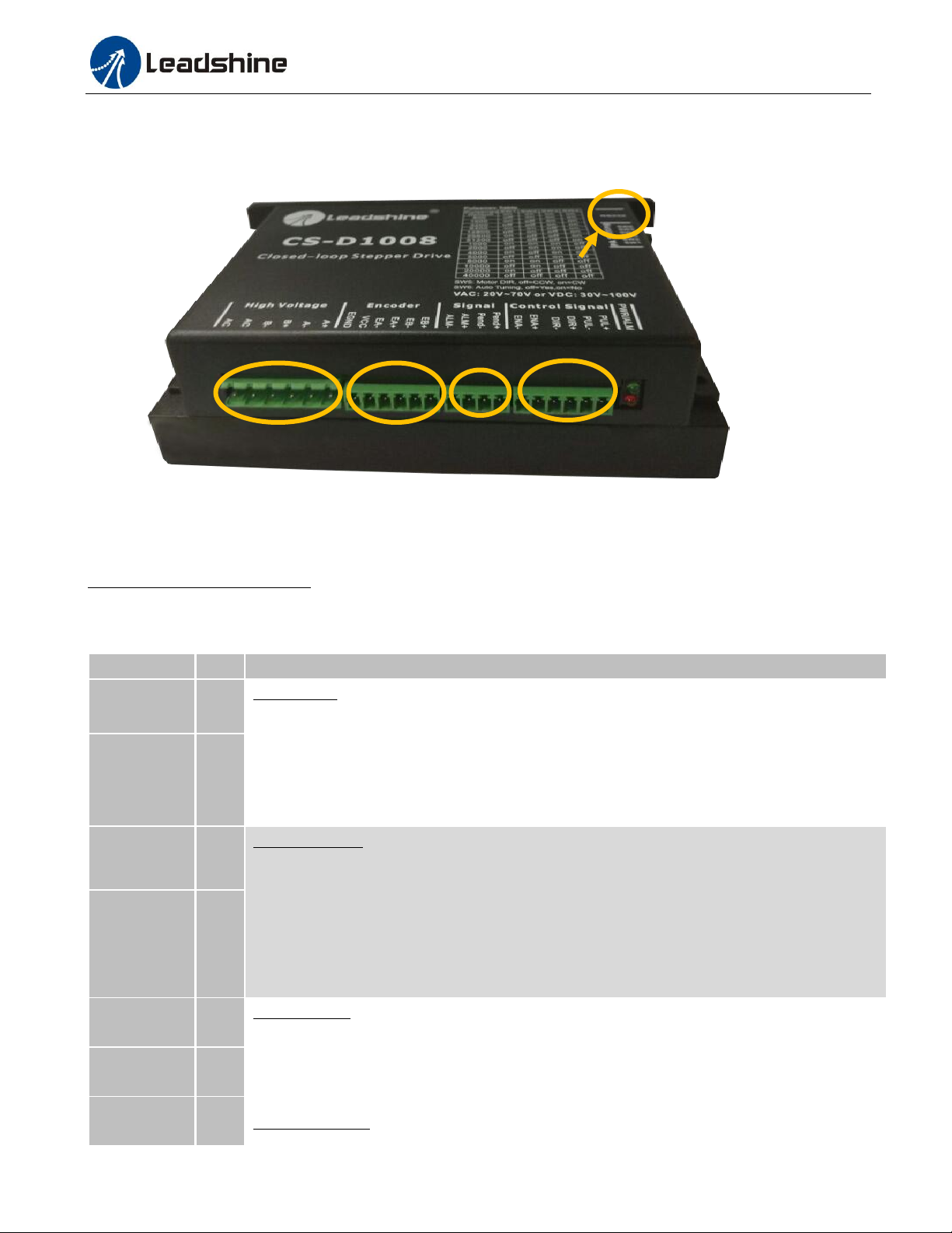
A CS-D1008 closed loop stepper drive has 5 connection blocks from P1 to P5 (see figure 2).
Figure 2: CS-D1008 connectors
3.1 Connector P1 & P2– Control Input and Output Connections
3.1.1 Pin Assignments of P1 & P2 The P1 & P2 connector in Figure 2 is for control signal and fault output connections. Refer to the following table for
details.
Page | 3
Page 7
CS-D1008 Closed Loop Stepper Drive User Manual
Pend-
O
the command position is zero. This port can sink or source 20mA current at 24V. The resistance
between Pend+ and Pend- is active at high impedance.
ALM+
O
Fault Signal: An OC output signal which is active when one of the following error protection is
activated: over-voltage, over-current, and position following error. This port can sink or source
20mA current at 24V. The resistance between ALM+ and ALM- is low impedance in normal
operation, and will change to high when the drive goes into error protection. The voltage active
level of this false output signal can be configured by configuration software.
ALM-
O
Controller
Control Signal
Connector
PUL+
1
DIR+ 3
PUL-
DIR-
2
4
ENA+ 5
ENA-
6
VCC = 5-24V
5V recommended
Step
Direction
Enable
VCC
VCC
VCC
Fault
5V
ALM+ 1
2
ALM-
Status Signal
Connector
CS-D1008
In-Positiion
Pend+ 1
2
Pend-
Controller
Control Signal
Connector
VCC = 5-24V
5V recommended
Status Signal
Connector
CS-D1008
PUL+
1
DIR+ 3
PUL-
DIR-
2
4
ENA+ 5
ENA-
6
5-24V
5V recommended
Step
Direction
Enable
Fault
5V
ALM+ 1
2
ALM-
In-Positiion
Pend+ 1
2
Pend-
Drive Pin Name
Description
EB+
Encoder B+ input connection
EB-
Encoder B- input connection
EA+
Encoder A+ input connection
EA-
Encoder A- input connection
VCC
encoder +5V voltage output connection
EGND
Power ground connection
Notes: (1) Shielding control signal wires is suggested; (2) to avoid/reduce interference, don’t tie control signal cables
and power wires together.
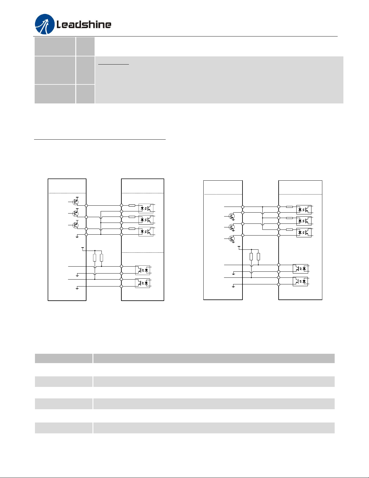
3.1.2 Typical Control and Fault Output Connections The CS-D1008 can accept differential and single-ended control signal inputs (open-collector and PNP output). A
CS-D1008 has 3 optically isolated control inputs, PUL, DIR, and ENA. Refer to the following two figures for
connections of open-collector and PNP signals.
Figure 3: Connections to PNP signal Figure 4: Connections to open-collector signal
(common-cathode) (common-anode)
3.2 Connector P3 - Encoder Connection
The P3 connector in Figure 2 is for encoder signal connection. Refer to the following table for details.
Notes: encoder resolution must be 1000-line.
Page | 4
Page 8
CS-D1008 Closed Loop Stepper Drive User Manual
Pin Name
Details
A+
Stepper motor A+ connection. Connect motor A+ wire to this pin
A-
Stepper motor A- connection. Connect motor A- wire to this pin
B-
Stepper motor B+ connection. Connect motor B+ wire to this pin
B-
Stepper motor B- connection. Connect motor B- wire to this pin
AC
Power supply connection. 30-100VDC or 20-70VAC power supply voltage
AC
RS232 Communication Port – RJ11
Pin
Name
I/O
Description
1
NC
-
Not connected.
2
+5V
O
+5V power output.
3
TxD
O
RS232 transmit.
4
GND
GND
Ground. 5 RxD
I
RS232 receive.
6
NC
-
Not connected.
3.3 Connector P4 - Motor and Power Supply Connection
The P4 connector in Figure 2 is for motor connection. Refer to the following table for details.
Notes: see Appendix B for compatible Leadshine power supplies
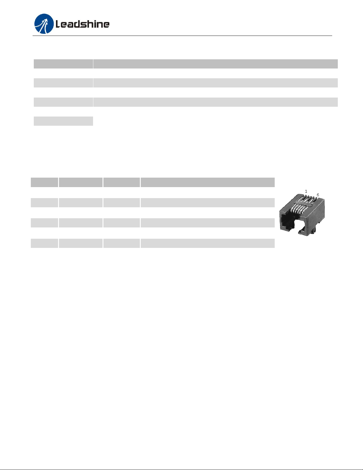
3.4 Connector P5 – RS232 Connection
The P5 connector in Figure 2 is a RS232 communication port for PC connection. Refer to the following pin definitions.
Notes: RS232 connection of CS-D1008 is for tuning purpose only, not for RS232 command controls.
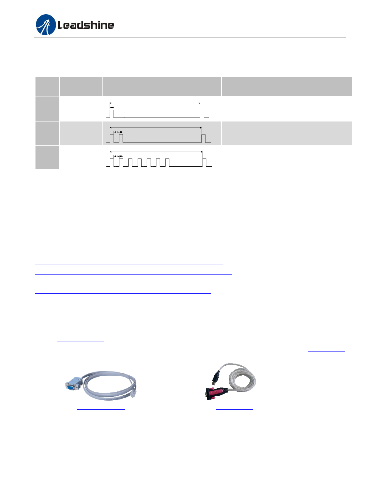
3.5 LED Light Indication
There are two LED lights for CS-D1008, one red and one green. The GREEN one is the power indicator which will be
always on generally. The RED one is a protection indicator. It is off always when a CS-D1008 operates normally, but
will flash 1, 2 or 7 times in a 5-second period when error protection is enabled. Different number of flashes indicates
different protection type (read Section 9).
4. Motor Selection
The CS-D1008 is designed to power 2-phase (or 4-phase 0.9 degree) NEMA 34 stepper motors with 1000-line
incremental encoders. Leadshine offers many high performance stepper motors compatible with the CS-D1008 which
you can find in the Appendix A of this document. The CS-D1008 can also power similar stepper motors with 1000-line
incremental encoders from third-party suppliers.
5. Power Supply Selection
The CS-D1008 can power medium size closed loop stepper motors (frame size NEMA 34) from Leadshine (see
Appendix A) or other motor manufacturers. To get good system performance, it is important to select proper supply
voltage and output current. Generally speaking, supply voltage determines the high speed performance of the motor,
Page | 5
Page 9

CS-D1008 Closed Loop Stepper Drive User Manual
while output current determines the output torque of the driven motor (particularly at lower speed). Higher supply
voltage will allow higher motor speed to be achieved, at the price of more noise and heating. If the motion speed
requirement is low, it’s better to use lower supply voltage to decrease noise, heating and improve reliability.
Notes: See Appendix B at the end of this document for Leadshine CS-D1008 compatible switching power supplies
specially designed for stepper & servo controls.
5.1 Regulated or Unregulated Power Supply
Both regulated and unregulated power supplies can be used to supply the drive. However, unregulated power supplies
are preferred due to their ability to withstand current surge and fast response for current change. If you prefer to a
regulated power supply, it is suggested to choose such a power supply specially designed for stepper/servo controls
such as Leadshine RPS series (http://www.leadshine.com/producttypes.aspx?producttype=regulated-switching). Or, in
the case when only normal switching power supplies are available, it is important to use “OVERSIZE” high current
output rating power supplies (for example, using a 4A power supply for 3A stepper motor) to avoid problems such as
current clamp. On the other hand, if unregulated supply is used, one may use a power supply of lower current rating
than that of motor (typically 50%-70% of motor current). The reason is that the drive draws current from the power
supply capacitor of the unregulated supply only during the ON duration of the PWM cycle, but not during the OFF
duration. Therefore, the average current withdrawn from power supply is considerably less than motor current. For
example, two 3A motors can be well supplied by one power supply of 4A rating.
5.2 Power Supply Sharing
Multiple CS-D1008 drives can share one power supply to save space and reduce cost, if that power supply has enough
power capacity. To avoid cross interference, connect each stepper drive directly to the shared power supply separately.
To avoid cross interference, DO NOT daisy-chain connect the power supply input pins of the Drivers. Instead connect
them to power supply separately.
5.3 Selecting Supply Voltage
The CS-D1008 is designed to operate within 20-70VAC or 30-100VDC voltage input. When selecting a power supply,
besides voltage from the power supply power line voltage fluctuation and back EMF voltage generated during motor
deceleration needs also to be taken into account. Ideally it is suggested to use a power supply with the output of
20-70VAC or 48-100VDC, leaving room for power line voltage fluctuation and back-EMF.
Higher supply voltage can increase motor torque at higher speeds, thus helpful for avoiding losing steps. However,
higher voltage may cause bigger motor vibration at lower speed, and it may also cause over-voltage protection or even
drive damage. Therefore, it is suggested to choose only sufficiently high supply voltage for intended applications.
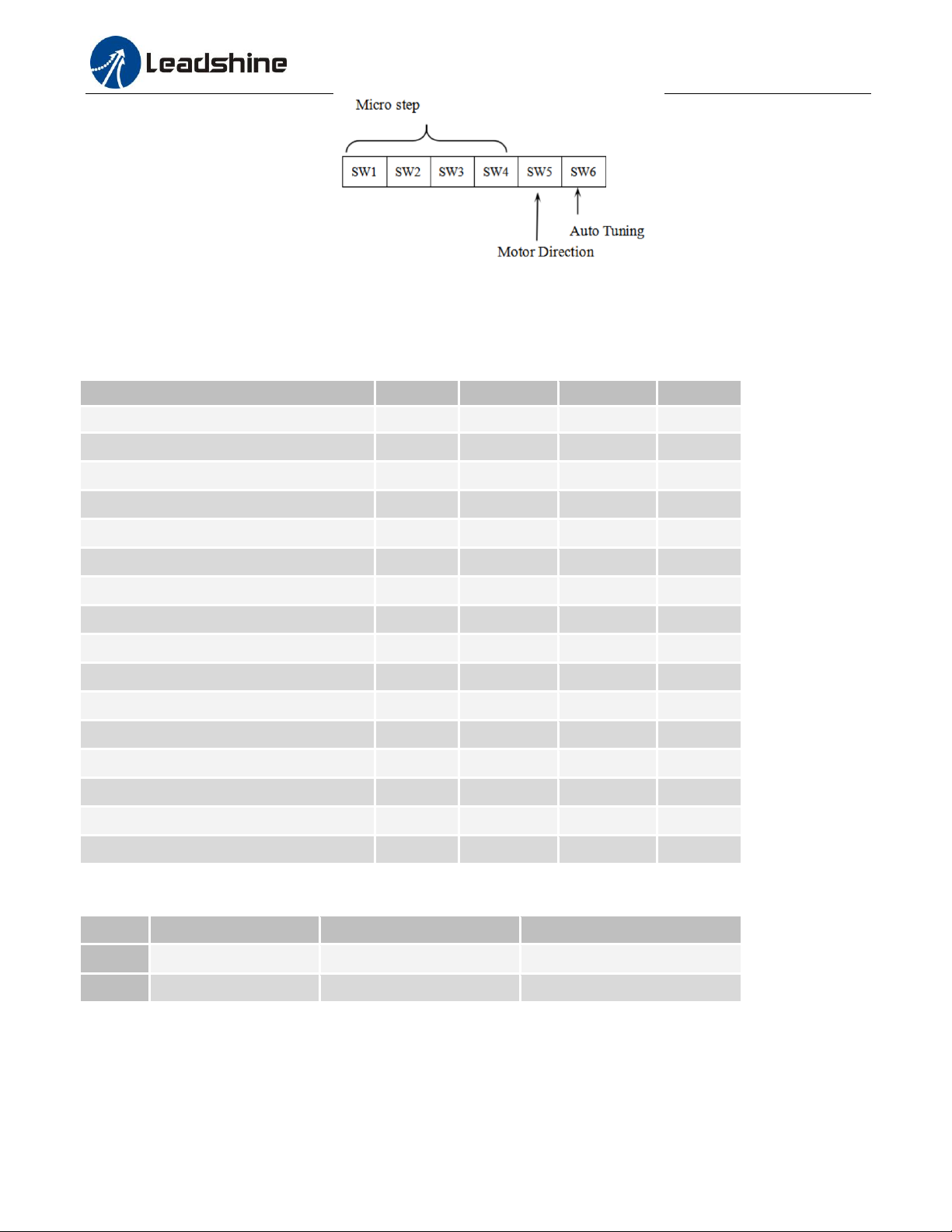
6. DIP Switch Configurations
The CS-D1008 has a built-in 8-bit DIP switch to set microstep resolution, motor direction, auto tuning switch and so
on.
Page | 6
Page 10
CS-D1008 Closed Loop Stepper Drive User Manual
Steps/Revolution
SW1
SW2
SW3
SW4
Software Configured (Defaulted to 1600)
on
on
on
on
800
off
on
on
on
1600
on
off
on
on
3200
off
off
on
on
6400
on
on
off
on
12800
off
on
off
on
25600
on
off
off
on
51200
off
off
off
on
1000
on
on
on
off
2000
off
on
on
off
4000
on
off
on
off
5000
off
off
on
off
8000
on
on
off
off
10000
off
on
off
off
20000
on
off
off
off
40000
off
off
off
off
Function
On
Off
SW5
Default Direction
CW (clockwise)
CCW (counterclockwise)
SW6
Auto Tuning
No
Yes
Figure 5 DIP switch Setting
6.1 Microstep Resolution (SW1-SW4)
Microstep resolution is set by SW1, 2, 3, 4 of the DIP switches as shown in the following table:
6.2 Other DIP Switch Settings (SW5-SW6)
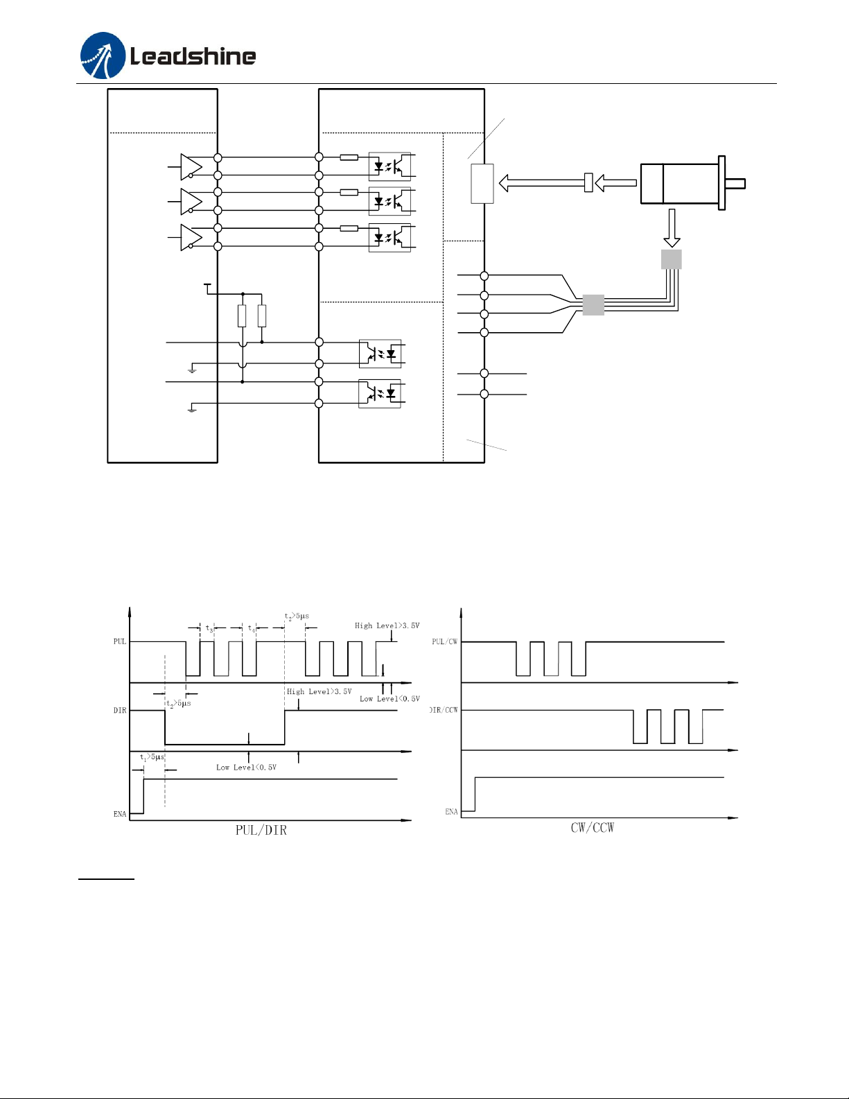
7. Typical Connection
A complete closed loop stepper system should include a stepper motor with encoder, CS-D1008 drive, power supply
and controller (pulse generator). A typical connection is illustrated in figure 6.
Page | 7
Page 11
CS-D1008 Closed Loop Stepper Drive User Manual
Vac
A+
A-
Vac
Encoder Signal
Connector
1
5
6
Power &
Motor Connector
Controller
Black
Red
Control Signal
Connector
4
PUL+
1
DIR+ 3
PUL-
DIR-
2
4
ENA+ 5
ENA-
6
5V
Step
Direction
Enable
EA+: BLK EA-: BLU
EB+: YEL EB-: GRN
+5V: RED GND: WHT
Status Signal
Connector
20-63VAC or 30-90VDC recommended,
leaving rooms for voltage fluctuation and
back EMF of the motor
2
Encoder
Extension Cable*
Encoder
Cable
*must be used
Power
Extension Cable
Power
Cable
3
B+
B-
Yellow/Green
Blue
CS-D1008
Fault
5V
ALM+ 1
2
ALM-
In-Positiion
Pend+ 1
2
Pend-
Figure 6: Typical connection
8. Sequence Chart of Control Signals
In order to avoid some fault operations and deviations, PUL, DIR and ENA should abide by some rules, shown as
following diagram:
Remark:
a) t1: ENA must be ahead of DIR by at least 5s. Usually, ENA+ and ENA- are NC (not connected). See
“Connector P1 Configurations” for more information.
Figure 7: Sequence chart of control signals
b) t2: DIR must be ahead of PUL effective edge by 5s to ensure correct direction;
c) t3: Pulse width not less than 2.5s;
d) t4: Low level width not less than 2.5s.
Page | 8
Page 12
CS-D1008 Closed Loop Stepper Drive User Manual
Priority
Time(s) of
Blink
Sequence wave of red LED
Description
1st
1
0.2S
5S
Over-current protection activated when peak
current exceeds the limit.
2nd
2
0.2S
0.3S
5S
Over-voltage protection activated when drive
working voltage is greater than 160VDC
3nd
7
0.2S
0.3S
5S
Position following error
9. Protection Functions
To improve reliability, the drive incorporates some built-in protections features.
When above protections are active, the motor shaft will be free or the red LED blinks. Reset the drive by repowering it
to make it function properly after removing above problems.
10. Software Configuration
The CS-D1008 is designed for simple setup and implementation. For most applications no software configuration or
tuning is needed especially when driving Leadshine stepper motors with encoders (see Appendix A). If you want to do
fine tuning or custom configurations such as micro-step, current percentage change…, you can use Leadshine’s free
ProTuner software to make the changes. Download ProTuner at
http://www.leadshine.com/UploadFile/Down/ProTuner_CS_Ds.V1.0.zip or
http://www.leadshineusa.com/UploadFile/Down/ProTuner_CS_Ds.V1.0.zip. Download the software manual at
http://www.leadshine.com/UploadFile/Down/CS-Dsm_V1.0.pdf or
http://www.leadshineusa.com/UploadFile/Down/CS-Dsm_V1.0.pdf.
11. Accessories
If you plan to use the ProTuner software, contact your supplier or Leadshine to purchase the RS232 cable with part
number 1.4.4-0609505-B3 for connecting the CS-D1008 to a computer with Windows XP / 7 installed. In the case of
using USB to RS232 conversion, contact your supplier or Leadshine for such a cable with part number USBToRS232
which has been verified working fine.
1.4.4-0609505-B3 USBToRS232
(RS232 tuning cable) (USB to RS232 Conversion Cable)
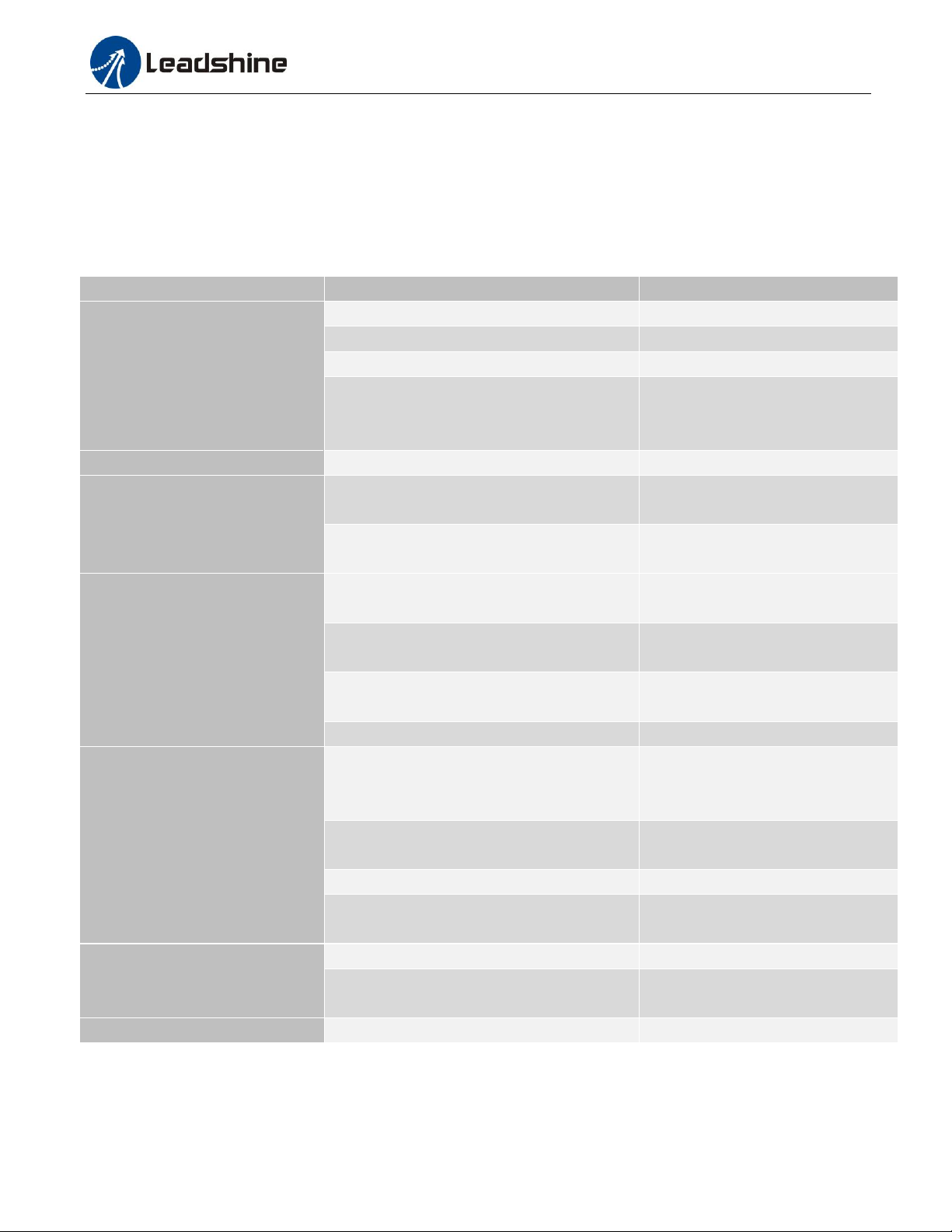
12. Troubleshooting
In the event that your drive doesn’t operate properly, the first step is to identify whether the problem is electrical or
Page | 9
Page 13
CS-D1008 Closed Loop Stepper Drive User Manual
Symptoms
Possible Problems
Solutions
Motor is not rotating
No power
Connect power supply correctly
Microstep resolution setting is wrong
Setting appropriate microstep
Fault condition exists
Check wiring and restart power
The drive is disabled
Drive restore factory setting, and
keep ENA+, ENA- input signals
unconnected.
Wrong motor rotation direction
The Direction signal level is reverse
Toggling the SW5 DIP switch
The drive in fault
Red light flashes once in a 5-second period
The motor coil may short circuit or
exiting the wrong wiring
Red light flashes twice in a 5-second period
The power supply exceeds Max.
operation voltage
Erratic motor motion
Control signal is too weak
Ensure the current of control signal
is within 7-16mA
Control signal is interfered
Don’t tie the control signal cable
with power cable together
Wrong motor connection
Refer to user manual of drive and
motor datasheet
Something wrong with motor coil
Check the motor is normal
Motor stalls during acceleration
Current setting is too small
Choose another power supply with
lager power or increase the output
current of drive
Motor is undersized for the application
Choose another motor with higher
torque
Acceleration is set too high
Reduce the acceleration
Power supply voltage too low
Choose another power supply with
large voltage output
Excessive motor & drive heating
Inadequate heat sinking / cooling
Refer to chapter 2.4
Motor peak current setting is too high
Reduce the current value refer to
motor datasheet
Motor vibration when power on
Speed loop Kp is too high
Reduce the speed loop Kp value
mechanical in nature. The next step is to isolate the system component that is causing the problem. As part of this
process you may have to disconnect the individual components that make up your system and verify that they operate
independently. It is important to document each step in the troubleshooting process. You may need this documentation
to refer back to at a later date, and these details will greatly assist our Technical Support staff in determining the
problem should you need assistance.
Many of the problems that affect motion control systems can be traced to electrical noise, controller software errors, or
mistake in wiring.
Page | 10
Page 14

CS-D1008 Closed Loop Stepper Drive User Manual
13. Warranty
Twelve Month Warranty
Leadshine Technology Co., Ltd. warrants its products against defects in materials and workmanship for a period of 12
months from shipment out of factory. During the warranty period, Leadshine will either, at its option, repair or replace
products which proved to be defective.
Exclusions
The above warranty does not extend to any product damaged by reasons of improper or inadequate handlings by
customer, improper or inadequate customer wirings, unauthorized modification or misuse, or operation beyond the
electrical specifications of the product and/or operation beyond environmental specifications for the product.
Obtaining Warranty Service
To obtain warranty service, please contact your seller to obtain a returned material authorization number (RMA) before
returning product for service.
Shipping Failed Products
If your product fail during the warranty period, please contact your seller for how and where to ship the failed product
for warranty or repair services first, you can also e-mail customer service at [email protected] to obtain a returned
material authorization number (RMA) before returning product for service. Please include a written description of the
problem along with contact name and address.
Page | 11
Page 15
CS-D1008 Closed Loop Stepper Drive User Manual
Model
Frame Size
(NEMA)
Torque
(N.m / Oz-In)
Series
Length
(mm / inch)
Notes
CS-M23435
34
3.5 / 495
CS-M
95 / 2.20
0.551-inch (14-mm) shaft
CS-M23435-S
3.5 / 495
95 / 2.48
0.50-inch (12.7-mm) shaft
CS-M23445
4.5 / 637
109 / 2.76
0.551-inch (14-mm) shaft
CS-M23445-S
4.5 / 637
109 / 3.27
0.50-inch (12.7-mm) shaft
CS-M23445B
4.5 / 637
135 / 2.44
0.551-inch (14-mm) shaft, with
24VDC brake
CS-M23480
8.0 / 1132
127 / 3.03
0.551-inch (14-mm) shaft
CS-M23480-S
8.0 / 1132
127 / 3.82
0.50-inch (12.7-mm) shaft
CS-M23480B
8.0 / 1132
173 / 3.82
0.551-inch (14-mm) shaft, with
24VDC brake
CS-M23485
8.5 / 1202
147 / 4.13
0.551-inch (14-mm) shaft
CS-M23485-S
8.5 / 1202
147 / 4.13
0.50-inch (12.7-mm) shaft
CS-M23485B
8.5 / 1202
173 / 3.46
0.551-inch (14-mm) shaft, with
24VDC brake
CS-M234120
12.0 / 1698
158 / 4.29
0.551-inch (14-mm) shaft
CS-M234120B
12.0 / 1698
184 / 4.29
0.551-inch (14-mm) shaft, with
24VDC brake
ES-M23440
4.0 / 566
ES-M
73 / 2.87
0.551-inch (14-mm) shaft
ES-M23440-S
4.0 / 566
73 / 2.87
0.50-inch (12.7-mm) shaft
ES-M23480
8.0 / 1132
93 / 3.66
0.551-inch (14-mm) shaft
ES-M23480-S
8.0 / 1132
93 / 3.66
0.50-inch (12.7-mm) shaft
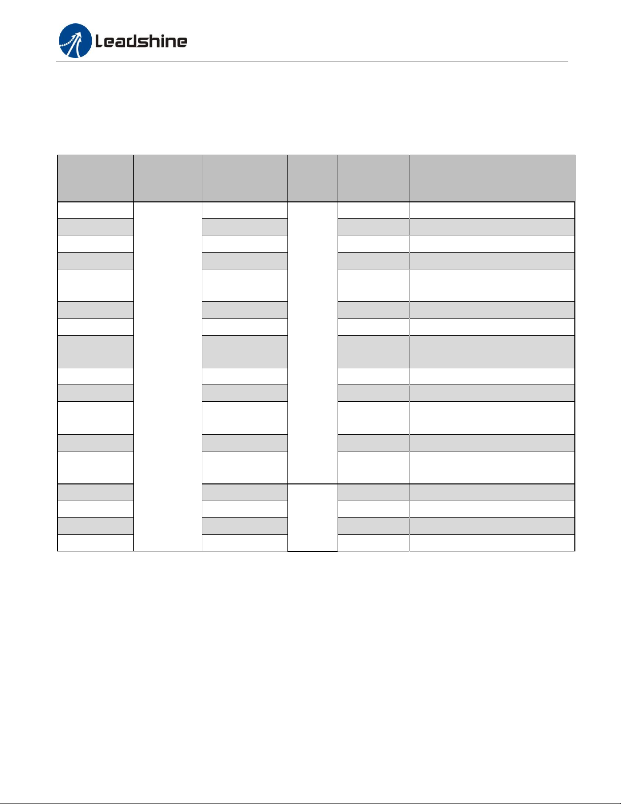
Appendix A. Leadshine CS-D1008 Compatible Stepper Motors
The following Leadshine stepper motors with 1000-line encoders have been tested working with the CS-D1008 closed
loop stepper drive.
Note: all above stepper motors are mounted with 1000-line incremental encoders
Page | 12
Page 16
CS-D1008 Closed Loop Stepper Drive User Manual
Model
Output
Voltage
(VDC)
Series
Model
Continuous
Current
(A)
Max
Current
(A)
Input Voltage
(VAC)
RPS488V20
48
RPS
8.3
24.9
85-132 / 176-264
RPS4810V20
48
10.5
31.5
85-132 / 176-264
RPS488
48
7.3
8.5
85-132 / 176-264
RPS4810
48
10.4
12.5
85-132 / 176-264
RPS608
60
8.5
10.5
85-132 / 176-264
SPS487
48
7.0
9.0
180-240
SPS487-L
48
3.0
9.0
90-130
SPS705
68
5.0
7.0
180-240
SPS705-L
68
3.0
7.0
90-130
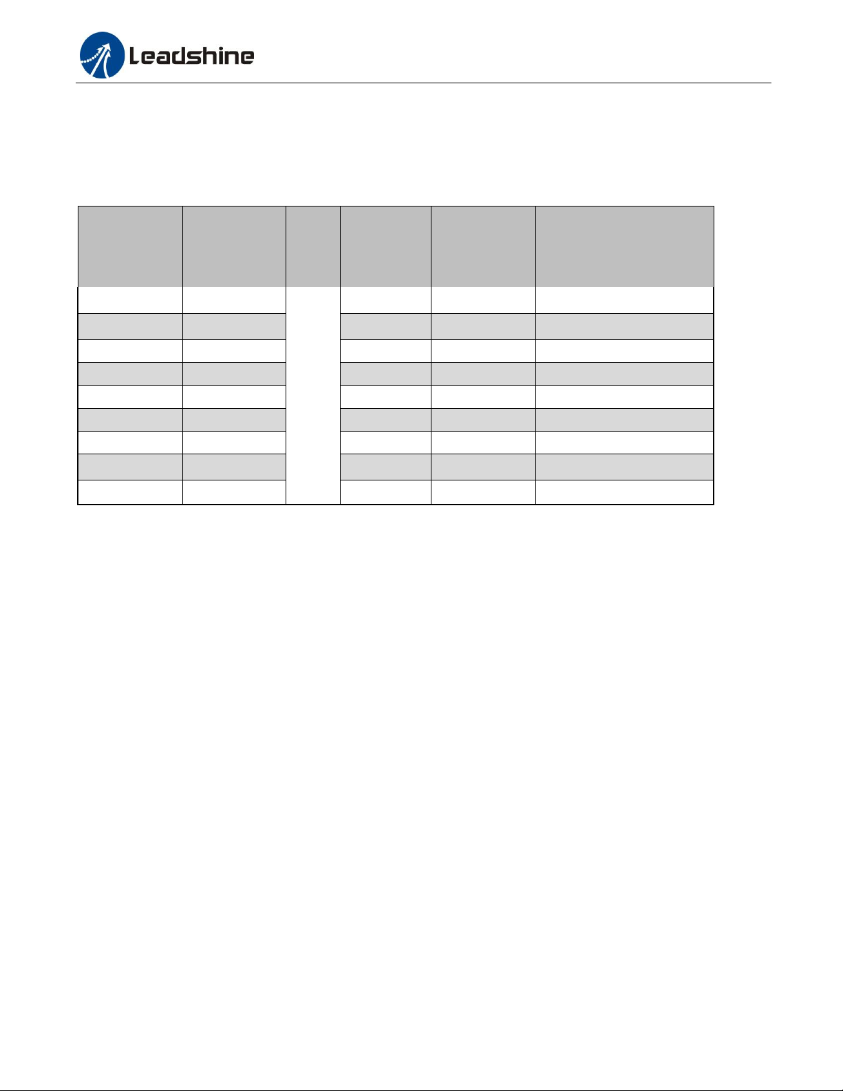
Appendix B. Leadshine CS-D1008 Compatible Power Supplies
It is highly suggested to use the following Leadshine power supplies to power CS-D1008 to get optimized performance.
Those power supply are specially designed for stepper and servo controls.
Page | 13
 Loading...