

Page 1
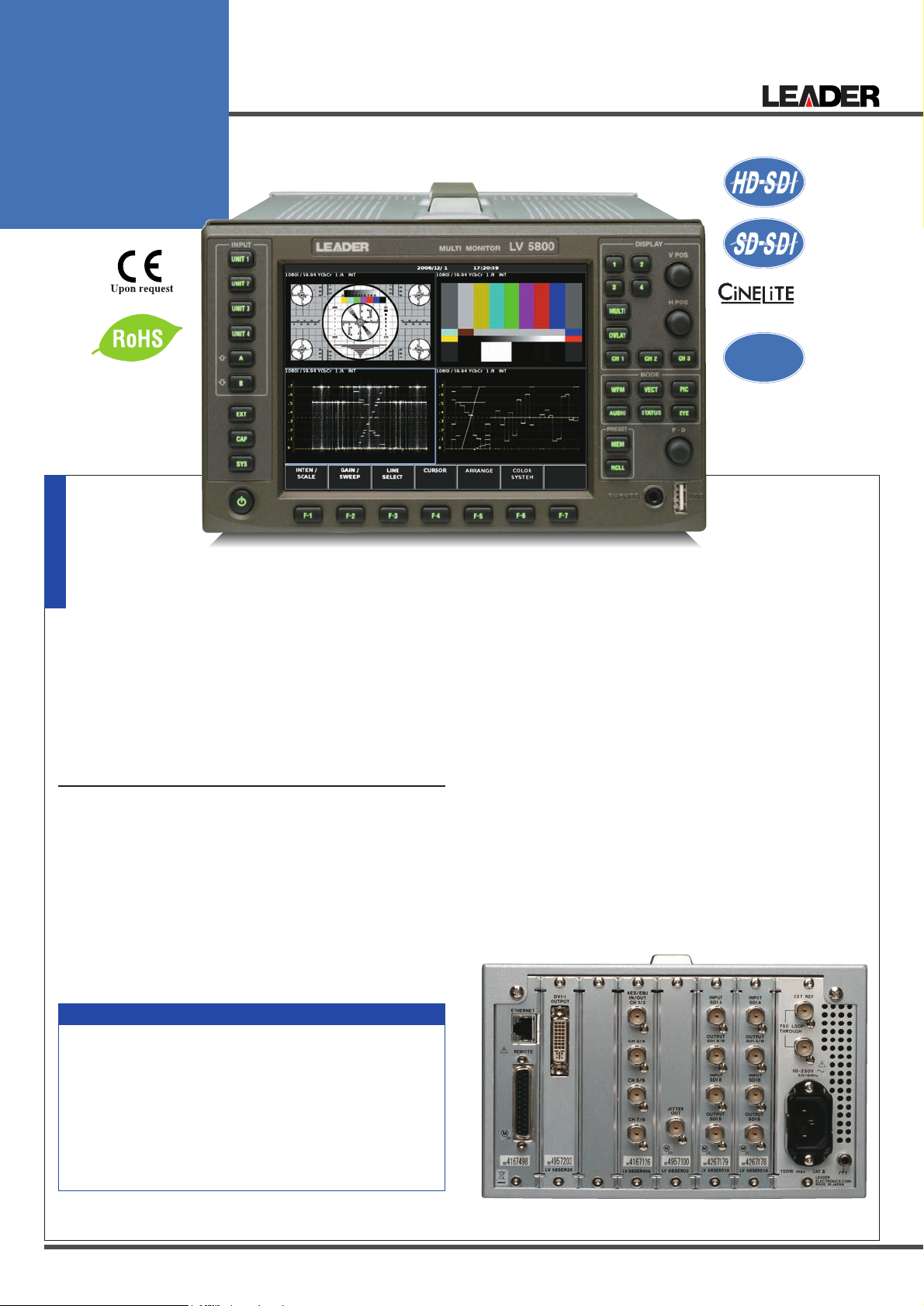
MULTI
MONITOR
LV 5800
Ⅱ
option
AFD Ready
Leader Instruments Corporation
6484 Commerce Drive
Cypress, CA 90630
www.LeaderUSA.com
Sales@LeaderUSA.com
Tel. : 1 (714) 527-9300
Fax.: 1 (714) 527-7490
Please use exclusive cabinet for Model LV 5800 (photograph shows LR 2427B)
The Panel design is subject
to change. The cabinet is
sold separately.
PATENTED:
Equivalent cable
length measurement
Your Desired combination of units allows a flexible
waveform monitor
The LV 5800 is a new type of multi monitor that allows you
freely configure various input and output units according to
your application.
You can construct a versatile system by combining dedicated
input and output units.
In particular, simultaneous display and error monitoring of
multiple SDI inputs are possible, and four-waveform parade
display on the waveform monitor is also supported.
FEATURES
Four Input Slots
•
Up to four input units can be inserted. Each input unit
operates
Two Output Slots
•
Up to two output units can be inserted. Each output unit
operates independently.
Display Function
•
Employs a color TFT LCD monitor with XGA resolution
(1,024 x 768).
The display function of each unit can be displayed on a full
screen or 4 screen multi display.
The 4 screen display allows arbitrary combination of signals
of different input units to be displayed.
independently.
Unit List
USB Connector
•
Screen captures, records of data, and presets can be
stored by connecting a USB memory to the USB connector
on the front panel.
Ethernet Connector
•
Remote control through TELNET or FTP, error monitoring,
and file transfer are possible by connecting a PC to the
Ethernet connector on the rear panel.
Remote Connector
•
The remote connector on the rear panel allows recalling of
presets, detection of errors, and switching of inputs.
Low Noise Cooling System
•
Equipped with a low noise fan. Fan speed controlled using
a temperature sensor. If the fan stops due to a malfunction,
an alarm can be displayed on the screen through the revolution sensor.
Headphone Socket
•
Sound can be monitored when the LV 58SER40A is installed.
■LV 5800 REAR PANEL
LV 58SER01A
•
LV 58SER02
•
LV 58SER03
•
LV 58SER04
•
LV 58SER20
•
LV 58SER40A
•
1
SDI INPUT
EYE PATTERN UNIT
COMPOSITE VIDEO UNIT
MPEG DECODER
DVI-I OUTPUT UNIT
DIGITAL AUDIO
LV 58SER20/LV 58SER40A/LV 58SER02/LV 58SER01A x 2 for installation example
Page 2
2
LV 5800 SPECIFICATIONS
Slot
Number of Slots for Input
Number of Slots for Output
LCD Display
LCD Screen Type
Display Format
Frame Frequency
Backlight Brightness
Auto Shutoff
Display Screen
Screen Capture
Capture
Media
Format
Data Output
Presets
Number of Presets
Media
Recall Method
Copy
External Reference Input
Input Signal
Input Connector
Input Impedance
Input Return Loss
Maximum Input Voltage
4
2
6.3-inch TFT color
XGA Effective area 1024 x 768 dots
59.94 MHz
(The input signal and the display clock signal
have not been synchronized.)
Selects HIGH or LOW
Sets the time for the backlight to shutoff automatically.
1-screen display, 2-screen display,
4-screen display
Image capture by the still picture of the display
screen
Records 1 screen in the internal memory.
Internal memory (RAM) or a USB memory
TIF, DPX
Save displayed test screens or full-frame captures in various formats, including BMP, DPX,
and TIFF. Save data to a PC via a USB memory
or Ethernet network.
60
Internal memory (RAM) or a USB memory
Through the front panel, remote connector, and
Ethernet network (Switches 8 points and 60 points
for recalling through the remote connector.)
Copies presets collectively to the USB memory
or from the USB memory to the LV 5800.
Tri-level sync signal or NTSC/PAL black burst
BNC connector 1 system 2 connectors
15 kΩ Passive Loop-through
≥30 dB
±5 V (DC + peak AC)
External Control Connector
USB Connector
Specifications
Function
Ethernet Connector
Corresponding Standard
Input/Output Connector
Function
Type
Remote Connector
Function
Control Signal
Control Connector
Headphone Output
PHONES connector
Function
Environmental Conditions
Operating Temperature
Operating Humidity
Operating Environment
Operating Altitude
Overvoltage Category
Pollution Degree
Power Requirements
Dimensions and Weight
Accessories
USB2.0
Only a large capacity memory device is supported.
IEEE802.3
RJ-45
Remote control from an external computer and
monitoring of errors, etc.
10BASE-T/100BASE-TX
Recalling of presets, monitoring of errors
LV-TTL level (LOW active)
25-pin D-sub (female)
Miniature jack (stereo)
Like LV 58SER40A (DIGITAL AUDIO), it is effective when the unit that has audio decoding function is inserted.
0 to 40 °C
≤ 85 % RH(without condensation)
Indoor use
Up to 2,000 m
II
2
90 to 250 VAC
50 Hz/60 Hz, 150 Wmax.
215(W) x 133(H) x 449(D) mm 5 kg
8 1/2(W) x 5 1/4(H) x 17 11/16(D) in 11 lbs
Power cord .......................................................1
Cover/Inlet stopper...........................................1
Screws for rack mounting
(inch specification)...........................................2
Instruction manual............................................1
25-pin D-sub connector ...................................1
25-pin D-sub connector cover .........................1
EX, LV 58SER01A 2 sets are installed EX, LV 58SER01A 2, LV58SER02
1 sets are installed
EX, LV 58SER01A 2 sets are installed EX, LV 58SER01A/LV 58SER02 1 sets
each are installed
EX, LV 58SER01A 2 set are installed
(4Y PARADE)
EX, LV 58SER01A 1 set is installed EX, LV 58SER01A 2 set are installed
EX, LV 58SER01A 2 set are installed
EX, LV 58SER01A 1 set is installed EX, LV 58SER01A 1 set is installed
EX, LV 58SER01A 1 set is installed EX, LV 58SER01A 1 set is installed EX, LV 58SER02 1, LV 58SER 01A
1 set is installed
EX, LV 58SER02 1, LV 58SER 01A
1 set is installed
EX, LV 58SER03 1 set is installed
OptionEX, LV 58SER04 1 set is installed EX, LV 58SER40A 1 set is installed EX, LV 58SER40A 1 set is installed
Multi
Wave form Vector
4 input Picture
Status Phase
V-ANC 5 Bar EyePattern/Jitter COMPOSITE
CinezoneMPEG Audio
Option
Cinelite
Leader Instruments Corporation
6484 Commerce Drive
Cypress, CA 90630
www.LeaderUSA.com
Sales@LeaderUSA.com
Tel. : 1 (714) 527-9300
Fax.: 1 (714) 527-7490
Page 3
3
LV 5800 Platform Options
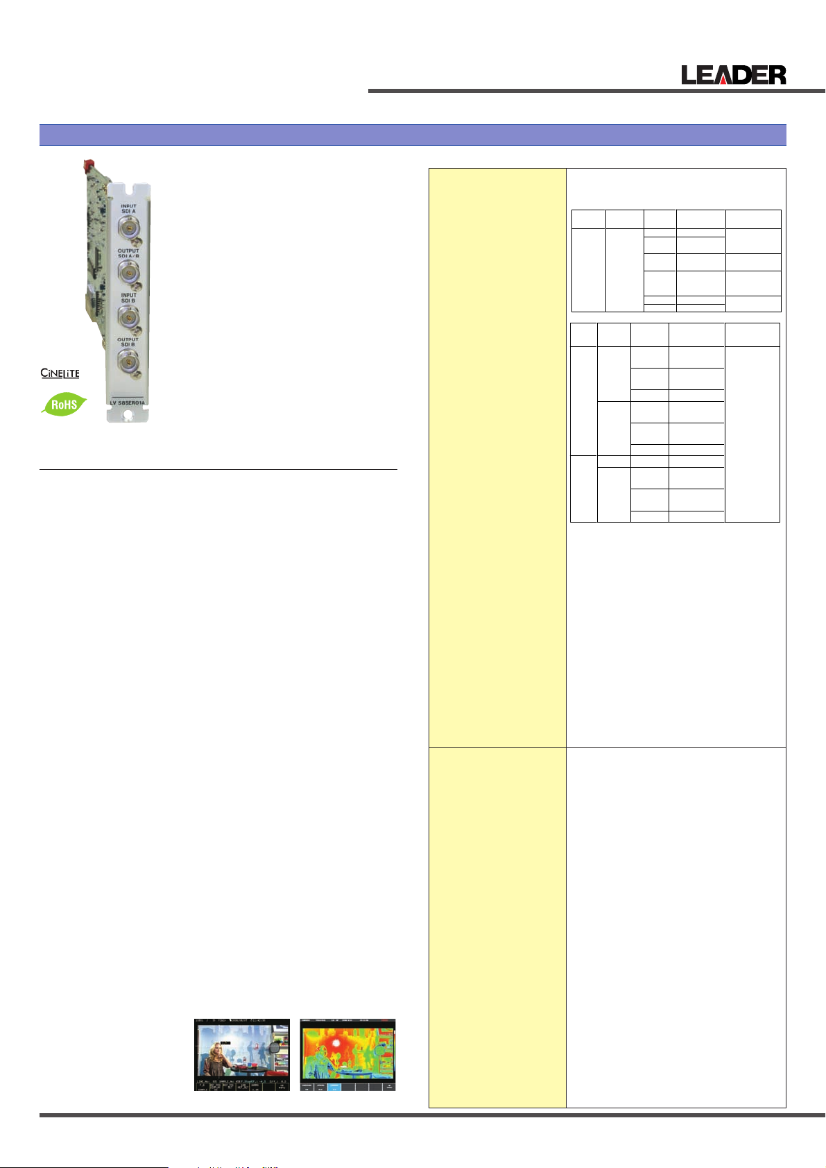
This unit is an SDI input unit that
installed in a LV 5800 input slot. The
unit allows waveform display, picture display, and error detection of
the SDI signal on the LV 5800.
Combination with other optional
units allows various displays such
as the eye pattern display of the
SDI signal (LV 58SER02) and the
Lissajous and level displays of the
embedded audio (LV 58SER40A).
The SDI signal that is inputted to
the ACH or the BCH can be outputted respectively from the
ACH/BCH Reclockout output connector by interlocking with the input
key of the front panel.
Video Formats and
Corresponding Standards
Single Link System Video
Signal Corresponding Formats
and Corresponding Standards
Dual Link System Video
Signal Corresponding
Formats and Corresponding
Standards
Ancillary data standard
Embedded audio standard
Format Setting
Input/Output Connector
SDI Input
Input Connector
Input Impedance
Input Return Loss
Maximum Input Voltage
External Sync Signal Input
Input Signal
Input Connector
SDI Output
Output Connector
Output Impedance
Output Voltage
Output Return Loss
Waveform Display Function
Waveform Operation
Display Mode
Overlay display
Parade display
Gain Adjustment
Blanking Period
YCBC
R
→
GBR conversion
Pseudo-Composite Display
Timing Display
Channel Assignment
Line Select
Image Quality Adjustment
Vertical axis
Sensitivity
Gain
Variable Gain
Amplitude Accuracy
Frequency Response HDTV
Y Signal
C
B, CR Signal
Low-pass Attenuation
Frequency Response SDTV
Y Signal
C
B, CR Signal
Low-pass Attenuation
Horizontal Axis
Line Display
Display Format
SMPTE 291M
HD-SDI: SMPTE 299M SD-SDI: SMPTE 272M
Automatic setting
BNC connector 2 connectors
For single link A ch / B ch 2 systems
For dual link link A / link B 1 system
75 Ω
15 dB or more 5 MHz to serial clock frequency
±2 V (DC + peak AC )
Tri-level sync or NTSC/PAL black burst
BNC connector 1 system 2 connectors
BNC connector 2 connectors
Reclocks serially and outputs the input signal.
For single link A ch / B ch 2 systems
For dual link link A / link B 1 system
75 Ω
800 mVp-p ±10 %
15 dB or more 5 MHz to serial clock frequency
Displays component signals overlaid
Displays component signals side by side
x1 / x5 / variable
Show / hide selectable
Converts YCBCRsignals into GBR and displays the result.
Digitally converts component signals into composite signals and displays the result.
Displays by calculating Y-C
B and Y-CR
Uses bowtie signals (authorised by Tektronix, inc.)
Selects GBR order or RGB order for the GBR conversion display
Displays the selected line
Brightness adjustment
V scale 0 V to 0.7 V, -0.3 V to 0.7 V
% scale 0 % to 100 %, -50 % to 100 %
x1, x5, and variable
x0.2 to x10
±0.5 %
±0.5 % 1 MHz to 30 MHz
±0.5 % 0.5 MHz to 15 MHz
20 dB or more at 20 MHz
±0.5 % 1 MHz to 5.75 MHz
±0.5 % 0.5 MHz to 2.75 MHz
20 dB or more at 3.8 MHz
Overlay: 1H, 2H
Parade: 1H, 2H, 3H
Timing: Y-C
B,Y-CR
4Y Parade*1: 4H
FEATURES
•
Two-Channel Serial Digital I/O
An SDI input unit contains two channels of SDI input connectors. The two connectors can also function as a dual link input
of a single channel. SDI output that is reclocked using a serial
signal is provided for each input. In addition, the SDI signal
that is inputted to the ACH or the BCH can be outputted
respectively from the ACH/BCH Reclockout output connector
by interlocking with the input key of the front panel.
•
Video Signal Display Function
In addition to displaying the video waveforms, vectors, and pictures of the SDI signal on a full screen, 2- and 4-screen multi
display can be shown. The multi display allows arbitrary combination of a single or multiple input signals to be displayed.
(Multi display in which link A and link B are separated during
dual link operation is not allowed.)
•
Error Detection Function
Detects various errors related to the SDI, embedded audio,
and ancillary data including CRC errors and EDH errors.
•
Ancillary Data Analysis
Supports various types of ancillary data for analysis display.
In particular.
•
5 BAR DISPLAY
Peak levels of video signals can be displayed in place of the
vectors.
•
SDI-EXT REF Phase Difference Display Function
The SDI-EXT REF phase difference display function shows
the phase difference between the SDI signal and the external
sync signal (EXT REF).
•
Simultaneous Monitoring of Component and Composite
Gamut Using the 5 Bar Displays
•
Japanese Caption Display Function (to be supported in
the future)
•
Embedded Audio Demultiplex Function
The unit is equipped with a function for demultiplexing the
embedded audio signal.
Level meter and Lissajous displays can be achieved when
used in combination with the digital audio unit (LV 58SER40A).
The signal can also be output as AES/EBU.
•
Dual link input
■
OPTION
•
FS 3033 Cinelite II
(Cinelite and Cinezone)
Format
Y, CB,C
R
4:2:2
Quantization
10bit
Scanning
1080i
1080p
1080PsF
720p
525
625
Standard
Supported
SMPTE 274M
SMPTE 292M
SMPTE
RP211
SMPTE 292M
SMPTE 296M
SMPTE 292M
SMPTE 259M
Frame(Field)
Frequency
60/59.94/50
30/29.97/25/
24/23.98
30/29.97/25/
24/23.98
60/59.94/50/
30/29.97/25/
24/23.98
59.94
50
Scanning
1080p
1080PsF
1080i
1080p
1080PsF
1080i
1080p
1080p
1080PsF
1080i
Quantization
10 bit
12 bit
10 bit
12 bit
Format
GBR
4:4:4
Y, CB,CR
4:2:2
Frame(Field)
Frequency
30/29.97/25/
24/23.98
30/29.97/25/
24/23.98
60/59.94/50
30/29.97/25/
24/23.98
30/29.97/25/
24/23.98
60/59.94/50
60/59.94/50
30/29.97/25/
24/23.98
30/29.97/25/
24/23.98
60/59.94/50
Standard
Supported
SMPTE 372M
(1920x1080)
LV 58SER01A SDI INPUT SPECIFICATIONS
Ⅱ
option
Cinelite Cinezone
LV 58SER01A SDI INPUT
Plug-In Unit for LV 5800
Leader Instruments Corporation
6484 Commerce Drive
Cypress, CA 90630
www.LeaderUSA.com
Sales@LeaderUSA.com
Tel. : 1 (714) 527-9300
Fax.: 1 (714) 527-7490
Page 4

4
Magnification
Field Display
Display Format
Time Base Accuracy
Cursor Measurement
Configuration
Amplitude Measurement
Time Measurement
Frequency Display
Vectorscope Display
Scale
Gain
Variable gain
Amplitude Accuracy
IQ Axis
Pseudo-Composite Display
Image Quality Adjustment
Phase Difference Display
Display
Display Range
Sync Signal
Phase Difference Measurement
of Dual Link(future support)
Picture Display
HDTV Display
SDTV Display
Marker Display
Gamut Error Display
Line Select
Image Quality Adjustment
Status Display
Status Display of SDI Signal
Signal Detection
Format
Equivalent Cable
Length Measurement
Embedded Audio Channel
Error Detection of SDI signals
CRC Error
EDH Error
TRS Error
Line Number Error
Illegal Code Error
Embedded Prohibition Error
Cable Length Meter Error
Error Detection of Embedded Audio
BCH Error
DBN Error
Parity Error
Error Detection of Ancillary Data
Checksum Error
Parity Error
Image Evaluation
Gamut Error
Composite Gamut Error
Level Error
Freeze Detection
Black Detection
Event Log
Number of Logs
5 Bar Display
Bar Display
Analysis Function
Data Dump Display
Display Format
Line Select
Sample Select
Jump Function
Data Output
Audio Control Packets
Display Content
Group Selection
EDH Display
Standard Supported
Display Content
Format ID Display
Standard Supported
Display Content
Closed Caption Data Display
Standard Supported
Display Content
Inter-Stationary Control
Data (NET-Q) Display
Standard Supported
Display Content
Log Function
V-ANC User Data Display
Standard Supported
Arbitrary ANC Packet Display
Method of Specifying ANC
Time Code Display
Corresponding Time Code
Display Method
Embedded Audio Processing
Clock Generation System
Closed Caption Processing
(future support)
SMPTE System
Cable Length Measurement
Detection method
Supported Cables
Display Range
Accuracy
Resolution
Frame Capture Function
Media
Internal Memory Capacity
Data Output
Recalling Capture Data
Power Consumption
Weight
Accessory
Selects x1, x10, x20, ACTIVE, or BLANK
*1 As for 4Y parade mode, two LV 58SER01A (SDI
INPUT unit) should be inserted, and four inputs
need to synchronize in the same format each
other together.
Overlay: 1V, 2V
(2V display not allowed for progressive)
Parade: 1V, 2V, 3V
Magnification: x1, x20, x40
±0.5 %
Horizontal cursors: 2 cursors (REF and DELTA)
Vertical cursors: 2 cursors (REF and DELTA)
Measured in [%] and [V]
Displayed in [usec] or [msec]
Displays the frequency in which the time between
cursors is considered a cycle.
Selects 75 % or 100 % (Using a color bar)
Selects x1, x5, IQ-MAG or variable
x0.2 to x10
±0.5 %
Selects show or hide
Digitally converts component signals into composite signals and displays the result. (the color matrix
for HDTV signal is converted into SDTV)
Brightness adjustment
Displays the phase difference between the SDI signal
and external sync signal numerically and graphically
Holds and displays eight phase difference values being
measured
V direction ±1/2 Frame
H direction ±1 Line
*The phase difference display in the H direction
may fluctuate in the range of ±1 clock when the
signal is switched.
HD tri-level sync or black burst signal
Displays phase difference between Link A and B
with the number of the parallel reclock. (including
±1 clock error)
Displayed by sampling the pixels (8 bit RGB)
Displayed by interpolating pixels (8 bit RGB)
Center marker
4:3 or 16:9 marker display
Safe action marker display
Safe title marker display
On picture indication of gamut errors
Displays the selected line as a marker
GBR gain adjustment, Contrast adjustment,
Brightness adjustment
Detects the presence or absence of SDI signals.
Auto format Detection
Converts the SDI signal attenuation into a coaxial
cable length and displays the result.
Displays the embedded audio channel number.
Detects transmission error of HD-SDI signals.
Detects transmission error of SD-SDI signals.
Detects errors in the TRS position and protection bit.
Line number errors in the HD-SDI signals are
being detected.
Detects data in the range of 000h to 003h and
3FCh to 3FFh outside the TRS or ADF header.
Detects the presence or absence of embedded
audio at the embedded prohibition line.
Detects the signal attenuation and displays the result.
Detects transmission errors of embedded audio
packets in the HD-SDI signal.
Detects sequential errors in audio packets.
Detects parity errors in audio packets embedded
in HD-SDI dignals
Detects transmission errors in the ancillary data.
Detects parity errors in the ancillary data header.
Detects Gamut Errors by specifying duration and size.
Upper limit: 90.8 % to 109.4 % (0.1 % steps)
Lower limit: -7.2 % to +6.1 % (0.1 % steps)
Monitors the level error when the component signal is converted into composite signal
Upper limit: 90.0 % to 135.0 % (0.1 % steps)
Lower limit: -40.0 % to 20.0 % (0.1 % steps)
Detects Y C
B CR level errors
Y upper limit: -51 mV to 766 mV (1-mV resolution)
Y lower limit: -51 mV to 766 mV (1-mV resolution)
CBCRupper limit: -400 mV to 399 mV (1-mV resolution)
C
BCR
lower limit: -400 mV to 399 mV (1-mV resolution)
Detects video freeze
Detects blackouts of the video signal
Error items, time stamps, etc.
Displays the Y GBR component Gamut and composite Gamut
Displayed by serial data sequence or channel
separation.
Displays the selected line
Displays the selected sample
Move to EAV or SAV by one-key operation
Save data in text format to a PC via or Ethernet or
USB memory.
Analyzes and displays the audio control packets
One group is selected from four groups.
SMPTE RP-165
Analyzes and displays the EDH packets.
Displays the received CRC errors.
SMPTE 352M ARIB STD-B39
Analyzes and displays the Format ID.
ARIB STD-B37,EIA/CEA-608,EIA-708
Analyzes and displays the closed caption data.
ARIB STD-B39
Analyzes and displays the Inter-Stationary Control Data.
Logs Q signals
ARIB TR-B23
Selects DID or SDID
Selects LTC or VITC SMPTE RP-188
Switches the display of internal clock, and the time
code.
SD-SDI: Generated from the video clock
HD-SDI: Generated from the video clock
Dual link (future support): Generated from the
video clock
The closed caption data that is multiplexed in the
SDI signal can be overlaid on the picture display.
CEA/EIA-608-B embedded in the CDP packets as
defined in CEA/EIA-708-B.
CEA/EIA-608-B
VBI(CEA/EIA-608-B Line21)
Converts the SDI signal attenuation into a coaxial
cable length and displays the result.
HD-SDI: Selects L-7CHD, LS-5CFB, or 1694A
SD-SDI: Selects LS-5C2V, 8281, or 1505A
HD-SDI: From under 5 m to 130 m or more
(For L-7CHD: From under 10 m to 200 m or more)
*
Less than 10 m to greater than or equal to 200 m for L-7CHD
SD-SD: From under 50 m to 300 m or more
±20 m
5 m (For L-7CHD: 10 m)
Internal memory (RAM) or USB memory
Video data 1 Frame 2 Systems
For Dual Link mode: 1 Frame 1 system
Save capture data to a PC via Ethernet network
or a
USB memory.
Recalls and displays the Picture/ Waveform/ Vector
of 1 frame capture data.
The capture data saved in the USB memory can
be read back.
(
Reading back operation is possible only if an SDI input
of the same format as the captured data is available
)
Supplied from LV 5800
70 Wmax. (If one unit is installed to the LV 5800)
18 Wmax. (additional power consumption for each
additional unit installed to the LV 5800)
0.28 kg, 0.6 lbs
Instruction manual ................................................1
Precautions Concerning Dual Link Operation
Aliasing occurs in the V sweep display of 1080p/60, 59.94, and 50, because
the unit processes the sampling data. The picture display is processed using
8 bits even if the quantization is set to 12 bits.
In addition, waveform display in external synchronization mode is not allowed
if 1080p/60 (59.94) or 1080p/50 signal is applied.
Leader Instruments Corporation
6484 Commerce Drive
Cypress, CA 90630
www.LeaderUSA.com
Sales@LeaderUSA.com
Tel. : 1 (714) 527-9300
Fax.: 1 (714) 527-7490
Page 5

5
LV 5800 Platform Options
LV 58SER02 EYE PATTERN UNIT
Plug-In Unit for LV 5800
LV 58SER03 COMPOSITE VIDEO INPUT UNIT
Plug-In Unit for LV 5800
This unit displays eye patterns. It
is installed in a LV 5800 input slot.
By combining with the LV 5800
input unit, eye pattern waveforms
of SDI signals can be monitored.
Automatic measurement of parameters such as amplitude, rise
time, and fall time is also possible.
FEATURES
•
HD-SDI, SD-SDI Format Support
•
6 Systems of Eye Pattern Displays and
Jitter Measurement
Displays the SDI signal eye pattern or measures the jitter of
one system among up to 6 systems by combining 3 SDI
input units and selecting A or B among the three modules.
(Two Eye units cannot be installed simultaneously.)
•
Eye Pattern Display
Displays the eye pattern of the timing jitter or alignment jitter
by switching the filter.
•
Jitter Measurement
The jitter measurement by the phase detection method
allows accurate jitter measurement even if the eye is barely
open. In addition, timing jitter and alignment jitter can be
measured.
•
Automatic Measurement
The eye pattern display allows automatic measurement of
the eye pattern amplitude, rise time, and fall time. The jitter
display allows automatic measurement of the timing jitter and
alignment jitter values.
•
Jitter Display Using Video Sweep
Allows V sweep and H sweep displays.
•
Simultaneous Display on the Multi Display
The multi display allows the eye pattern waveform and jitter
waveform to be displayed simultaneously. In addition, the
eye pattern display screen automatically measures the eye
pattern amplitude, rise time, and fall time, while the jitter display screen automatically measures the timing jitter and
alignment jitter.
•
Alarm Monitoring
The alarm monitor mode allows the eye pattern amplitude,
rise time, and fall time to be monitored with respect to the
threshold level specified in advance. It also monitors the timing jitter and alignment jitter using the phase detection
method. An alarm is displayed when the threshold level is
exceeded. The alarm can also be logged.
Supported Formats
Data Rate
HD-SDI
SD-SDI
Eye Pattern
Method
Amplitude Accuracy
Time Axis
Time Axis Accuracy
Jitter Filter
Jitter Detection
Method
Time Axis
Time Axis Accuracy
Jitter Filter
Power Consumption
Weight
Accessories
LV 58SER02 EYE PATTERN UNIT SPECIFICATIONS
SMPTE292M 1.485 Gbps, or 1.485/1.001 Gbps
SMPTE259M 270 Mbps
Equivalent time sampling method
800 mV ±5 % for 800 mV input
2 / 4 / 16 Eye pattern Display
±3 %
10 Hz HPF
100 Hz HPF
1 kHz HPF
100 kHz HPF
Phase detection method
H rate or V rate
±3 %
10 Hz HPF
100 Hz HPF
1 kHz HPF
100 kHz HPF
(* Doesn't support JITTER measurement of a DVBASI standard Eye pattern only.)
Supplied from LV 5800
20 Wmax.
0.4 kg, 0.9 lbs
Coaxial cable .........................................................1
Instruction manual..................................................1
The LV 58SER03 provides the
LV 5800 with two composite
(NTSC/ PAL) inputs. The LV
5800's newest functions related to
waveforms such as the waveform
monitor, vectorscope, and simple
picture monitor can be used on
analog video signals of NTSC and
PAL formats.
For a description of the specifications other than those of this
newly added option, see the
specifications of the standard
model.
This unit in combination with the
LV 58SER01A is suitable for monitoring in a mixed environment
containing SDI and composite
signals.
FEATURES
•
Input/Output
There are two input connectors: INPUT A and INPUT B.
The selected channel is output from the PIX OUT connector
on the rear panel.
•
Display
Waveform display, vectorscope display, picture display, and
EXT REF phase display function are available.
In addition, the luminance component can be displayed
using a low-pass filter.
•
SCH Measurement Function
You can perform SCH measurements which are essential
when editing the composite signal.
•
EXT REF Phase Display Function
Compares the input signal to the V.H sync signal of the
external reference signal and displays the phase difference
numerically and graphically.
This function makes synchronization phase management easy.
•
Miscellaneous
Cursors can be used to measure the amplitude and time,
with high accuracy.
Leader Instruments Corporation
6484 Commerce Drive
Cypress, CA 90630
www.LeaderUSA.com
Sales@LeaderUSA.com
Tel. : 1 (714) 527-9300
Fax.: 1 (714) 527-7490
Page 6

6
LV 58SER04 MPEG DECODER
Plug-In Unit for LV 5800
Measured Signal
Supported Standards
Input
Composite Video
Input Connector
Input Impedance
Input Return Loss
Maximum Input Voltage
Output
Composite Video
Output Signal
Output Connector
Output Impedance
Output Amplitude
Frequency Characteristics
Display
WAVE Display
VECTOR Display
PICTURE Display
Waveform Display Section
Vertical Axis
Sensitivity
Gain
Variable Gain
Amplitude Accuracy
Frequency Characteristics
Composite Signal
Step Response
(for 1 V full scale, flat, 2T pulse, and 2T bar)
Overshoot
Preshoot
Ringing
Pulse/Bar Ratio
Vertical Tilt
Filter
DC Restorer
LV 58SER03 COMPOSITE VIDEO INPUT UNIT SPECIFICATIONS
Composite video signal (NTSC/PAL)
SMPTE 170M and ITU-R BT.470
Select A or B
BNC connector
75 Ω
≥ 30 dB (up to 6 MHz)
±5 V (DC + Peak AC)
Active
BNC connector 1 system 1 connector
75 Ω
1 Vp-p ± 5 %
±5 % 25 Hz to 5 MHz
+5 % to -10 % 5 MHz to 5.6 MHz
Waveform display
Vectorscope display
Picture display
V Scale (PAL) -0.3 V to 0.7 V
IRE Scale (NTSC) -40 IRE to 100 IRE
Select x1 or x5
≤ 0.2 to ≥ 2
±1 %
±2 % 25 Hz to 5 MHz
+3 % to -7 % 5 MHz to 5.6 MHz
±2 %
±1 %
±2 %
±1 %
±1 %
Luminance filter
Clamp to the back porch (fixed)
Horizontal Axis
Operation Mode
Display Format
Line Display
Line Magnification
Field Display
Field Magnification
Time Base Accuracy
Vectorscope Display Section
Sensitivity
Gain
Variable Gain
Phase Accuracy
Amplitude Accuracy
Phase Adjustment Range
Setup (NTSC)
NTSC Display (PAL)
IQ Axis
SCH
Status Display Section
Display
Display Range
V direction
H direction
Synchronization Signal
General Specifications
Environmental Conditions
Power Consumption
Weight
Accessories
Picture Display
Line Selector
Cursor Measurement
Amplitude Measurement
Screen Capture
Overlay Displays only a single waveform
1H or 2H
Select x1, x10 or x20
1V or 2V
Select x1, x20 or x40
±1 %
Select 75 % or 100 % Using a color bar
Select x1, x5, or IQ-MAG
0.2 to 2
±2 ˚
±3 %
360˚
Select 0 % or 7.5 %
Select NTSC or PAL display
Select show or hide
Displays the SCH value numerically
Displays the phase difference between the composite signal and external sync signal numerically
and graphically.
Holds and displays eight phase difference values
being measured.
±1/2 frame
±1/2 Line
NTSC/PAL black burst signals
Conforms to the LV 5800
Supplied from the LV 5800 9 Wmax.
0.25 kg, 0.5 lbs
Instruction manual .................................................1
(Conforms to the LV 5800)
(Conforms to the LV 5800)
(Conforms to the LV 5800)
Measure in terms of [IRE] or [V]
(Conforms to the LV 5800)
The LV 58SER04 is an input unit
that receives MPEG-2 TS (DVBASI) signals and displays
video/audio information on the
LEADER LV 5800 (Multi Monitor).
Because it contains an MPEG-2
video decoder and audio
decoder, it can display the signal
using the video signal waveform
display, vectorscope display, picture display, and audio display.
The LV 58SER04A can also be
used to monitor errors defined by
ETSI ETR-290, to display PAT and
PMT data, and to display the TS
bit rate and the bit rate for each
PID. These features are ideal for
continuous monitoring of MPEG-2
TS signals in broadcasting stations and similar facilities.
In addition, the LV 58SER04 can
do the following when combined
with other units.
*1 Cannot descramble broadcast scrambling. May not be able to decode all
MPEG-2 data formats.
*2 Dolby is a trademark of Dolby Laboratories.
*3 When decoding Dolby Digital(AC-3), Dolby E option is necessary for the LV
58SER40A(DIGITAL AUDIO)separately.
*4 There are some limitations on the error detection feature.
*5 Jitter cannot be displayed even if the LV 58SER02 is used.
• Eye pattern display of DVB-ASI signals (when combined
with the LV 58SER02).
• Lissajous and level displays of audio signals (when combined with the LV 58SER40A).
FEATURES
•
DVB-ASI Input Connector
The unit comes with one DVB-ASI input connector.
•
Video Decoding
Decodes compressed video data on the MPEG-2 TS
(MPEG-2 Video 4:2:2, 4:2:0) and displays a video signal
waveform, vectorscope, or picture.
*1
•
Audio Decoding
Combine with the LV 58SER40A (DIGITAL AUDIO) to decode
audio data on the MPEG-2 TS and show Lissajous, sound
image, and level meter displays as well as outputs digital
audio signals.
The decodable audio data types are MPEG-2 AAC, Dolby
*2
Digital (AC-3)*3, and LPCM (SMPTE 302M)
•
PID Search
Video and audio search for PID automatically.
•
Error Detection
Monitors and displays ETSI ETR 290 priority 1 and 2 errors.
*4
•
Status Display
Displays packet bit rates and measures PCR jitter.
Displays PAT, PMT, and a selected packet dump.
•
Eye Pattern Display
Combine with the LV 58SER02 (EYE PATTERN unit) to display DVB-ASI eye patterns.
*5
Standards
Supported Standards
Profile and Level
DVB-ASI I/O
Input Connector
Input Connector
Number of Input Connectors
Maximum Input Voltage
Input Signal
Serial Clock
Transmission Mode
Maximum Bit Rate
Supported Packet Sizes
Packet Size Detection
LV 58SER04 MPEG DECODER SPECIFICATIONS
ISO/IEC 13818-1
MP@HL, MP@ML, 422@ML, 422P@HL
BNC-R
1 connector, 75 Ω
±2 V (DC + peak AC)
270 MHz
Packet/Burst
66 Mbps
188, 204, and 208 bytes
Audio Detects supported packet sizes
Leader Instruments Corporation
6484 Commerce Drive
Cypress, CA 90630
www.LeaderUSA.com
Sales@LeaderUSA.com
Tel. : 1 (714) 527-9300
Fax.: 1 (714) 527-7490
Page 7

7
LV 5800 Platform Options
Decoding Function
Video Formats:
Audio Signals
Video Signal Waveform Display Function
Waveform Operation
Display Mode
Y, CB, CRto G, B, R Conversion
Pseudo-Composite Display
Channel Assignment
Line Select
Image Quality Adjustment
Vertical Axis
Sensitivity
V Scale
% Scale
Gain
Variable Gain
Amplitude Accuracy
HDTV Frequency Characteristics
Y Signal
C
B,CR signal
Low-pass Attenuation
SDTV Frequency Characteristics
Y Signal
C
B,CR signal
Low-pass Attenuation
Horizontal Axis
Line Display
Display Mode
Magnification
Field Display
Display Mode
Magnification
Time Accuracy
Cursor Measurement
Composition
Horizontal Cursors
Vertical Cursors
Amplitude Measurement
Time Measurement
Frequency Measurement
1920x1080i / 59.94, 60, 50 (4:2:0,4:2:2)
1440x1080i / 59.99, 60, 50 (4:2:0,4:2:2)
1280x720p / 59.94, 60, 50 (4:2:0,4:2:2)
720x480i / 59.94 (4:2:0,4:2:2)
720x576i / 50 (4:2:0,4:2:2)
MPEG-2 AAC, Dolby Digital(AC-3), MPERG-1
LAYER-2
LPCM(SMPTE 302M)
(LV 58SER40A (DIGITAL AUDIO) is necessary separately. In addition, when decoding Dolby Digital
(AC-3), Dolby E option is necessary)
*
This unit decodes only one set of video data and audio data.
Even if you use the LV 5800 multi display, the unit
cannot decode different video and audio streams
simultaneously.
If you assign the display showing the data that this
unit is decoding to multiple displays and you
change the PID of the data being decoded, the
PIDs on all displays change simultaneously.
Overlay display
(displays component signals overlaid)
Parade display
(displays component signals side by side)
Converts Y, CB, CR signals into G, B, R and displays
the result
Displays component signals artificially as composite signals
G, B, R or R, G, B order (when displaying G, B, R
converted signals)
Displays the selected line
Adjusts the brightness
0 to 0.7 V, -0.3 to 0.7 V
0 to 100 %, -50 to 100 %
x1, x5, variable
x0.2 to x2
±0.5 %
±0.5 % (1 to 30 MHz)
±0.5 % (0.5 to 15 MHz)
20 dB or more (at 20 MHz)
±0.5 % (1 to 5.75 MHz)
±0.5 % (0.5 to 2.75 MHz)
20 dB or more (at 3.8 MHz)
Overlay: 1H, 2H *
1
Parade: 1H, 2H, 3H
x1, x10, x20, ACTIVE, BLANK
Overlay: 1V, 2V *
1
Parade: 1V, 2V, 3V
x1, x20, x40
±0.5 %
2 cursors (REF and DELTA)
2 cursors (REF and DELTA)
Percentage and voltage displays
Displays time in seconds
Displays the frequency by considering the time
between cursors to be a cycle
*1 The 2V display is not allowed if the input signal
is progressive.
Vectorscope Display
Scale
Gain
Variable Gain
Amplitude Accuracy
IQ Axis
Pseudo-Composite Display
Image Quality Adjustment
Picture Display
HDTV Display
SDTV Display
Marker Display
Line Select
Display Size
Image Quality Adjustment
Section and PCR Information
PAT
PAT Detection
Cycle Measurement
*2
PAT data display
PMT
PMT Detection
Cycle Measurement
*2
PMT data display
NIT
NIT Detection
Cycle Measurement
*2
CAT
CAT Detection
Cycle Measurement
*2
PCR
PCR detection
Cycle Measurement
*2
PCR jitter
Dump Display
Function
Notation
Bit Rate Display
Function
Bar Display
Displayed Sections
Displayed Packets
General Specifications
Environmental Conditions
Power Supply
Weight
Accessory
75 %, 100 % (for the color bars)
x1, x5, IQ-MAG, variable
x0.2 to x2
±0.5 %
Show or hide
Displays component signals by converting to composite signals that have burst added artificially.
(The color matrix for HDTV signals is converted to SDTV.)
Adjusts the brightness
Displayed by sampling pixels
Displayed by interpolating pixels
Center marker display
4:3 or 16:9 marker display
Safe action marker display
Safe title marker display
Marks the selected line
Optimized display, actual size display
GBR level adjustment, contrast adjustment, brightness adjustment
Automatically recognizes packets whose PID is
0000h as PAT
Measures the PAT cycle in 1-ms intervals
PAT dump display
Select the PID of the PMT to be decoded
Measures the PMT cycle in 1-ms intervals
PMT dump display
Automatically detects packets with the NIT PID
specified by the PAT.
Measures the NIT cycle in 1-ms intervals
Recognizes packets whose PID is 0001h as CAT
Measures the CAT cycle in 1-ms intervals
Automatically detects packets with the PCR PID
specified by the selected PMT
Measures the PCR cycle in 1-ms intervals
Measures the PCR accuracy based on the internal
reference clock
*2: If a section is divided into multiple TS packets,
the cycle is measured for each section.
Dump display of the PAT, PMT, and the dump display of the selected packet
Displays binary and hexadecimal values and contents
Displays the bit rate and cycle of the main sections
and packets
Displays the occupied bandwidth with respect to
the TS bit rate using bars
NIT, CAT, PAT, and PMT
Video, audio, PCR, and null
Conforms to the LV 5800
Supplied from the LV 5800
70 W max. (if one unit is installed to the LV 5800)
20 W max. (additional power consumption for each
additional unit installed to the LV 5800)
0.4 kg, 0.9 lbs
Instruction manual..................................................1
LV 58SER20 DVI-I OUTPUT UNIT
Plug-In Unit for LV 5800
This unit is a DVI-I OUTPUT unit
that outputs the contents displayed on the front LCD panel
from the DVI-I connector to an
external monitor. The unit is
installed in a LV 5800 output slot.
FEATURES
•
DVI-I Connector
The connector allows the screen displayed on the LV 5800 to
be shown on an external monitor.
The DVI output provides both digital and analog output
allowing the signal to be used on a wide variety of XGA-compatible monitors.
DVI-I Connector
Signal Format
Display Format
DDC Function
HOT PLUG Detection Function
Output Connector
Power Consumption
Weight
Accessory
LV 58SER20 DVI-I OUTPUT UNIT SPECIFICATIONS
Single Link T.M.D.S
Analog RGB
XGA (Effective area 1024x768 dots)
Not supported
Not supported
DVI-I 1 system
Supplied from LV 5800
5 Wmax.
0.2 kg, 0.4 lbs
Instruction manual..................................................1
Leader Instruments Corporation
6484 Commerce Drive
Cypress, CA 90630
www.LeaderUSA.com
Sales@LeaderUSA.com
Tel. : 1 (714) 527-9300
Fax.: 1 (714) 527-7490
Page 8

8
LV 58SER40A DIGITAL AUDIO
Plug-In Unit for LV 5800
The LV 58SER40(A) (DIGITAL
AUDIO) operates as an AES/EBU
I/O unit when installed in a LV
5800 input slot or as an AES/EBU
output unit when installed in a LV
5800 output slot. It allows the LV
5800 to display Lissajous, sound
image, level meter, and signal
status displays*
1
for data in 8
AES/EBU channel pairs (16 channels)*
2
and 2 analog audio chan-
nels.*
3
If the LV 58SER01A (SDI
INPUT) is installed in the LV 5800,
this unit can process AES/EBU
signals that are embedded in SDI
signals. If the LV 58SER04 (MPEG
DECODER) is installed, this unit
can process MPEG-1 Layer 2 signals, MPEG-2 AAC signals, AC3
and LPCM signals that are
embedded in DVB-ASI signals.
FEATURES
•
8 AES/EBU I/O Pairs (16 Channels)
This unit operates as an AES/EBU I/O unit when installed in a
LV 5800 input slot or as an AES/EBU output unit when
installed in a LV 5800 output slot.
•
Headphone Output
When you install this unit into an LV 5800 input slot, you can
listen to the selected channel audio using a headphone.
•
Various Display Features
This unit enables the LV 5800 to display the following items
on the AES/EBU input signals.
•Single Lissajous display between any two channels
•Multi Lissajous display that simultaneously shows 4 or 8 single Lissajous displays of different channel pair combinations.
•Sound image display
•Meter display
The unit also enables the LV 5800 to display the following
AES/EBU signal status bits.
• Channel status bit
• User bit
• Validity bit
• Parity bit
* You cannot assign the audio measurement display to multiple areas
.
•
Analog Audio Input
The LV 58SER40A can measure analog audio signals on 2
channels.
•
Dolby Decoding Capability (Optional)
* Dolby E, Dolby Digital is a trademark of Dolby Laboratories.
Input and Output Signals
Supported Formats
Sampling Frequency
Rear BNC Connectors
Maximum Input Voltage
Output Voltage
I/O Connectors
Input/Output Impedance
Input and Output Switching
Analog Audio Input
Maximum Input Voltage
Input Connector
Input Impedance
Waveform Displays
Lissajous Display
Sound Image Display
Channel Mapping
Surround Formats
Correlation Meter
Meter Display
During Multi Lissajous Display
During Single Lissajous Display
Response Mode Selection
*1
LV 58SER40A
LV 58SER40
Peak Hold Mode Selection
*1
LV 58SER40A
LV 58SER40
Peak Hold Time
Display dynamic range
*2
Reference Level Setting
Warning Level Setting
Over Level Setup
Status Display
Channel Status Bit Display
User Data Bit Display
Dolby E Metadata Display
Dolby Digital Metadata Display
Error Detection
Level Over Detection
Detection Setting
Clip Detection
Detection Setting
Mute Detection
Detection Setting
Parity Error Detection
Validity Error Detection
CRC Error Detection
Code Violation Detection
Headphone Output
Output Connector
Output Power
General Specifications
Environmental Conditions
Power Consumption
Weight
Accessories
LV 58SER40A DIGITAl AUDIO SPECIFICATIONS
IEC60958, Dolby E* (option), Dolby Digital* (option)
48 kHz
± 5V (DC + ACpeak)
1.0 Vp-p ± 10 % (into 75 Ω)
BNC connectors (eight channels in four-channel
pairs)
75 Ω
Whether to use the connectors as audio signal
input connectors or as output connectors for audio
signals that are embedded in SDI or DVB-ASI signals is selectable on the LV 5800.
+18 dBm (6.2 Vrms)
D-Sub 25-pin connector on the LV 5800 (DC-coupled balanced input)
At least 5 kΩ
* The LV 58SER40 does not support analog audio input.
Single Lissajous display between any two channels
Multi Lissajous display that simultaneously shows 4
or 8 single Lissajous displays of different channel
pair combinations.
L, R, C, LFE, Ls(S), Rs, LL, RR
3-1, 3-2, 3-2-2
Displays the correlation between 2 channels in the
range of -1 to 1
Displays the levels of 8 channels or 16 channels on
a bar graph
Displays the levels of 2 selected channels on a bar
graph
TRUE PEAK, PPM type I, PPM type II, VU
TRUE PEAK, PPM, VU
(when the meter response mode is VU)
TRUE PEAK, PPM type I, PPM type II
TRUE PEAK, PPM
0.5 to 5.0 s (in 0.5-s steps), HOLD
-60 dBFS, -90 dBFS
-40.0 to 0.0 dBFS
-40.0 to 0.0 dBFS
-40.0 to 0.0 dBFS
*1 The LV 58SER40 PPM (Peak Program Meter) and
the LV 58SER40A PPM type I are equivalent.
*2 Fixed at -60 dBFS when measuring an analog
audio signal.
Dump display, text display
Dump display
Text display
Text display
Counts the number of errors for each channel
Counts the number of times the input signal level
exceeds the specified level
-40.0 to 0.0 dBFS
Detects an error when the number of maximum signal values that are received consecutively exceeds
the specified number of samples and counts the
number of times this error occurs
1 to 100 samples
Detects an error when the length of a received
mute signal exceeds the specified duration, and
counts the number of times this error occurs
1 to 5000 ms
Counts the number of times the input signal parity
bit differs from the parity bit value that the LV
58SER40(A) calculates
Counts the number of times the input signal validity
bit is 1
Counts the number of times the input signal CRC
value differs from the CRC value that the LV
58SER40(A) calculates
Counts the number of times the input signal biphase modulation status is in error
3.5 mm stereo mini jack
121.5 mWrms max. (into 8 Ω)
The same as the LV 5800
9 Wmax. supplied from the LV 5800
0.27 kg, 0.6 lbs
Instruction manual .................................................1
Analog audio cable
(LV 58SER40A only) ..............................................1
*1 All AES/EBU signals must be synchronized. This unit only supports 48 kHz
sampling frequency.
*2 The standard LV 58SER40(A) provides 4 AES/EBU channel pairs (8 chan-
nels). Installing the optional I/O expansion unit expands the I/O connectors to
8 AES/EBU channel pairs (16 channels).
*3 The LV 58SER40 does not support the measurement of analog audio signals.
Leader Instruments Corporation
6484 Commerce Drive
Cypress, CA 90630
www.LeaderUSA.com
Sales@LeaderUSA.com
Tel. : 1 (714) 527-9300
Fax.: 1 (714) 527-7490
 Loading...