

Page 1

LV 58SER02
EYE PATTERN UNIT
INSTRUCTION MANUAL
Page 2

TABLE OF CONTENTS
1. INTRODUCTION.......................................................................................................... 1
1.1 SDI Signal Measurement ............................................................................................................1
1.2 Installing the Unit.........................................................................................................................2
1.3 Notations Used in This Manual ...................................................................................................2
2. PRODUCT SPECIFICATIONS..................................................................................... 3
2.1 General........................................................................................................................................3
2.2 Features ......................................................................................................................................3
2.3 Specifications ..............................................................................................................................4
2.3.1 Supported Formats ..............................................................................................................4
2.3.2 Eye Pattern Display Section ................................................................................................4
2.3.3 Jitter Display Section ...........................................................................................................5
2.3.4 Jitter Output..........................................................................................................................6
2.3.5 General Specifications .........................................................................................................6
3. NAMES AND FUNCTIONS OF PARTS........................................................................ 7
4. MENU STRUCTURE ................................................................................................... 8
4.1 When the LV 58SER02 Is Installed In the LV 5800 or LV 7800..................................................8
4.2 When the LV 58SER02 Is Installed In the LV 7380 ....................................................................9
5. CONFIGURING ERROR DETECTION .......................................................................11
5.1 HD-SDI Error Setup (HD-SDI ERR SETUP).............................................................................12
5.2 SD-SDI Error Setup (SD-SDI ERR SETUP) .............................................................................16
6. EYE PATTERN WAVEFORM AND JITTER WAVEFORM DISPLAY .......................... 18
6.1 Setting the Waveform Display Position.....................................................................................19
6.2 Adjusting the Intensity...............................................................................................................20
6.2.1 Adjusting the Intensity of the Waveform ............................................................................20
6.2.2 Adjusting the Scale Intensity..............................................................................................21
6.3 Selecting the Waveform to Be Displayed..................................................................................21
6.4 Selecting Which Link to Display ................................................................................................21
6.5 Configuring Thumbnails (Only on the LV 7380)........................................................................22
6.5.1 Displaying the Audio Meter ................................................................................................22
6.5.2 Selecting the Audio Meter Display Format ........................................................................22
6.5.3 Picture Display ...................................................................................................................22
6.6 Event Log ..................................................................................................................................23
7. SETUP AND MEASUREMENT ON THE EYE PATTERN DISPLAY MODE............... 24
7.1 Automatic Measurement ...........................................................................................................25
7.2 Adjusting the Gain.....................................................................................................................25
7.3 Setting the Sweep .....................................................................................................................26
Page 3

7.4 Selecting the Filter.....................................................................................................................26
7.5 Cursor Measurement.................................................................................................................28
7.5.1 Displaying the Cursors.......................................................................................................29
7.5.2 Selecting X-Axis or Y-Axis Cursor......................................................................................29
7.5.3 Selecting the Cursor Measurement Unit............................................................................30
7.5.4 Moving the Cursors............................................................................................................31
7.5.5 Measuring Using Cursors Sample .....................................................................................32
8. SETUP AND MEASUREMENT ON THE JITTER DISPLAY MODE........................... 34
8.1 Peak Hold..................................................................................................................................35
8.1.1 Setting the Peak Hold ........................................................................................................36
8.2 Selecting the Gain.....................................................................................................................37
8.3 Setting the Sweep .....................................................................................................................38
8.4 Selecting the Filter.....................................................................................................................38
8.5 Cursor Measurement.................................................................................................................39
8.5.1 Displaying the Cursors.......................................................................................................40
8.5.2 Selecting X-Axis or Y-Axis Cursor......................................................................................40
8.5.3 Selecting the Cursor Measurement Unit............................................................................41
8.5.4 Moving the Cursors............................................................................................................42
8.6 Jitter Output...............................................................................................................................42
9. FIRMWARE REVISION HISTORY............................................................................. 43
Index
Page 4

1. INTRODUCTION
1.1 SDI Signal Measurement
When measuring SDI signals, keep the following points in mind.
Measurement Conditions
Be sure to use a color bar signal when measuring jitter and SDI signal eye pattern amplitude.
When measuring the rise time (Tr), fall time (Tf), or eye pattern amplitude of a transmission
device’s output connector, use a high-quality 1-m 5C-FB or Belden 8281 cable.
Automatic Eye Pattern Measurement
The LV 58SER02 uses a histogram to automatically measure eye pattern amplitude, rise time
(Tr), and fall time (Tf). Also, the LV 58SER02 algorithms are optimized for reducing overshoot,
undershoot, and noise.
In automatic rise time (Tr) and fall time (Tf) measurement, the LV 58SER02 detects the points
where the eye pattern crosses the 20 % and 80 % levels of the amplitude and measures the
time difference.
1. INTRODUCTION
The difference between automatic and manual measurement is small when measuring a
relatively symmetrical waveform with no overshoot and undershoot and little noise. However,
the difference between the two methods can become quite pronounced if there is a high
degree of noise and jitter.
Because measured values are influenced greatly by the cable that is used, we recommend
that you use a high-quality, low-loss 5C-FB or Belden 8281 cable. Before measuring, be sure
to check the cable’s connectors to make sure that they are clean and in good condition.
Automatic Jitter Measurement
SMPTE defines two methods of measuring jitter. One method uses an eye pattern, and the
other method uses a phase modulator. LV 58SER02 automatic measurement uses the latter
method.
These two methods can produce different measured values.
The method of measuring jitter from an eye pattern waveform can only be used when the
amount of jitter is small, because in principle, measurement can only be carried out when the
eyes in the pattern are open. Another shortcoming is that measurement is prone to errors,
because it can be difficult to distinguish between jitter and waveform distortions such as noise
and sag.
On the other hand, the phase modulator measurement method does not suffer from the
shortcomings described above, and so is more suitable for making accurate measurements.
In automatic measurement, the LV 58SER02 averages measured values so that they do not
fluctuate minutely even when the jitter level does. The LV 58SER02 uses the optimum number
of values for averaging.
1
Page 5

1.2 Installing the Unit
• To the LV 5800 (MULTI MONITOR)
The LV 58SER02 is an input unit. Refer to the LV 5800 instruction manual, and install the LV
58SER02 in a slot from 2 to 4. You can only install one LV 58SER02 in the LV 5800.
• To the LV 7800 (MULTI RASTERRIZER)
For the LV 7800, the LV 58SER02 is a factory option. You cannot install or uninstall units.
Contact your local LEADER agent.
You can only install one LV 58SER02 in the LV 7800.
• To the LV 7380 (MULTI SDI RASTERRIZER)
For the LV 7380, the LV 58SER02 is a factory option. You cannot install or uninstall units.
Contact your local LEADER agent.
The LV 7380 cannot produce jitter output when the LV 58SER02 is installed in it.
1.3 Notations Used in This Manual
The key and other operations explained in this manual apply to the LV 5800, but you can also
perform similar operations on the LV 7800 and LV 7380.
1. INTRODUCTION
2
Page 6

2. PRODUCT SPECIFICATIONS
2. PRODUCT SPECIFICATIONS
2.1 General
The LV 58SER02 is an optional unit for displaying eye patterns. It can be inserted into an LV
5800 (MULTI MONITOR) input slot or installed in the LV 7800 (MULTI RASTERIZER) or LV
7380 (MULTI SDI RASTERIZER).
When the LV 58SER02 is installed in the LV 7380 or used with the LV 58SER01A (SDI INPUT),
it can display the eye patterns of SDI signals and measure their jitter. Also, when the LV
58SER02 is used with the LV 58SER04 (MPEG DECODER), it can display the eye patterns of
DVB-ASI signals.
2.2 Features
• Supported Formats
Supports HD-SDI, SD-SDI, and DVB-ASI.
• Capable of Displaying Eye Patterns and Measuring Jitter for Six Different Signals
By using the LV 58SER02 with 3 input units and switching between input channels A and B,
you can display eye patterns and measure jitter for up to six different signals. *1, *2
• Eye Pattern Display
You can display the eye patterns of both timing jitter and alignment jitter by switching
filters.
• Jitter Measurement
Phase modulation jitter measurement allows you to accurately measure jitter even if an
eye pattern is closed. You can switch the jitter filter to measure timing jitter and alignment
jitter.
• Jitter Output
The detected jitter is output from the rear panel, and can be analyzed using a device such
as an FFT analyzer. *3
• Automatic Measurement
The LV 58SER02 can automatically measure eye pattern amplitude, rise time, and fall
time in the eye pattern display, and it can automatically measure timing jitter and
alignment jitter using the phase modulation method. In the jitter display, the LV 58SER02
can automatically measure timing jitter and alignment jitter.
• Simultaneous Multi-Screen Display
You can display eye pattern waveforms and jitter waveforms simultaneously on multiple
screens. *2
• Jitter Display Using Video Sweep
V rate and H rate sweep displays are available.
• Alarm Monitoring
In the eye pattern display, the LV 58SER02 can monitor the eye pattern amplitude, the
timing jitter, the alignment jitter, the rise time (Tr), the fall time (Tf), and the difference
between the rise time and the fall time (Tr-Tf). The LV 58SER02 will display an alarm when
these measured values exceed their specified threshold values.
3
Page 7

*1 You cannot install more than two LV 58SER02 units.
*2 You cannot display the eye pattern waveforms and jitter waveforms of two different signal systems
simultaneously.
*3 Only the timing jitter is output (10 Hz or greater), regardless of the filter setting. The LV 7380 (MULTI SDI
RASTERIZER) cannot produce jitter output when the LV 58SER02 is installed in it.
* Jitter display is not available for DVB-ASI signal input.
2.3 Specifications
2.3.1 Supported Formats
Supported Standards
HD-SDI SMPTE292M
SD-SDI SMPTE259M
DVB-ASI EN 50083-9
Supported Data Rates
HD-SDI 1.485 Gbps or 1.485/1.001 Gbps
SD-SDI 270 Mbps
DVB-ASI 270 Mbps
2. PRODUCT SPECIFICATIONS
2.3.2 Eye Pattern Display Section
Display Displays the input waveform before equalizing
Method Equivalent time sampling
Frequency Characteristics −3 to 1 dB (50 kHz to 2.3 GHz)
Amplitude Accuracy 800 mV ± 5 % (for 800 mV input)
Time Axis
2 UI Display
HD 100 ps/div
SD 550 ps/div
4 UI Display
HD 200 ps/div
SD 1100 ps/div
16 UI Display
HD 800 ps/div
SD 4400 ps/div
Time Axis Accuracy ±3 %
Filter
10 Hz HPF 10 Hz
100 Hz HPF 100 Hz
1 kHz HPF 1 kHz
100 kHz HPF 100 kHz
TIMING *1 HPF 10 Hz
ALIGNMENT *1
HD HPF 100 kHz
SD HPF 1 kHz
Cursor Measurement Amplitude measurement using Y cursors
Time measurement using X cursors
Rise time and fall time measurement using the Tr and Tf
cursors
4
Page 8

Automatic Measurement Can be switched on and off
Settings Eye pattern waveform amplitude, rise time, fall time,
Alarm Monitoring Can be switched on and off. Threshold values can be set.
Monitored Items Eye pattern waveform amplitude, rise time, fall time,
*1 The timing jitter and current jitter of a DVB-ASI signal input cannot be set, displayed, or measured.
The current jitter is the jitter value for the currently selected filter.
2.3.3 Jitter Display Section
Display Displays the jitter component of an SDI input signal
Method Phase detection method
Gain ×8/×2/×1
Sensitivity
×8 −0.6 to 0.6 UI
×2 −2.4 to 2.4 UI
×1 −4.8 to 4.8 UI
Amplitude Accuracy ±10 % (typical value for
Frequency Characteristics −3 to 1 dB (10 Hz to 1 MHz)
Time Axis 1H, 2H, 1V and 2V rates
Time Axis Accuracy ±3 %
Jitter Filter
10 Hz HPF 10 Hz
100 Hz HPF 100 Hz
1 kHz HPF 1 kHz
100 kHz HPF 100 kHz
TIMING HPF 10 Hz
ALIGNMENT
HD HPF 100 kHz
SD HPF 1 kHz
Cursor Measurement Jitter measurement using cursors
Automatic Measurement Displays the amount of jitter in seconds (sec) and unit
Settings Timing jitter, current jitter *1
Alarm Monitoring Can be switched on and off. Threshold values can be set.
Monitored Items Timing jitter, current jitter *1
2. PRODUCT SPECIFICATIONS
phase modulation timing jitter and current jitter *1
difference between rise time and fall time, timing jitter, and
current jitter *1
when the input jitter is 1 UI, input jitter frequency is 10 kHz,
the filter setting is 100 Hz, and the gain setting is ×8)
intervals (UIp-p)
*1 The current jitter is the jitter value for the currently selected filter.
* Jitter display is not available for DVB-ASI signal input.
5
Page 9

2.3.4 Jitter Output
Output Connector 75 Ω BNC connector, 1 output
Output Level 250 mV ± 20 %
* The LV 7380 (MULTI SDI RASTERIZER) cannot produce jitter output when the LV 58SER02 is
installed in it.
2.3.5 General Specifications
Environmental Conditions Same as the LV 5800/7800
Power Consumption Supplied from the LV 5800/7800 20 W max.
Weight 0.4 kg
Accessories Instruction Manual...........................................1
*1 To display the eye patterns of multiple units, buy additional cables separately.
2. PRODUCT SPECIFICATIONS
(With a 75 Ω terminator, a jitter amplitude of 1 UI, and a
jitter frequency of 10 kHz)
Cable *1 ..........................................................1
6
Page 10

3. NAMES AND FUNCTIONS OF PARTS
3. NAMES AND FUNCTIONS OF PARTS
1 Jitter Output
The jitter phase detection output of the SDI signal. Used to analyze the jitter component
frequencies such as by connecting to an FFT analyzer.
Only the timing jitter is output (10 Hz or greater), regardless of the filter setting.
The LV 58SER02 does not have a JITTER OUT terminal when it is installed in the LV 7380
(MULTI SDI RASTERIZER)
7
Page 11

4. MENU STRUCTURE
4. MENU STRUCTURE
4.1 When the LV 58SER02 Is Installed In the LV 5800 or LV 7800
EYE
F1 F1
INTEN
1
F2
MODE
2
EYE
F4
SETUP
7
JITTER
F4
SETUP
F2
F7
( EYE / JITTER )
F1
F2
F3
1
F4
3
F4
F5 F1
F7
F1
F2
F3
EYE
INTEN
SCALE
INTEN
up
menu
AUTO
MEASURE
GAIN
VARIABLE
SWEEP
FILTER
FILTER
CURSOR
up
menu
PEAK
HOLD
GAIN
MAG
SWEEP
( -128 - 32 - 127 )
( -8 - 4 - 7 )
( ON / OFF )
( CAL / VARIABLE )
( 2UI / 4UI / 16UI )
( 100kHz / 1kHz / 100Hz / 10Hz / TIMING / ALIGNMENT )
( 100kHz / 1kHz / 100Hz / 10Hz )
CURSOR
F2
XY SEL
4
F3
X UNIT
5
F3
Y UNIT
F4
FD VAR
6
F5
REF SET
up
F7
menu
PEAK
F1
HOLD
F2
CLEAR
up
F7
menu
( X1 / X2 / X8 )
( 1H / 2H / 1V / 2V )
( ON / OFF )
( X / Y / Tr,Tf )
( sec / Hz / UIp-p )
( V / % )
( REF / DELTA / TRACK )
( ON / OFF )
F4
FILTER
F5 F1
up
F7
menu
8
LINK
F6
SELECT
( LINK A / LINK B )
( 100kHz / 1kHz / 100Hz / 10Hz / TIMING / ALIGNMENT )
CURSORCURSOR
F2
XY SEL
4
F3
X UNIT
5
F3
Y UNIT
F4
FD VAR
up
F7
menu
( ON / OFF )
( X / Y )
( sec / Hz )
( sec / UIp-p )
( REF / DELTA / TRACK )
8
Page 12

4. MENU STRUCTURE
*1 Appears when a slot that contains the LV 58SER01A (SDI INPUT) is selected.
*2 Displayed if MODE is set to EYE.
*3 Appears when a slot that contains the LV 58SER04 (MPEG DECODER) is selected.
*4 Displayed if XY SEL of the same level is X.
*5 Displayed if XY SEL of the same level is Y.
*6 Displayed if Y UNIT of the same level is % or if XY SEL of the same level is Tr,Tf.
*7 Displayed if MODE is set to JITTER.
*8 Appears when the link format is set to dual.
4.2 When the LV 58SER02 Is Installed In the LV 7380
EYE
F1
INTEN
F2
MODE
ERROR
F3
CONFIG
1
EYE
F4
SETUP
( EYE / JITTER )
up
F7
menu
EYE
FD1
INTEN
SCALE
FD2
INTEN
F1
COMPLETE
F2
PREV
F3
NEXT
F7
CANCEL
FD1
SELECT
AUTO
F1
MEASURE
GAIN
F2
VARIABLE
F3
SWEEP
F4
FILTER
F5 F1
CURSOR
( -8 - 2 - 7 )
( -8 - 4 - 7 )
( ON / OFF )
( CAL / VARIABLE )
( 2UI / 4UI / 16UI )
( 100kHz / 1kHz / 100Hz / 10Hz / TIMING / ALIGNMENT )
CURSOR
( ON / OFF )
F2
XY SEL
2
F3
X UNIT
3
F3
Y UNIT
FD VAR
F4
TRACK
4
F5
REF SET
up
F7
menu
5
FD1
REF
6
FD1
TRACK
7
FD2
DELTA
up
F7
menu
8
GAIN
FD1
VARIABLE
( 0.50 - 1.00 - 2.00 )
( X / Y / Tr,Tf )
( sec / Hz / UIp-p )
( V / % )
( ON / OFF )
9
Page 13

4. MENU STRUCTURE
9
JITTER
F4 F1
SETUP
10
LINK
F6
SELECT
11
THUMB-
F7
NAIL
( LINK A / LINK B )
PEAK
HOLD
GAIN
F2
MAG
F3
SWEEP
F4
FILTER
F5
CURSOR CURSOR
up
F7
menu
AUDIO
F1
METER
F2
LAYOUT
( X1 / X2 / X8 )
( 1H / 2H / 1V / 2V )
( 100kHz / 1kHz / 100Hz / 10Hz / TIMING / ALIGNMENT )
2
3
5
FD1
6
FD1
7
FD2
( ON / OFF )
( HORIZ1 / HORIZ2 )
PEAK
F1
HOLD
F2
CLEAR
up
F7
menu
F1
F2
XY SEL
F3
X UNIT
F3
Y UNIT
FD VAR
F4
TRACK
up
F7
menu
REF
TRACK
DELTA
( ON / OFF )
( ON / OFF )
( X / Y )
( sec / Hz )
( sec / UIp-p )
( ON / OFF )
F3
PICTURE
up
F7
menu
12
up
F7
menu
FD1
H POS
FD2
V POS
( ON / OFF )
*1 Displayed if MODE is set to EYE.
*2 Displayed if XY SEL of the same level is X.
*3 Displayed if XY SEL of the same level is Y.
*4 Displayed if Y UNIT of the same level is % or if XY SEL of the same level is Tr,Tf.
*5 Appears when CURSOR (in the same menu level) is set to ON and FD VAR TRACK is set to OFF.
*6 Appears when CURSOR (in the same menu level) is set to ON and FD VAR TRACK is set to ON.
*7 Appears when CURSOR (in the same menu level) is set to ON.
*8 Appears when GAIN VARIABLE is set to VARIABLE.
*9 Displayed if MODE is set to JITTER.
*10 Appears when the link format is set to dual.
*11 Appears in the single-screen display.
*12 Appears in the multi-screen display.
10
Page 14

5. CONFIGURING ERROR DETECTION
5. CONFIGURING ERROR DETECTION
This section explains how to configure the error detection settings of the LV 58SER02. If error
detection is turned ON and the measured value exceeds the specified value, the measured value
in the eye pattern display screen or jitter display screen is displayed in red.
• Key Operation to Display the Setup Screen (On the LV 5800 and LV 7800)
• Key Operation to Display the Setup Screen (On the LV 7380)
Press EYE, and then press F•3 ERROR CONFIG.
11
Page 15
5. CONFIGURING ERROR DETECTION
• Setup Items
The setup items of each page are illustrated below.
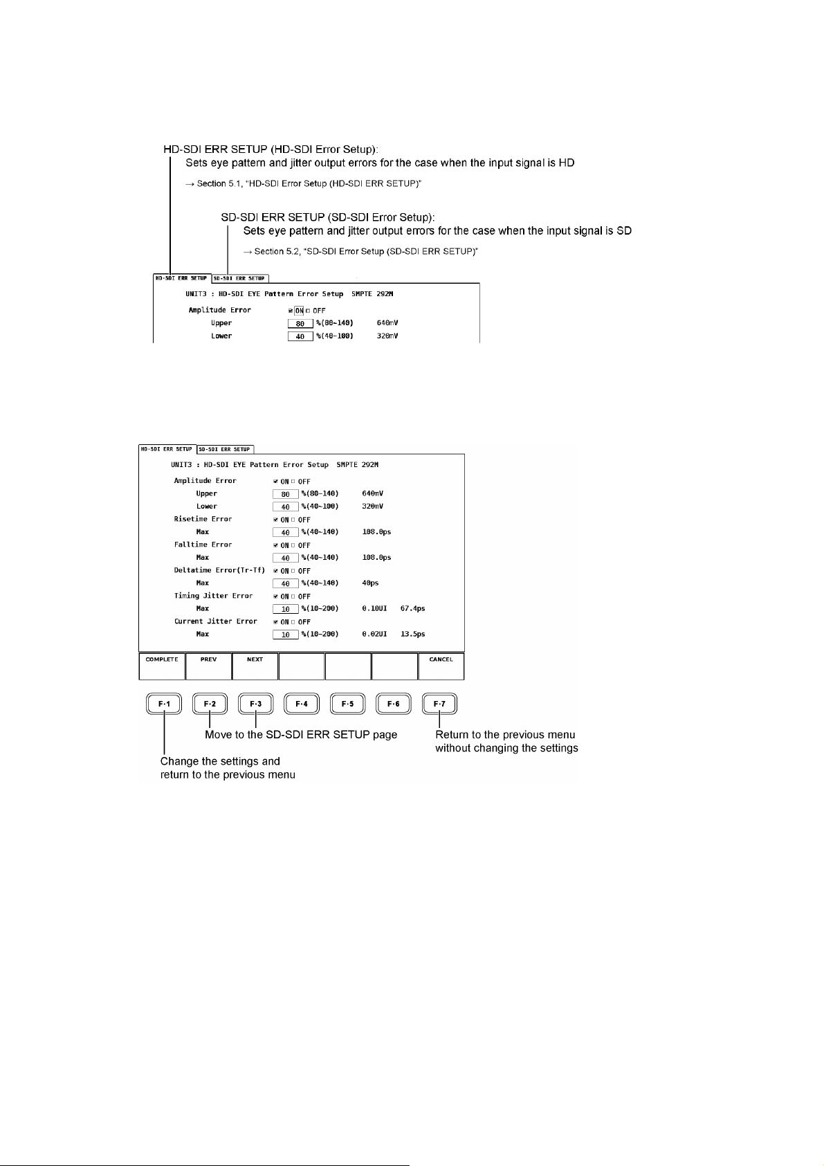
5.1 HD-SDI Error Setup (HD-SDI ERR SETUP)
The HD-SDI ERR SETUP page is used to specify settings related to the error detection of the
eye pattern waveform and jitter waveform for the HD input signal.
12
Page 16

5. CONFIGURING ERROR DETECTION
• Setting the Items
Use the function dial (F•D) at the front panel and place checks in the relevant setup items.
Checking the Setup Items
1. Turn the function dial (F•D) to move the cursor.
2. Press the function dial (F•D) at the relevant item.
A red check appears in the box of the selected item, and the check placed on the
previously selected item clears.
Entering Values
1. Turn the function dial (F•D) to move the cursor.
2. Press the function dial (F•D).
On the LV 5800 and LV 7800, the text box turns yellow-green.
On the LV 7380, the cursor turns yellow.
3. Turn the function dial (F•D) to select the desired value.
4. Press the function dial (F•D).
The specified value appears in the input box.
Applying the Settings
1. Press F・1 COMPLETE.
The settings are applied. After the settings are applied, the previous menu is displayed.
The settings are applied only if you carry out this step.
If you do not want to apply the settings, press F•7 CANCEL. The settings are not applied,
and the previous menu is displayed.
Applying the Setup Items at Once
You can also apply the settings all at once after specifying the settings for both tabs. To do so,
after specifying the settings for the current tab, press F•3 NEXT or F•2 PREV to move
between tabs and continue specifying the settings for the next tab, and then press F•1
COMPLETE when you have finished.
* Press F•7 CANCEL to not apply any of the specified settings.
13
Page 17

5. CONFIGURING ERROR DETECTION
• Description of Setup Items
• Amplitude Error
Controls the error detection related to the amplitude of the eye pattern waveform.
ON: Enables error detection
OFF: Disables error detection (initial setting)
If you specify ON, you can set the upper and lower limits.
The lower limit must be less than or equal to the upper limit.
Upper: Sets the upper limit (selectable range: 80 to 140 % (640 to 1120 mV))
Lower: Sets the lower limit (selectable range: 40 to 100 % (320 to 800 mV))
• Risetime Error
Controls the error detection related to the rise time of the eye pattern waveform.
ON: Enables error detection
OFF: Disables error detection (initial setting)
If you specify ON, you can set the upper limit.
Max: Sets the upper limit (selectable range: 40 to 140 % (108.0 to 378.0 ps))
• Falltime Error
Controls the error detection related to the fall time of the eye pattern waveform.
ON: Enables error detection
OFF: Disables error detection (initial setting)
If you specify ON, you can set the upper limit.
Max: Sets the upper limit (selectable range: 40 to 140 % (108.0 to 378.0 ps))
• Deltatime Error
Controls the error detection related to the difference between the rise time and the fall time
of the eye pattern waveform. When the measured values exceed the specified value, Tr
and Tf are both displayed in red.
ON: Enables error detection
OFF: Disables error detection (initial setting)
If you specify ON, you can set the upper limit.
Max: Sets the upper limit (selectable range: 40 to 140 % (40 to 140 ps))
• Timing Jitter Error
Controls the error detection related to the timing jitter of the eye pattern waveform and
jitter waveform.
ON: Enables error detection
OFF: Disables error detection (initial setting)
If you specify ON, you can set the upper limit.
Max: Sets the upper limit (selectable range: 10 to 200 % (0.10 to 2.00 UI, 67.4 to
1348.0 ps))
14
Page 18

5. CONFIGURING ERROR DETECTION
• Current Jitter Error
Controls the error detection related to the current jitter of the eye pattern waveform and
jitter waveform.
ON: Enables error detection
OFF: Disables error detection (initial setting)
If you specify ON, you can set the upper limit.
Max: Sets the upper limit (selectable range: 10 to 200 % (0.02 to 0.40 UI, 13.5 to
270.0 ps))
• HD-SDI ERR SETUP Configuration Example
To satisfy the SMPTE 292M measurement standards, set HD-SDI ERR SETUP as follows.
Item Setting Corresponding value
Upper 110 % 880 mVAmplitude Error
Lower 90 % 720 mV
Rise Time Error Max 100 % 270 ps
Fall Time Error Max 100 % 270 ps
Delta Time Error (Tr-Tf) Max 100 % 100 ps
Timing Jitter Error Max 100 % 1.0 UI
Current Jitter Error * Max 100 % 0.2 UI
* SMPTE 292M requires that the alignment jitter be measured. Set the LV 58SER02 filter to
ALIGNMENT or 100 kHz, and then use the measured current jitter value to search for errors.
(The current jitter is the jitter value for the currently selected filter.)
15
Page 19

5. CONFIGURING ERROR DETECTION
5.2 SD-SDI Error Setup (SD-SDI ERR SETUP)
The SD-SDI ERR SETUP page is used to specify settings related to the error detection of the
eye pattern waveform and jitter waveform for the SD input signal.
• Setting the Items
[See also]Setting each item → Section 5.1, “HD-SDI Error Setup (HD-SDI ERR SETUP)
• Description of Setup Items
• Amplitude Error
Controls the error detection related to the amplitude of the eye pattern waveform.
ON: Enables error detection
OFF: Disables error detection (initial setting)
If you specify ON, you can set the upper and lower limits.
The lower limit must be less than or equal to the upper limit.
Upper: Sets the upper limit (selectable range: 80 to 140 % (640 to 1120 mV))
Lower: Sets the lower limit (selectable range: 40 to 100 % (320 to 800 mV))
• Risetime Error
Controls the error detection related to the rise time of the eye pattern waveform.
ON: Enables error detection
OFF: Disables error detection (initial setting)
If you specify ON, you can set the upper limit.
Max: Sets the upper limit (selectable range: 40 to 140 % (0.60 to 2.10 ns))
• Falltime Error
Controls the error detection related to the fall time of the eye pattern waveform.
ON: Enables error detection
OFF: Disables error detection (initial setting)
16
Page 20

5. CONFIGURING ERROR DETECTION
If you specify ON, you can set the upper limit.
Max: Sets the upper limit (selectable range: 40 to 140 % (0.60 to 2.10 ns))
• Deltatime Error
Controls the error detection related to the difference between the rise time and the fall time
of the eye pattern waveform. When the measured values exceed the specified value, Tr
and Tf are displayed in red.
ON: Enables error detection
OFF: Disables error detection (initial setting)
If you specify ON, you can set the upper limit.
Max: Sets the upper limit (selectable range: 40 to 140 % (0.20 to 0.70 ns))
• Timing Jitter Error
Controls the error detection related to the timing jitter of the eye pattern waveform and
jitter waveform.
ON: Enables error detection
OFF: Disables error detection (initial setting)
If you specify ON, you can set the upper limit.
Max: Sets the upper limit (selectable range: 10 to 200 % (0.02 to 0.40 UI, 0.07 to
1.48 ns))
• Current Jitter Error
Controls the error detection related to the current jitter of the eye pattern waveform and
jitter waveform.
ON: Enables error detection
OFF: Disables error detection (initial setting)
If you specify ON, you can set the upper limit.
Max: Sets the upper limit (selectable range: 10 to 200 % (0.02 to 0.40 UI, 0.07 to
1.48 ns))
• SD-SDI ERR SETUP Configuration Example
To satisfy the SMPTE 259M measurement standards, set SD-SDI ERR SETUP as follows.
Item Setting Corresponding value
Upper 110 % 880 mVAmplitude Error
Lower 90 % 720 mV
Rise Time Error Max 100 % 1.5 ns
Fall Time Error Max 100 % 1.5 ns
Delta Time Error (Tr-Tf) Max 100 % 0.5 ns
Timing Jitter Error Max 100 % 0.2 UI
Current Jitter Error * Max 100 % 0.2 UI
* SMPTE 259M requires that the alignment jitter be measured. Set the LV 58SER02 filter to
ALIGNMENT or 1kHz, and then use the measured current jitter value to search for errors.
(The current jitter is the jitter value for the currently selected filter.)
17
Page 21
6. EYE PATTERN WAVEFORM AND JITTER WAVEFORM DISPLAY
6. EYE PATTERN WAVEFORM AND JITTER WAVEFORM DISPLAY
The LV 58SER02 displays the eye pattern waveform and jitter waveform of the signal applied to
the LV 58SER01A (SDI INPUT) or LV 58SER04 (MPEG DECODER) or LV 7380(MULTI SDI
RASTERIZER) input. *1
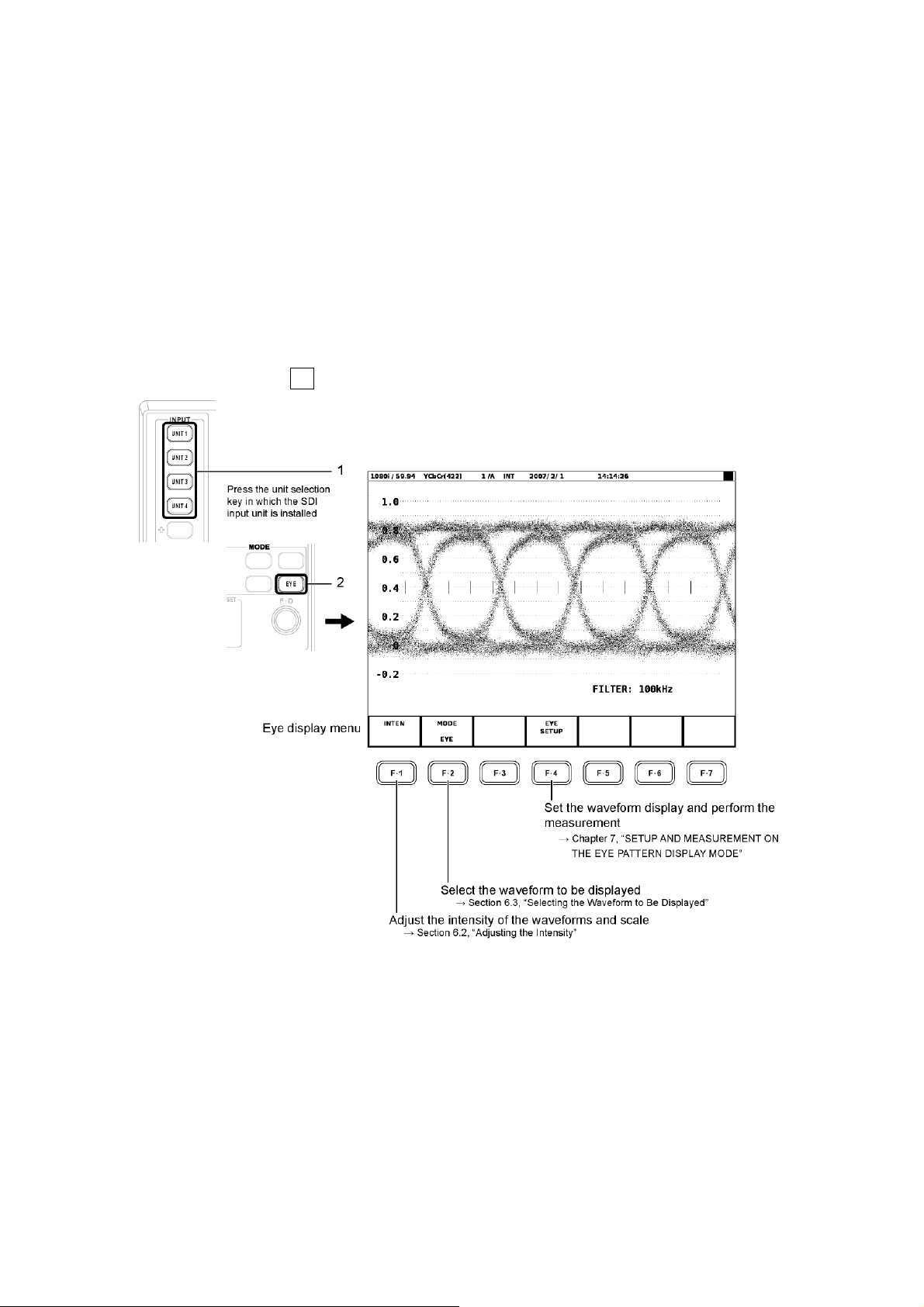
On the LV 5800 or LV 7800, to display the eye pattern, press the unit selection key (UNIT1 to
UNIT4) of the slot in which the LV 58SER01A (SDI INPUT) or LV 58SER04 (MPEG DECODER)
is installed, and then press the EYE key. *2
On the LV 7380, all you have to do is press the EYE key to display the eye pattern.
Press the EYE key to display the eye pattern or jitter waveform and a menu. The eye pattern
waveform display shows the eye display menu; the jitter waveform display shows the jitter
display menu. Press F•2 MODE to switch between the displayed waveforms.
*1 Jitter waveform display is not available for DVB-ASI signal input.
*2 If you press the unit selection key in which this unit is installed, and error message will be displayed.
• Simultaneous Display in the Multi Screen Display
The maximum simultaneous displays are two displays consisting of the eye pattern display and
jitter display.
If the selected area is set to eye pattern display in advance, the area selected later is set to the
jitter display, and vice versa.
To perform simultaneous display, the input signal must be the same. Select the same unit
number and same channel (A or B) for the two screens to be displayed simultaneously.
18
Page 22

6. EYE PATTERN WAVEFORM AND JITTER WAVEFORM DISPLAY
6.1 Setting the Waveform Display Position
On the LV 5800 and LV 7800, you can adjust the positions of eye-pattern and jitter waveforms
using the V POS (vertical position) and H POS (horizontal position) knobs on the front panel.
On the LV 7380, you can adjust the position by using F・D 1 H POS and F・D 2 V POS in the
eye display menu.
• V POS Control
Adjusts the vertical display position of the eye pattern or jitter waveform.
Press the control to reset the vertical display position of the waveform to the reference
position.
• H POS Control
Adjusts the horizontal display position of the eye pattern or jitter waveform.
Press the control to reset the horizontal display position of the waveform to the reference
position.
19
Page 23

6. EYE PATTERN WAVEFORM AND JITTER WAVEFORM DISPLAY
6.2 Adjusting the Intensity
Carry out the procedure below to display the intensity adjustment menu for the eye pattern
waveform and scale.
6.2.1 Adjusting the Intensity of the Waveform
Carry out the procedure below to adjust the intensity of the waveform.
Adjustment range: -128 to 127 .....................(LV 5800, LV 7800)
-8 to 7 .............................(LV 7380)
• Procedure
・ For the LV 5800 and LV 7800
EYE → F•1 INTEN → F•1 EYE INTEN : -128 to 32 to 127
・ For the LV 7380
EYE → F・1 INTEN → F・D 1 EYE INTEN:-8 to 2 to 7
After carrying out the procedure above, turn the function dial (F・D). Press the function dial
(F・D) to return to the default value (32 or 2).
20
Page 24

6. EYE PATTERN WAVEFORM AND JITTER WAVEFORM DISPLAY
6.2.2 Adjusting the Scale Intensity
Carry out the procedure below to adjust the intensity of the scale.
Adjustment range: -8 to 7
• Procedure
・ For the LV 5800 and LV 7800
EYE → F•1 INTEN → F•2 SCALE INTEN : -8 to 4 to 7
・ For the LV 7380
EYE → F・1 INTEN → F・D 2 SCALE INTEN:-8 to 4 to 7
After carrying out the procedure above, turn the function dial (F•D). Press the function dial
(F•D) to return to the default value (4).
6.3 Selecting the Waveform to Be Displayed
Carry out the procedure below to select the waveform to be displayed. The F・4 key menu
varies depending on this selection.
This menu will not appear when the slot that contains the LV 58SER04 is selected.
• Procedure
EYE → F•2 MODE : EYE / JITTER
If you set F•2 MODE to EYE, F•4 EYE SETUP appears. You can carry out various settings and
measurement on the eye pattern waveform.
[See also] Setup and measurement on the eye pattern waveform display → Chapter 7, “SETUP AND
MEASUREMENT ON THE EYE PATTERN DISPLAY MODE.”
If you set F・2 MODE to JITTER, F・4 JITTER SETUP appears. You can carry out various
settings and measurement on the jitter waveform.
[See also] Setup and measurement on the jitter waveform display → Chapter 8, “SETUP AND
MEASUREMENT ON THE JITTER DISPLAY MODE.”
6.4 Selecting Which Link to Display
When the link format is set to dual, carry out the procedure below to select whether to display
the waveform of link A or link B.
• Procedure
EYE → F・6 LINK SELECT:LINK A / LINK B
21
Page 25

6. EYE PATTERN WAVEFORM AND JITTER WAVEFORM DISPLAY
6.5 Configuring Thumbnails (Only on the LV 7380)
In the LV 7380 eye pattern display, you can display thumbnails of the audio-meter and picture
displays. You can set which thumbnails are displayed using the thumbnail configuration menu.
EYE → F・7 THUMBNAIL →
6.5.1 Displaying the Audio Meter
To select whether to display the audio meter, carry out the procedure below.
• Procedure
EYE → F・7 THUMBNAIL → F・1 AUDIO METER:ON / OFF
6.5.2 Selecting the Audio Meter Display Format
To select the audio meter display format, follow the procedure below.
HORIZ1: 1st GROUP is displayed on the left side, and 2nd GROUP is displayed on
the right side.
HORIZ2: 1st GROUP is displayed on the top two levels and 2nd GROUP is displayed
on the bottom two levels.
• Procedure
EYE → F・7 THUMBNAIL → F・2 LAYOUT:HORIZ1 / HORIZ2
6.5.3 Picture Display
To select whether to display the picture, carry out the procedure below.
• Procedure
EYE → F・7 THUMBNAIL → F・3 PICTURE:ON / OFF
22
Page 26

6.6 Event Log
The event names that appear in the event logs of the LV 58SER01A(SDI INPUT), LV
58SER04(MPEG DECODER), and LV 7380(MULTI SDI RASTERIZER) are described below.
Of the events listed below, only the items whose error detection you enabled in chapter 5,
"Configuring Error Detection," are displayed.
For explanations of the event log, see the instruction manual for the device you are using.
Event Name Description
EYE_HD_AMP HD-SDI Amplitude Error
EYE_HD_TR HD-SDI Risetime Error
EYE_HD_TF HD-SDI Falltime Error
EYE_HD_TR_TF HD-SDI Deltatime Error
EYE_HD_T_JIT HD-SDI Timing Jitter Error
EYE_HD_A_JIT HD-SDI Current Jitter Error
EYE_SD_AMP SD-SDI Amplitude Error
EYE_SD_TR SD-SDI Risetime Error
EYE_SD_TF SD-SDI Falltime Error
EYE_SD_TR_TF SD-SDI Deltatime Error
EYE_SD_T_JIT SD-SDI Timing Jitter Error
EYE_SD_A_JIT SD-SDI Current Jitter Error
6. EYE PATTERN WAVEFORM AND JITTER WAVEFORM DISPLAY
23
Page 27
7. SETUP AND MEASUREMENT ON THE EYE PATTERN DISPLAY MODE
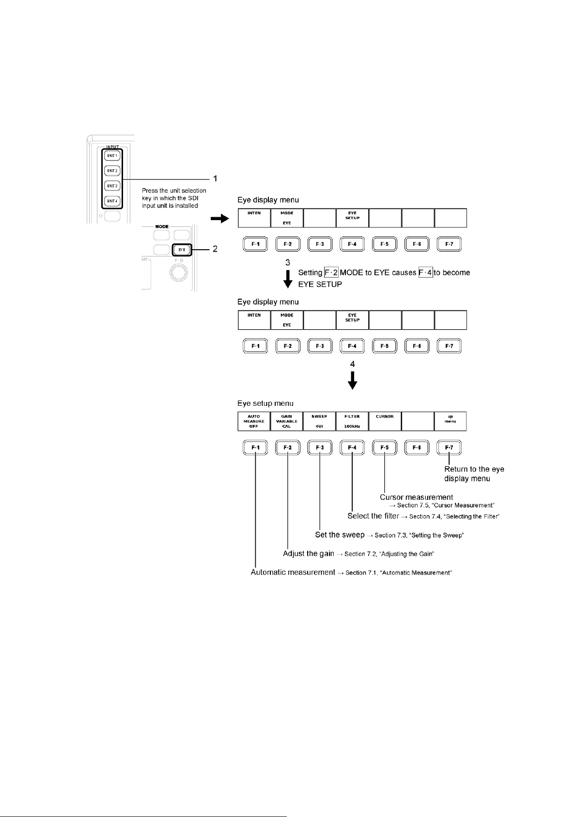
7. SETUP AND MEASUREMENT ON THE EYE PATTERN DISPLAY
MODE
Carry out the procedure below to display the eye setup menu used to set and measure the eye
pattern waveform.
24
Page 28

7. SETUP AND MEASUREMENT ON THE EYE PATTERN DISPLAY MODE
7.1 Automatic Measurement
Automatically measures the amplitude, the rise time, the fall time, and the amount of jitter of
the eye pattern.
• Procedure
EYE → set F•2 MODE to EYE → F•4 EYE SETUP→ F•1 AUTO MEASURE : ON / OFF
If automatic measurement is turned ON, the amplitude, the rise time (Tr), the fall time (Tf), and
the amount of jitter are displayed numerically for the current eye pattern on the screen.
The automatic measurement values of the eye pattern (Amp, Tr, and Tf) are determined
through image processing from the waveform data on the screen. This achieves correlation
with the values obtained by measuring the eye pattern using a cursor.
In addition, the automatic measurement values of the jitter (T.J and C.J) display the values that
are measured in the jitter display mode. The measurement method is phase modulator.
The timing jitter and current jitter values will not appear when the slot that contains the LV
58SER04 (MPEG DECODER) is selected.
7.2 Adjusting the Gain
Carry out the procedure below to adjust the gain of the waveform display.
Adjustment range: ×0.50 to ×2.00
• Procedure
EYE → set F•2 MODE to EYE → F•4 EYE SETUP→ F•2 GAIN VARIABLE : CAL /
VARIABLE
25
Page 29

7. SETUP AND MEASUREMENT ON THE EYE PATTERN DISPLAY MODE
Turn the function dial (F・D) with F・2 GAIN VARIABLE set to VARIABLE to change the
waveform display magnification in the range of ×0.50 to ×2.00. Press the function dial (F・D) to
return to the default value (×1.00). The magnification is displayed at the screen.
×0.50 ×2.00
7.3 Setting the Sweep
Carry out the procedure below to set the display periods of the eye pattern.
2UI: Displays 2 eye pattern waveforms
4UI: Displays 4 eye pattern waveforms
16UI: Displays 16 eye pattern waveforms
• Procedure
EYE → set F•2 MODE to EYE → F•4 EYE SETUP→ F•3 SWEEP : 2UI / 4UI / 16UI
2UI ×4UI 16UI
7.4 Selecting the Filter
Select the bandwidth for the jitter measurement of the SDI signal. This setting is linked to the
filter setting in the jitter display mode.
[See also]Selecting the filter of the jitter display mode → Section 8.4, “Selecting the Filter”
100 kHz: Displays the jitter components for frequencies greater than or equal to 100
kHz
1 kHz: Displays the jitter components for frequencies greater than or equal to 1 kHz
100 Hz: Displays the jitter components for frequencies greater than or equal to 100
Hz
10 Hz: Displays the jitter components for frequencies greater than or equal to 10 Hz
TIMING*: Displays the timing jitter (10 Hz or greater)
ALIGNMENT*: Displays the alignment jitter (100 kHz or greater for HD, 1 kHz or greater for
SD).
* Will not appear when a slot that contains the LV 58SER04 (MPEG DECODER) is selected.
26
Page 30
7. SETUP AND MEASUREMENT ON THE EYE PATTERN DISPLAY MODE
• Procedure
• When a slot that contains the LV 58SER01A (SDI INPUT) is selected:
EYE → set F•2 MODE to EYE → F•4 EYE SETUP→ F•4 FILTER : 100 kHz / 1 kHz / 100 Hz /
10 Hz / TIMING / ALIGNMENT
• When a slot that contains the LV 58SER04 (MPEG DECODER) is selected:
EYE → set F•2 MODE to EYE → F•4 EYE SETUP→ F•4 FILTER : 100kHz / 1kHz / 100Hz /
10Hz
If you select 10 Hz, the eye pattern jitter over the entire bandwidth greater than or equal to 10
Hz is displayed. Likewise, if you select 100 kHz, only the jitter over the bandwidth greater than
or equal to 100 kHz is displayed. The selected filter is displayed at the screen.
This setting enables you to determine the frequency components of the jitter of the SDI input
signal.
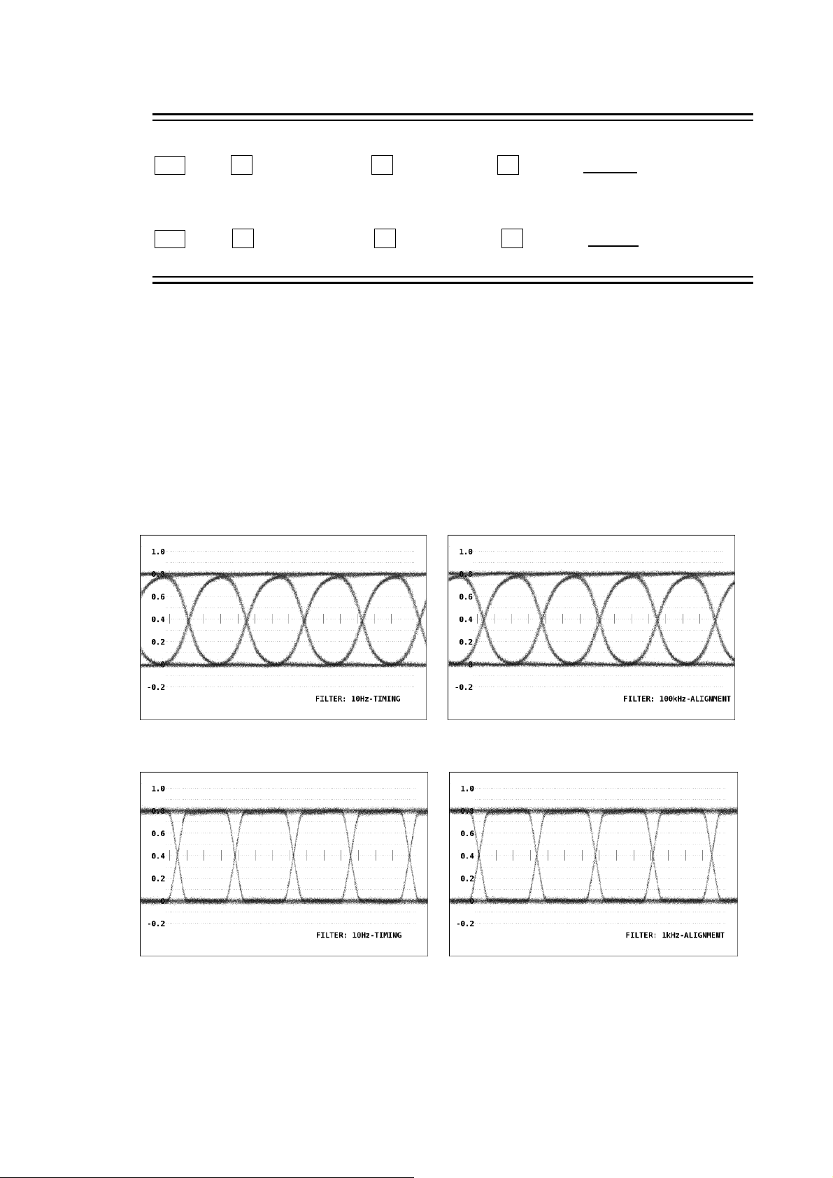
In addition, SMPTE stipulates that the timing jitter and alignment jitter be measured.
The filter setting for this case is 10 Hz if you select TIMING. If you select ALIGNMENT, the filter
setting changes automatically according to the input signal. It is 100 kHz for HD-SDI and 1 kHz
for SD-SDI.
If the input signal is HD
TIMING ALIGNMENT
If the input signal is SD
TIMING ALIGNMENT
27
Page 31

7. SETUP AND MEASUREMENT ON THE EYE PATTERN DISPLAY MODE
7.5 Cursor Measurement
Cursor measurement is used to measure voltage, time, and other parameters. The REF and
DELTA cursors are used to measure the voltage and time between two points on a waveform.
Carry out the procedure below to display the cursor measurement menu used to perform
cursor measurements.
28
Page 32

7. SETUP AND MEASUREMENT ON THE EYE PATTERN DISPLAY MODE
7.5.1 Displaying the Cursors
Carry out the procedure below to show or hide the cursors.
ON: Shows the cursors
OFF: Hides the cursors
• Procedure
EYE → set F•2 MODE to EYE → F•4 EYE SETUP→ F•5 CURSOR → F•1 CURSOR : ON
/ OFF
Turn the function dial (F•D) to move the cursor to the measurement point on the waveform.
The measured value between the cursors is displayed at the lower right of the screen.
OK
7.5.2 Selecting X-Axis or Y-Axis Cursor
Carry out the procedure below to select the axis to perform the cursor measurement from
X-axis (time) and Y-axis (amplitude).
Y: Y (amplitude) axis
X: X (time) axis
Tr,Tf: Rise or fall time
• Procedure
EYE → set F•2 MODE to EYE → F•4 EYE SETUP→ F•5 CURSOR → F•2 XY SEL : X / Y /
Tr,Tf
29
Page 33

7. SETUP AND MEASUREMENT ON THE EYE PATTERN DISPLAY MODE
7.5.3 Selecting the Cursor Measurement Unit
Carry out the procedure below to select the unit for the cursor axis selected in “Selecting
X-Axis or Y-Axis Cursor.”
X-Axis Cursor Unit
sec: Displays seconds.
Hz: Displays the frequency taking the interval between the cursors to be 1
period.
UIp-p: Displays using a unit where one eye pattern waveform is taken to be 1
UIp-p.
Y-Axis Cursor Unit
V: Displays volts.
%: Displays the ratio where the difference between two arbitrary points set by
REF SET is taken to be 100 %.
• Procedure
• If X is selected in “Selecting X-Axis or Y-Axis Cursor”
EYE → set F•2 MODE to EYE → F•4 EYE SETUP→ F•5 CURSOR → F•2 XY SEL to
select X → F•3 X UNIT : sec / Hz / UIp-p
• If Y is selected in “Selecting X-Axis or Y-Axis Cursor”
EYE → set F•2 MODE to EYE → F•4 EYE SETUP→ F•5 CURSOR → F•2 XY SEL to
select Y → F•3 Y UNIT : V / %
X UNIT: sec / Y UNIT: V X UNIT: Hz / Y UNIT: V X UNIT: UIp-p / Y UNIT: V
If you set F•3 Y UNIT to %, F•5 REF SET is displayed. Align the cursors with the waveform
and press F•5 REF SET to set that cursor range to 100 %.
Y UNIT: Before pressing % > REF SET Y UNIT: After pressing % > REF SET
30
Page 34

7. SETUP AND MEASUREMENT ON THE EYE PATTERN DISPLAY MODE
Unit interval (UI) refers to the width of 1 clock cycle. The value is displayed where 1 clock
cycle is taken to be 100%. The unit is UIp-p.
If the bit rate of the HD-SDI signal is 1.485/1.001 Gbps, 1 UI is as follows:
1 UI = 1/1.4835 GHz = 674.1 ps
And, the measured jitter value (UIp-p) is as follows:
Jitter value (UIp-p) = measured value (ps)/width of 1 clock cycle (ps)
= measured value (ps)/674.1 (ps)
If the bit rate of the HD-SDI signal is 1.485 Gbps, 1 UI is as follows:
1 UI = 1/1.485 GHz = 673.4 ps
And, the measured jitter value (UIp-p) is as follows:
Jitter value (UIp-p) = measured value (ps)/width of 1 clock cycle (ps)
= measured value (ps)/673.4 (ps)
The SD-SDI and DVB-ASI signal bit rates are 270 Mbps. Therefore, 1 UI is as follows:
1 UI = 1/270 MHz = 3.7 ns
And, the measured jitter value (UIp-p) is as follows:
Jitter value (UIp-p) = measured value (ns)/width of 1 clock cycle (ns)
7.5.4 Moving the Cursors
On the LV 5800 and LV 7800, to select the type of cursor to move, carry out the procedure
below.
REF: REF cursor (Cyan)
DELTA: DELTA cursor (Green)
TRACK: REF and DELTA cursors
• Procedure
EYE → set F•2 MODE to EYE → F•4 EYE SETUP→ F•5 CURSOR → F•4 FD VAR : REF /
DELTA / TRACK
After carrying out the procedure above, turn the function dial (F•D) to move the selected
cursor.
You can also press the function dial instead of pressing F•4 FD VAR to select the cursor type.
Each time you press the function dial, the cursor is selected in the following order: REF,
DELTA, and TRACK.
= measured value (ns)/3.7 (ns)
On the LV 7380, carry out the procedure below to move the cursors.
REF cursor (Cyan): Set F・4 FD VAR TRACK to OFF, and use F・D 1 REF to
move the cursor.
DELTA cursor (Green): Use F・D 2 DELTA.
REF and DELTA cursors: Set F・4 FD VAR TRACK to ON, and use F・D 1 TRACK to
move the cursor.
You can also change the setting of F・4 FD VAR TRACK by pressing F・D 1. You can switch
the positions of the REF and DELTA cursors by pressing F・D 2.
31
Page 35

7. SETUP AND MEASUREMENT ON THE EYE PATTERN DISPLAY MODE
7.5.5 Measuring Using Cursors Sample
Measuring Amplitude (Amp) (On the LV 5800)
Perform the procedure below to measure the eye pattern amplitude (Amp) in volts.
1. Set F•2 XY SEL to Y.
2. Set F•3 Y UNIT to V.
3. Set F•4 FD VAR to REF, and align the blue cursor with one of the peaks of the eye
pattern.
4. Set F•4 FD VAR to DELTA, and align the green cursor with the other peak of the eye
pattern.
The eye pattern amplitude appears next to the Y at the bottom right of the screen (800.0
mV in the example below).
• To Measure the Amplitude as a Percentage
Press F•3 Y UNIT, and select %. The amplitude will be measured as a percentage of the
amplitude at the time when you pressed F•5 REF SET.
• To Switch between REF and DELTA Using the Function Dial (F•D)
Each time you press the function dial (F•D), the movable cursor switches from
REF (the blue cursor) to DELTA (the green cursor) to TRACK (both cursors)
in that order. An upside down triangle appears next to the cursors that you can move.
• To Measure along the Time Axis (X-Axis)
Press F•2 XY SEL, and select X. The measured value between the cursors appears
next to the X at the bottom right of the screen.
32
Page 36

7. SETUP AND MEASUREMENT ON THE EYE PATTERN DISPLAY MODE
Measuring Rise Time (Tr) and Fall Time (Tf) (On the LV 5800)
Perform the procedure below to measure the rise time (Tr) and fall time (Tf) of an eye
pattern.
1. Set F•2 XY SEL to Tr,Tf.
2. Using the Y cursors, align the REF and DELTA cursors to the eye pattern amplitude.
3. Press the F•5 REF SET key.
The Y cursors move to the 20 % and 80 % positions of the amplitude, and then F•2 XY
SEL is automatically set to X.
4. Align the X cursors to the cross points between 20 % and 80 % cursors and the
waveform.
The Tr and Tf are measured.
The measured value between the cursors appears next to X at the bottom right of the
screen.
33
Page 37

8. SETUP AND MEASUREMENT ON THE JITTER DISPLAY MODE
8. SETUP AND MEASUREMENT ON THE JITTER DISPLAY MODE
The jitter display mode is used to extract only the jitter components from the SDI signal using
phase modulation and display the result on the time axis. In this mode, jitters can be accurately
measured even if the eye pattern is not open after the signal is transmitted over a long cable or if
a jitter of more than 1 UIp-p is present.
Also, because the length of the horizontal axis is equal to one line or field of the video signal, you
can observe jitter that is synchronized with lines and fields.
Carry out the procedure below to display jitter setup menu for the jitter waveform.
* Jitter waveform display is not available for DVB-ASI signal input.
34
Page 38

8.1 Peak Hold
You can use the peak hold function of the jitter waveform to hold the maximum value (time) of
the jitter. Carry out the procedure below to display the peak hold menu and specify the
settings.
8. SETUP AND MEASUREMENT ON THE JITTER DISPLAY MODE
35
Page 39

8. SETUP AND MEASUREMENT ON THE JITTER DISPLAY MODE
8.1.1 Setting the Peak Hold
Carry out the procedure below to set whether to measure the peak value of the jitter.
ON: Enables the measurement of the jitter peak value.
OFF: Disables the measurement of the jitter peak value.
• Procedure
EYE → set F•2 MODE to JITTER → F•4 JITTER SETUP→ F•1 PEAK HOLD → F•1 PEAK
HOLD : ON / OFF
If you set F•1 PEAK HOLD to ON, the peak value measurement will start. If the measured
jitter value exceeds the measurable range, OVER will appear as the peak value. For
information about the measurable range for jitter, see section 8.2, “Selecting the Gain.”
Press F•2 CLEAR to clear the current peak value and restart the measurement.
36
Page 40

8. SETUP AND MEASUREMENT ON THE JITTER DISPLAY MODE
8.2 Selecting the Gain
Carry out the procedure below to select the gain of the jitter waveform.
×1: x1 gain
×2: x2 gain
×8: x8 gain
• Procedure
EYE → set F•2 MODE to JITTER → F•4 JITTER SETUP→ F•2 GAIN MAG : ×1 / ×2 / ×8
• About the *UNDER RANGE* Message
When F•2 GAIN MAG is set to ×1 or ×2 and the measured jitter value is below 0.60 UI, the
measured value becomes yellow and “*UNDER RANGE*” appears at the screen. If this
happens, set F•2 GAIN MAG to ×8.
• About the OVER Message
If the measured jitter value exceeds the measurable range, OVER will appear in red as the
measured value at the screen. If this happens, set F•2 GAIN MAG to ×8 → ×2 → ×1, in that
order.
The table below shows the measurable ranges for each gain setting.
F•2 GAIN MAG *UNDER RANGE* Appears Measurable Range OVER Appears
×1 0.00 to 0.60 UI 0.61 to 10.00 UI 10.01 UI or greater
×2 0.00 to 0.60 UI 0.61 to 5.20 UI 5.21 UI or greater
×8 Does not appear 0.00 to 1.30 UI 1.31 UI or greater
37
Page 41

8. SETUP AND MEASUREMENT ON THE JITTER DISPLAY MODE
8.3 Setting the Sweep
Carry out the procedure below to set the sweep time of the jitter waveform.
1H: Displays the jitter waveform for 1 line
2H: Displays the jitter waveform for 2 lines
1V: Displays the jitter waveform for 1 field
2V: Displays the jitter waveform for 2 fields
• Procedure
EYE → set F•2 MODE to JITTER → F•4 JITTER SETUP→ F•3 SWEEP : 1H / 2H / 1V / 2V
8.4 Selecting the Filter
Carry out the procedure below to select the frequency bandwidth of the jitter to be displayed.
This setting is linked to the filter setting in the eye pattern display mode.
[See also]Selecting the filter of the eye pattern display mode → Section 7.4, “Selecting the Filter”
100kHz: Displays the jitter components for frequencies greater than or equal to 100
kHz
1kHz: Displays the jitter components for frequencies greater than or equal to 1 kHz
100Hz: Displays the jitter components for frequencies greater than or equal to 100 Hz
10Hz: Displays the jitter components for frequencies greater than or equal to 10 Hz
TIMING: Displays the timing jitter (10 Hz or greater)
ALIGNMENT: Displays the alignment jitter (100 kHz or greater for HD, 1
kHz or greater for SD).
• Procedure
EYE → set F•2 MODE to JITTER → F•4 JITTER SETUP→ F•4 FILTER : 100 kHz / 1 kHz / 100
Hz / 10 Hz / TIMING / ALIGNMENT
38
Page 42

8. SETUP AND MEASUREMENT ON THE JITTER DISPLAY MODE
8.5 Cursor Measurement
Cursor measurement is used to measure the jitter time. Cursors are used to measure the time
between two points on the waveform.
Carry out the procedure below to display the cursor measurement menu used to perform
cursor measurements.
39
Page 43

8. SETUP AND MEASUREMENT ON THE JITTER DISPLAY MODE
8.5.1 Displaying the Cursors
Carry out the procedure below to show or hide the cursors.
ON: Shows the cursors
OFF: Hides the cursors
• Procedure
EYE → set F•2 MODE to JITTER → F•4 JITTER SETUP→ F•5 CURSOR → F•1 CURSOR :
ON / OFF
Turn the function dial (F•D) to move the cursor to the measurement point on the waveform.
The measured value between the cursors is displayed at the lower right of the screen.
OK
8.5.2 Selecting X-Axis or Y-Axis Cursor
Carry out the procedure below to select the axis to perform the cursor measurement from
X-axis (time) and Y-axis (amplitude).
X : X (time) axis
Y: Y (amplitude) axis
• Procedure
EYE → set F•2 MODE to JITTER → F•4 JITTER SETUP→ F•5 CURSOR → F•2 XY SEL :
X / Y
40
Page 44

8. SETUP AND MEASUREMENT ON THE JITTER DISPLAY MODE
8.5.3 Selecting the Cursor Measurement Unit
Carry out the procedure below to select the unit for the cursor axis selected in “Selecting
X-Axis or Y-Axis Cursor.”
X-Axis Cursor Unit
sec: Displays the time in seconds
Hz: Displays the frequency taking the interval between the cursors to be 1 period
Y-Axis Cursor Unit
sec: Displays the time in seconds
UIp-p: Displays using a unit where one jitter waveform is taken to be 1 UIp-p.
• Procedure
• If X is selected in “Selecting X-Axis or Y-Axis Cursor”
EYE → set F•2 MODE to JITTER → F•4 JITTER SETUP→ F•5 CURSOR → F•2 XY
SEL to select X → F•3 X UNIT : sec / Hz
• If Y is selected in “Selecting X-Axis or Y-Axis Cursor”
EYE → set F•2 MODE to JITTER → F•4 JITTER SETUP→ F•5 CURSOR → F•2 XY
SEL to select Y → F•3 Y UNIT : sec / UIp-p
X UNIT: sec / Y UNIT: sec X UNIT: Hz / Y UNIT: UI
41
Page 45

8. SETUP AND MEASUREMENT ON THE JITTER DISPLAY MODE
8.5.4 Moving the Cursors
On the LV 5800 and LV 7800, to select the type of cursor to move, carry out the procedure
below.
REF: REF cursor (Cyan)
DELTA: DELTA cursor (Green)
TRACK: REF and DELTA cursors
• Procedure
EYE → set F•2 MODE to JITTER → F•4 JITTER SETUP→ F•5 CURSOR → F•4 FD VAR :
REF / DELTA / TRACK
After carrying out the procedure above, turn the function dial (F•D) to move the selected
cursor.
You can also press the function dial instead of pressing F•4 FD VAR to select the cursor type.
Each time you press the function dial, the cursor is selected in the following order: REF,
DELTA, and TRACK.
On the LV 7380, carry out the procedure below to move the cursors.
REF cursor (Cyan): Set F・4 FD VAR TRACK to OFF, and use F・D 1 REF to
DELTA cursor (Green): Use F・D 2 DELTA.
REF and DELTA cursors: Set F・4 FD VAR TRACK to ON, and use F・D 1 TRACK to
You can also change the setting of F・4 FD VAR TRACK by pressing F・D 1. You can switch
the positions of the REF and DELTA cursors by pressing F・D 2.
8.6 Jitter Output
In jitter display mode, the jitter component of the input signal is output from the JITTER OUT
connector on the back of the LV 58SER02. Only the timing jitter is output (10 Hz or greater),
regardless of the filter setting.
The output can also be connected to a spectrum analyzer to perform simplified frequency
analysis of the jitter signal. The output can also be connected to an FFT analyzer to perform
simplified frequency analysis of the jitter signal.
The output level is 250 mV ± 20 % (with a 75 Ω terminator, an input jitter amplitude of 1 UI, and
an input jitter frequency of 10 kHz).
* The LV 7380 (MULTI SDI RASTERIZER) cannot produce jitter output when the LV 58SER02 is installed
in it.
move the cursor.
move the cursor.
42
Page 46

9. FIRMWARE REVISION HISTORY
9. FIRMWARE REVISION HISTORY
This manual was written for the following firmware versions:
• Ver. 6.7 on the LV 5800
• Ver. 1.3 on the LV 7800
• Ver. 1.1 on the LV 7380
To check the version number, press SYS → F・5 SYSTEM INFORMATION.
• Ver. 3.2 on the LV 5800
On the LV 58SER02, raised eye pattern display intensity.
• Ver. 2.5 on the LV 5800
On the LV 58SER02, optimized T.J automatic measured values.
43
Page 47

Index
—A—
ALIGNMENT ............................................ 26, 38
Amp................................................................ 25
Amplitude Error........................................ 14, 16
AUDIO METER.............................................. 22
AUTO MEASURE .......................................... 25
—C—
C.J.................................................................. 25
CAL ................................................................ 25
CLEAR ........................................................... 36
Current Jitter Error ................................... 15, 17
CURSOR.................................................. 29, 40
—D—
DELTA...................................................... 31, 42
Deltatime Error......................................... 14, 17
—E—
EYE ................................................................ 20
EYE INTEN .................................................... 20
EYE SETUP................................................... 21
—F—
Falltime Error ........................................... 14, 16
FD VAR .................................................... 31, 42
FILTER ..................................................... 27, 38
—G—
GAIN MAG ..................................................... 37
GAIN VARIABLE............................................ 25
—H—
H POS Control ............................................... 19
HD-SDI ERR SETUP..................................... 12
—J—
JITTER........................................................... 21
JITTER SETUP.............................................. 21
—L—
LAYOUT ......................................................... 22
LINK SELECT................................................ 21
—M—
MODE ............................................................ 21
—O—
OVER..............................................................37
—P—
PEAK HOLD ...................................................36
PICTURE........................................................22
—R—
REF...........................................................31, 42
REF SET.........................................................30
Risetime Error...........................................14, 16
—S—
SCALE INTEN................................................21
SD-SDI ERR SETUP................................16, 17
Selecting X-Axis or Y-Axis Cursor ............29, 40
SWEEP.....................................................26, 38
—T—
T.J ...................................................................25
Tf25
THUMBNAIL...................................................22
TIMING .....................................................26, 38
Timing Jitter Error .....................................14, 17
Tr25
Tr,Tf.................................................................29
TRACK......................................................31, 42
—U—
UI ....................................................................31
UIp-p .........................................................30, 41
UNDER RANGE.............................................37
—V—
V POS Control................................................19
VARIABLE ......................................................25
—X—
X UNIT......................................................30, 41
XY SEL .....................................................29, 40
—Y—
Y UNIT......................................................30, 41
Page 48
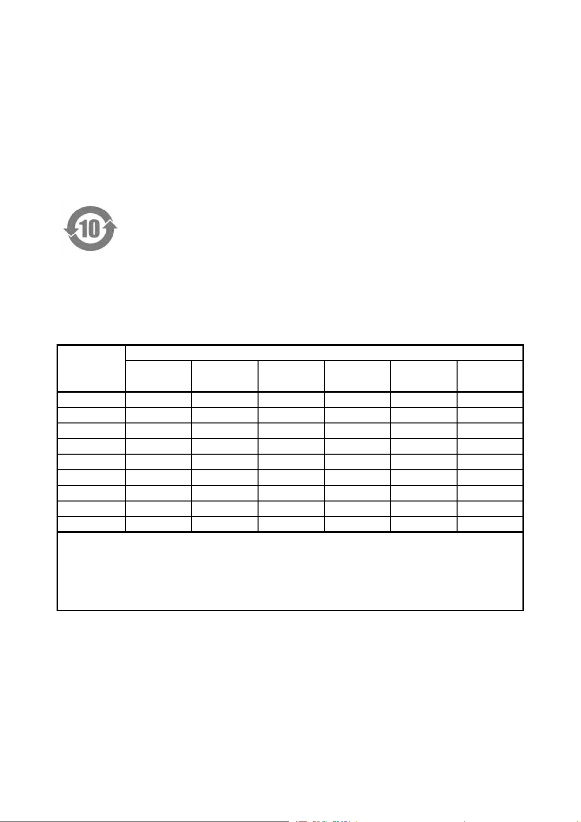
Following information is for Chinese RoHS only
所含有毒有害物质信息
部件号码:
此标志适用于在中国销售的电子信息产品,依据2006年2月28日公布的
《电子信息产品污染控制管理办法》以及SJ/T11364-2006《电子信息产品污染
控制标识要求》,表示该产品在使用完结后可再利用。数字表示的是环境保护使
用期限,只要遵守与本产品有关的安全和使用上的注意事项,从制造日算起在数
字所表示的年限内,产品不会产生环境污染和对人体、财产的影响。
产品适当使用后报废的方法请遵从电子信息产品的回收、再利用相关法令。
详细请咨询各级政府主管部门。
部件名称
Parts 铅 汞 镉 六价铬 多溴联苯 多溴二苯醚
(Pb) (Hg) (Cd) (Cr(Ⅵ)) (PBB) (PBDE)
实装基板 × ○ ○ ○ ○ ○
主体部 × ○ ○ ○ ○ ○
附件 ○ ○ ○ ○ ○ ○
包装材 ○ ○ ○ ○ ○ ○
LV 58SER02
产品中有毒有害物质或元素的名称及含量
有毒有害物质或元素 Hazardous Substances in each Part
备注)
○:表示该有毒有害物质在该部件所有均质材料中的含量均在SJ/T11363-2006 规定的限量要求以下。
×:表示该有毒有害物质或元素至少在该部件的某一均质材料中的含量超出SJ/T11363-2006
标准规定的限量要求。
Ver.5
Page 49

LEADER ELECTRONICS CORP.
2-6-33 Tsunashima-Higashi, Kohoku-ku, Yokohama 223-8505, Japan
PHONE:81-45-541-2123 FAX:81-45-541-2823 http://www.leader.co.jp
Aug. 16, 2010 Ver.4 (FW Ver.6.7)
 Loading...