

Page 1

LV 5800
MULTI MONITOR
INSTRUCTION MANUAL
Page 2

TABLE OF CONTENTS
GENERAL SAFETY SUMMARY ......................................................................................... I
1. INTRODUCTION.......................................................................................................... 1
1.1 Scope of W
1.2 Operating Precautions
1.2.1 Maximum Allowable Input V
1.2.2 Caution at the
1.2.3 Last Memory
1.2.4 Mechanical Shock
1.2.5 LCD Monitor
1.2.6 Flickering of the LCD
1.2.7 About the Cabinet
1.3 About Abandonment
arranty .................................................................................................................... 1
.............................................................................................................. 1
oltage..................................................................................... 1
Time of Standby.......................................................................................... 1
...................................................................................................................... 2
............................................................................................................. 2
...................................................................................................................... 2
......................................................................................................... 2
.............................................................................................................. 2
................................................................................................................. 3
2. ABOUT THIS MANUAL................................................................................................ 4
3. SPECIFICATIONS ....................................................................................................... 5
3.1 General
3.2 Features
3.3 S
pecifications............................................................................................................................ 6
3.3.1 Slot
3.3.2 LCD Display
3.3.3 Screen Capt
3.3.4 Preset
3.3.5 External Ref
3.3.6 External Control Connector
3.3.7 Head
3.3.8 General S
..................................................................................................................................... 5
................................................................................................................................... 5
.................................................................................................................................... 6
...................................................................................................................... 6
ure .................................................................................................................6
s .............................................................................................................................. 6
erence Input...................................................................................................6
............................................................................................... 7
phone Output ............................................................................................................7
pecifications....................................................................................................... 7
4. PANEL DESCRIPTION ................................................................................................ 8
4.1 Front Panel
4.1.1 INPUT
4.1.2 DISPLA
4.1.3 MODE Group
4.1.4 PRESET
4.1.5 Miscellaneous.................................................................................................................. 12
4.2 Rear Panel
4.2.1 Rear Panel Description
4.2.2 L
4.2.3 L
4.2.4 L
4.2.5 L
4.3 Display
............................................................................................................................... 8
Group..................................................................................................................... 8
Y Group................................................................................................................. 9
................................................................................................................... 10
Group ............................................................................................................... 11
.............................................................................................................................. 13
.................................................................................................... 13
V 58SER01A (SDI INPUT) Rear Panel .......................................................................... 15
V 58SER02 (EYE PATTERN Unit) Rear Panel.............................................................. 15
V 58SER40A (DIGITAL AUDIO) Rear Panel.................................................................. 15
V 58SER20 (DVI-I OUTPUT unit) Rear Panel ............................................................... 16
Screen ....................................................................................................................... 16
Page 3

5. INSTALLING THE UNITS........................................................................................... 18
5.1 Remov
5.2 Inst
5.2.1 Inst
5.2.2 Inst
5.2.3 Inst
5.2.4 Installing the LV 58SER04 (MPEG DE
5.2.5 Installing the LV 58SER06 (3G-SDI INPUT)
5.2.6 Installing the LV 58SER07 (EYE P
5.2.7 Installing the LV 58SER20 (DVI OUTPUT unit)
5.2.8 Inst
5.2.9 Installing the LV 58SER40A (DIGITAL AUDIO)
5.3 V
ing the Units ................................................................................................................ 19
alling the Units .................................................................................................................. 20
alling the LV 58SER01A (SDI INPUT)........................................................................ 21
alling the LV 58SER02 (EYE PATTERN unit)............................................................. 21
alling the LV 58SER03 (COMPOSITE VIDEO INPUT) ..............................................26
CODER).............................................................. 26
.................................................................... 26
ATTERN) .................................................................. 27
............................................................... 27
alling the LV 58SER21 (ANALOG COMPONENT OUTPUT)..................................... 27
............................................................... 27
ent Holes .............................................................................................................................. 29
6. OPERATION OVERVIEW .......................................................................................... 30
6.1 Dif
6.1.1 Input Unit
6.1.2 Output Unit
6.1.3 Function Unit
6.1.4 Multipurpose Unit
6.2 Panel Control Basi
6.2.1 Selecting the Display
6.2.2 Selecting the Display
6.2.3 Selecting the Input Signal
6.2.4 Selecting the Display
6.3 Using the T
6.4 V
6.5 V
6.6 Picture Displ
6.7 Audio Display
6.7.1 Displaying the Embedded Audio
6.7.2 Display
6.8 S
6.8.1 S
6.8.2 S
6.9 Ey
6.9.1 L
6.9.2 L
6.10 Menu S
6.10.1 Capture Menu
6.10.2 Sy
6.10.3 Preset Menu
ferences in the Operation by Unit Type .............................................................................. 30
s ....................................................................................................................... 30
s..................................................................................................................... 30
s.................................................................................................................. 30
s........................................................................................................... 30
cs .............................................................................................................. 31
Area............................................................................................... 31
Format........................................................................................... 33
................................................................................................ 33
Mode ............................................................................................. 33
ab Menu................................................................................................................ 34
ideo Signal Waveform Display.............................................................................................. 35
ector Waveform Display........................................................................................................35
ay........................................................................................................................ 36
.......................................................................................................................... 36
...................................................................................... 36
ing the External Audio.......................................................................................... 37
tatus Display......................................................................................................................... 37
tatus Display of SDI Signals .......................................................................................... 37
tatus Display of Audio.................................................................................................... 38
e Pattern Display ................................................................................................................ 38
V 58SER02's Eye Pattern Display ................................................................................. 38
V 58SER07's Eye Pattern Display ................................................................................. 39
tructure ....................................................................................................................... 40
.................................................................................................................. 40
stem Menu................................................................................................................... 41
.................................................................................................................... 43
7. SYSTEM SETUP ....................................................................................................... 44
7.1 Sy
7.2 Setting the L
stem Setting of the Unit ...................................................................................................... 45
V 5800 System ................................................................................................... 45
Page 4

7.2.1 LV 5800 General Settings................................................................................................ 45
7.2.2 Ethernet Parameters Set
7.2.3 Remote Connector Settin
7.2.4 Date and
7.2.5 Display
7.2.6 Shutof
7.2.7 Initialization
Time Settings ................................................................................................... 55
ing the Installed Units........................................................................................... 57
f of LCD Backlight ................................................................................................. 57
...................................................................................................................... 58
up ............................................................................................. 49
g ..............................................................................................51
8. CAPTURE FUNCTION .............................................................................................. 59
8.1 Screen Capt
8.1.1 Screen Capt
8.1.2 Selecting the Screen Capture File
8.1.3 Saving the Screen Capture File
8.1.4 Loading a Screen Capture File
8.1.5 Deleting a Screen Capture File
8.2 Frame Capture
ure ...................................................................................................................... 60
ure Procedure.............................................................................................. 60
................................................................................... 61
....................................................................................... 62
........................................................................................ 62
....................................................................................... 63
....................................................................................................................... 63
9. PRESET FUNCTION ................................................................................................. 64
9.1 Registration of Preset and File Operat
9.1.1 Comment Entry................................................................................................................ 66
9.1.2 Sav
9.1.3 Deleting the Preset
9.1.4 Copy
9.2 Recalling the Preset
ing the Presets ..........................................................................................................67
s ........................................................................................................ 67
ing All Presets Data ................................................................................................. 67
s.............................................................................................................. 68
ion of Preset ............................................................... 65
10. PREVENTING POWER CORD DESCRIPTION ........................................................ 69
10.1 Connecting the Power Cord
10.2 Disconnecting the Power Cord
.................................................................................................... 69
............................................................................................... 70
11. MAINTENANCE......................................................................................................... 71
12. FIRMWARE REVISION HISTORY............................................................................. 72
Page 5
GENERAL SAFETY SUMMARY
■ To Avoid Personal Injury
It is recommended that only qualified personnel with technical knowledge use this instrument only
after reading and fully understanding all functions of the instrument described this instruction
manual.
This instrument is not designed and manufactured for consumers.
If you do not have enough knowledge on electricity, to avoid personal injury and prevent damage to
this product, please be sure to use this product only under the supervision of an engineer who has
sufficient knowledge about electronics.
■ Note about Reading This Manual
Should you find the contents in this manual and any of its technical terms confusing, please feel
free to contact your local LEADER agent.
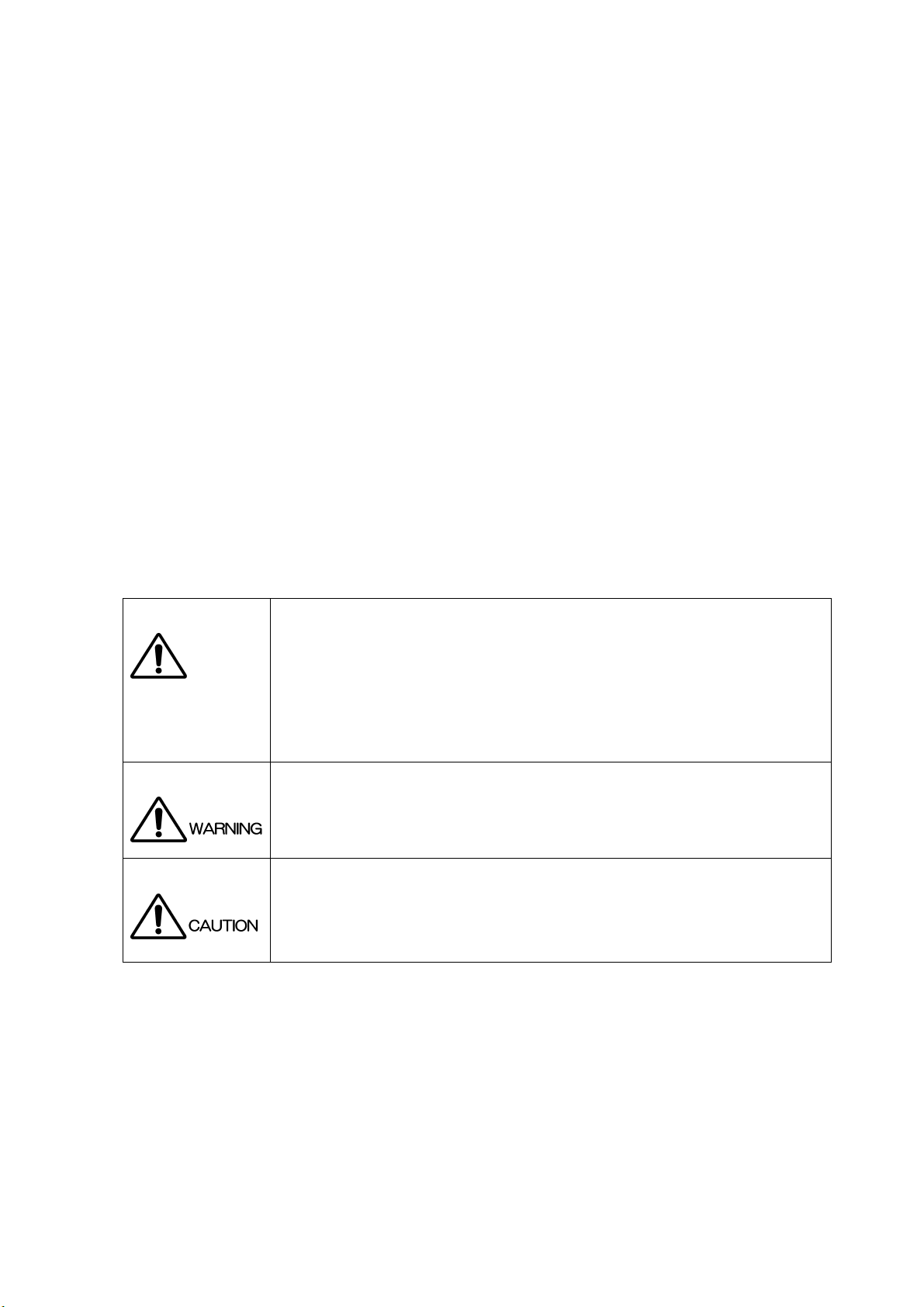
■ Symbols and Terms
Following terms and symbols indicate necessary warnings and cautions used in this manual and on
the product are there for safe operation.
<Symbol>
<Te rm >
The sections where this symbol is marked in this manual or instrument, if not correctly
performed or practiced, could result in personal injury or cause serious danger to the
instrument. Misuse could also produce unintentional movement to create an operational
impediment on the instrument or other products that might be connected to it.
Be sure to refer to the safety precautions in this manual to safely use the part of the
instrument where the symbol is marked.
Warning statements identify warning conditions that if disregarded or not correctly
performed or adhered to, could result in serious personal injury or even loss of life.
<Te rm >
Caution statements identify caution conditions that if disregarded or not correctly
performed or adhered to, could result in personal injury or damage to the instrument.
I
Page 6

GENERAL SAFETY SUMMARY
Review the following safety precautions to avoid operator's injury and loss of life and prevent damage
and deterioration to this instrument.
To avoid potential hazards, use this product as specified.
■ Warnings about the Case and Panels
Operator should not remove any cases or panel of the product other than the time of
exchange of the unit.
Be sure to unplug the LV 5800 from the wall socket before you change the installed units.
If you touch inside the instrument while connecting a power plug to the outlet, it could result
personal shock or fire hazard.
Refrain from spilling any liquid on or inserting anything flammables or piece of metal into the
ventilation of the instrument. Such actions could cause fire, shock, malfunction and be an
accident hazard while the power is on.
■ Warnings about the Power Source
Make sure to connect only to the rated power line voltage. Excess voltage may cause fire.
Confirm the voltage of the commercial power line before connecting the AC power cord.
The voltage range is indicated on the rear panel.
The power frequency of the power line should be 50/60 Hz.
Use a power cord that is appropriate for the voltage of the power source. Also, use a power
cord that meets the safety standards of the country that you are using it in. Using a power
cord that does not meet the standards could lead to fire.
If the attached cord is damaged, stop using it and contact your local LEADER agent. Should
you use a damaged cord, it could cause a shock or create a fire hazard. When you pull out
the cord be sure to hold it by plug and pull from the socket not by holding the cord wire.
II
Page 7

GENERAL SAFETY SUMMARY
Review the following safety precautions to avoid operator's injury and loss of life and prevent damage
and deterioration to this instrument.
To avoid potential hazards, use this product as specified.
■ Warnings about the Installation Environment
●Operating Temperature Range
Operate the instrument between the temperature range of 0 to 40 °C.
Operating the instrument at higher temperatures could cause a fire hazard.
Be sure not to obstruct air circulation.
Rapid changes of temperatures from cold to warm can create internal moisture or
condensation and could damage the instrument.
If there is a possibility of moisture condensation, allows the instrument to sit for 30 minutes
without the power on.
●Operating Humidity Range
Operating humidity range is ≤85 % RH. without condensation
Do not operate the instrument with wet hands. This could cause a shock and fire hazard.
●Operation in the Presence of Gasses
Operating the instrument in and near the presence or storage locations of flammable,
explosive gasses or fumes could create an explosion and fire hazard.
Do not operate the instrument anywhere near such environments.
●Avoid Insertions
Do not insert metals or flammable objects or drop liquid on or into the instrument.
To do so could cause fire, shock, malfunction and create a dangerous accident hazard.
■ If You Notice Something Wrong during Operation
While operating the instrument if smoke, fire, or a bad smell occurs, turn off the instrument at
once for it could cause a fire hazard. When such a case occurs, turn off the power switch and
pull the plug of the cord from the plug socket. Contact your local LEADER agent after
confirming there is no fire.
■ Warning about Grounding
The instrument has a ground terminal to avoid electric shock hazard and to protect the
instrument from damage. Ensure that the product is properly grounded for safe operation.
III
Page 8
GENERAL SAFETY SUMMARY
Review the following safety precautions to avoid operator's injury and loss of life and prevent damage
and deterioration to this instrument.
To avoid potential hazards, use this product as specified.
■ Cautions about the Output Connectors
Do not supply external power to Output terminal, this could cause the instrument to
malfunction. If the cable touches DC power supply etc., there is a possibility that an internal
attenuator might be damaged by a fire.
■ Caution When Not Using the Instrument for a Long Time
Make sure to disconnect the power cord from the socket when you do not use the instrument
for a long time.
■ Routine Maintenance
Avoid the use of thinner or benzene solvents for cleaning cases, panels and knobs since this might
remove the paint or damage plastic surfaces. Wipe cases, panels, and knobs lightly with a soft cloth
damped with neutral detergent. Do not allow water, detergent, or other foreign objects to enter the
instrument while cleaning. Remove the power cord plug from the socket when cleaning the
instrument.
Please conform to the above warnings and cautions for safe operation. There are cautions in each area
of this instruction manual, so please conform to each caution.
If you have any questions about this manual, please feel free to contact your local LEADER agent.
IV
Page 9
1. INTRODUCTION
Thank you for purchasing LEADER’s measuring instruments. Please read this instruction manual
carefully to ensure correct and safe operation.
If you have any difficulties or questions on how to use the instrument after you have read this
manual, please feel free to contact your local LEADER agent. After you have read the manual,
keep the manual in a safe place for quick reference.
1.1 Scope of Warranty
This LEADER instrument has been manufactured under the strictest quality control guidelines.
LEADER shall not be obligated to furnish free service during the warranty period under the
following conditions.
• Repair of malfunction or damages resulting from fire, natural calamity, or improper voltage
applied by the user.
• Repair of an instrument that has been improperly repaired, adjusted, or modified by
personnel other than a factory-trained LEADER representative.
• Repair of malfunctions or damages resulting from improper use.
• Repair of malfunctions caused by devices other than this instrument.
• Repair of malfunctions or damages without the presentation of a proof of purchase or
receipt bill for the instrument.
1.2 Operating Precautions
1. INTRODUCTION
1.2.1 Maximum Allowable Input Voltage
The maximum allowable input voltage to the input connectors is shown in the table below.
Do not apply excessive voltage to prevent damage to the instrument.
Table 1-1 Maximum allowable input voltage
Input Connector Maximum Allowable Input Voltage
REMOTE control connector 0 to +5 V
EXT REF connector ±5 V
1.2.2 Caution at the Time of Standby
Even if LV 5800 turns off the power switch with the front panel, in the state where the power
plug has been connected to the outlet socket, standby state is maintained.
In the state of standby, part of internal circuit is working and it may generate heat.
Therefore, make sure to disconnect the power plug from the outlet when you are not going to
use the LV 5800.
Make sure also to disconnect the power plug from the outlet when you exchange the unit.
Not to do so might cause the instrument to malfunction.
1
Page 10

1.2.3 Last Memory
The LV 5800 has a last-memory feature. When you turn ON the power, the LV 5800 starts up
with the same panel settings that were set when it was last turned OFF.
If the backup battery runs out, the last-memory feature will no longer work, and the internal
clock will be reset. If this happens, contact your local LEADER agent.
To continually use the last-memory and clock features, we recommend that you replace the
backup battery with a new one every five years after you purchase the LV 5800. You cannot
replace the backup battery yourself. To have the battery replaced, contact your local
LEADER agent.
1.2.4 Mechanical Shock
To prevent damage to the precise components used in this instrument, be careful not to
expose the instrument to other forms of severe mechanical shock. If the LCD breaks, grass
fragments may cause injury.
1.2.5 LCD Monitor
1. INTRODUCTION
There may be pixels on the LCD monitor that do not turn ON or those that remain ON at all
times. This is not a malfunction.
1.2.6 Flickering of the LCD
The LCD on the LV 5800 supports many types of video signals. The LCD displays the input
SDI signal asynchronously and may flicker on the waveform display or picture display. The
LV 5800 stores the input SDI signal once to the frame memory, and then reads the memory
using the LCD sync signal, which is asynchronous to the input SDI signal. Therefore, flickers
may occur due to frame skip, which skips over certain frame memories, or frame repeat,
which reads certain frame memories twice.
1.2.7 About the Cabinet
Use a cabinet with one of the specified serial numbers.
Please be aware that you cannot attach the LV 5800 to any of the old cabinets with the serial
numbers listed below.
LR 2404, LR 2427, LR 2427A, LR 2400-AI, LR 2400-AM, LR 2400-VI, LR 2400-VM, and LR
2700-I
2
Page 11

1.3 About Abandonment
Figure 1-1 EU WEEE Directive
The EU WEEE Directive applies to this product and its accessories. When disposing of this
product or its accessories, follow the regulations in your country or region.
(WEEE Directive: Waste Electrical and Electronic Equipment)
Follow the EU Battery Directive when discarding the batteries that you removed from this
instrument.
1. INTRODUCTION
3
Page 12

2. ABOUT THIS MANUAL
2. ABOUT THIS MANUAL
LV 5800 operates as a measuring instrument only when the unit separately prepared by the
option is installed to the LV 5800.
Moreover, the method of operating LV 5800 is different according to the installing situation of the
unit.
In this instruction manual, about the handling of LV 5800 main frame, explains only the portion
which operates in common regardless of the installing situation of each unit.
Please also operate the instrument after well reading and understanding the instructions manual
attached to each installed unit.
In addition, this LV 5800 instruction manual has described assuming that the following units are
installed in LV 5800.
● Input Units
Unit No.1:LV 58SER01A (SDI INPUT)
Unit No.2:LV 58SER01A (SDI INPUT)
Unit No.3:LV 58SER02 (EYE PATTERN unit)
Unit No.4:LV 58SER40A (DIGITAL AUDIO)
● Output Units
Unit No.5:None
Unit No.6:LV 58SER20 (DVI-I OUTPUT unit)
Refer to Figure 4-2, “Rear panel" for the arrangement of the unit number.
4
Page 13

3. SPECIFICATIONS
3.1 General
The LV 5800 is a new concept of multi monitor that allows you freely configure various input
and output units according to your application.
In the digital broadcasting system becoming complicated, you can construct a flexible system
by combining separately prepared input and output units.
3.2 Features
● Four Input Slots
Up to four input units can be installed with arbitrary combination.
Each input unit operates independently.
● Two Output Slots
Up to two output units can be installed with arbitrary combination.
Each output unit operates independently.
● Display Function
3. SPECIFICATIONS
Employs a color TFT LCD monitor with XGA resolution (1024 x 768).
The displaying function of each unit can be displayed on a full screen, or 2 or 4 screen
multi display.
The multi screen display allows arbitrary combination of signals of different input units to
be displayed.
● External Synchronization Signal Input
The video signal waveform display can be displayed matching with the phase of the
external synchronized signal.
● USB Port
Screen captures, data recording, and content of presets can be stored by connecting a
USB memory to the USB connector on the front panel.
● Ethernet Connector
Remote control, error monitoring, and file transfer are possible with using TELNET or FTP
by connecting a PC to the Ethernet connector on the rear panel.
● Remote Connector
The remote connector on the rear panel allows recalling of presets, output of error alarm,
and switching of input channels.
● A Silent Sound Cooling System
Silence FAN is adopted.
By the rotation sensor, it has the function to display the alarm on the screen when FAN
stops due to the breakdown.
Moreover, the rotational speed is controlled with the temperature sensor.
5
Page 14

3.3 Specifications
3.3.1 Slot
Number of Slots for Input 4
Number of Slots for Output 2
3.3.2 LCD Display
LCD Screen Type 6.3-inch TFT color
Display Format XGA (Effective area 1,024x768 dots)
Backlight Brightness Selects HIGH or LOW
Auto Shutoff Sets the time for the backlight to shutoff automatically.
Display Screen 1-screen display, 2-screen display, and 4-screen
3.3.3 Screen Capture
Function Captures the screen
Display Displays the captured image or superimposes the
Media Internal memory (RAM) and USB memory
Data Output Screen captures can be saved as bitmap files or in a
Data Input Data saved to USB memory can be loaded and
* When the unit that is equipped with video signal frame capture function, such as LV 58SER01A (SDI
INPUT), is installed. (switch type of frame capture and screen capture)
3.3.4 Presets
3. SPECIFICATIONS
display
captured image over the input signal
Only one screen capture can be stored in the internal
memory.*
file format that the LV 5800 can load. They can be
saved to USB memory or transmitted over an
Ethernet and saved on a PC.
displayed on the LV 5800.
Number of Presets 60
Media Internal memory (RAM) or a USB memory
Recall Method Through the front panel, remote connector, and
Copy Copies all content of presets to the USB memory or
* Switches between 4 points, 8 points, 15 points, and 60 points for recalling through the remote connector.
3.3.5 External Reference Input
Input Signal Tri-level sync signal or NTSC/PAL black burst
Input Connector BNC connector (1 system 2 connectors)
Input Impedance 15 kΩ (Passive Loop-through)
Input Return Loss ≥ 30 dB 50 kHz to 30 MHz (when power is ON. ≥ 25
Ethernet network
from the USB memory to the LV 5800.
dB when power is OFF)
6
Page 15

Maximum Input Voltage ±5 V (DC + peak AC)
3.3.6 External Control Connector
USB Connector
Specifications USB 2.0
Device Only a USB memory device is supported.
Ethernet Connector
Standard Supported IEEE802.3
Input/Output Connector RJ-45
Function Remote control and errors monitoring, etc. from an
Type 10Base-T/100Base-TX
Remote Connector
Function Recalling of presets, monitoring of errors
Control Signal LV-TTL level (LOW active)
Control Connector 25-pin D-sub (female)
3.3.7 Headphone Output
3. SPECIFICATIONS
external computer
Output Connector 3.5 mm miniature jack 1 connector (stereo)
Function Like LV 58SER40A (DIGITAL AUDIO), it is effective
Output Power 120 mWrms
Impedance 8 Ω
3.3.8 General Specifications
Environmental Conditions
Operating Temperature 0 to 40 °C
Operating Humidity ≤ 85% RH (without condensation)
Spec-Guaranteed Temperature 10 ° to 30 °C
Spec-Guaranteed Humidity ≤ 85% RH (without condensation)
Operating Environment Indoor use
Operating Altitude Up to 2,000 m
Overvoltage Category Ⅱ
Pollution Degree 2
Power Requirements AC 90 V to 250 V, 50Hz/60Hz, 150 W max.
Dimensions 215 (W) x 133 (H) x 449 (D) mm
Weight 5 kg
Accessories nstruction manual ................................... 1
when the unit that has audio decoding function is
inserted.
Power cord ............................................. 1
Cover/Inlet stopper ................................. 1
Screws for rack mounting....................... 2
(inch specification)
D-sub, 25-pin connector ......................... 1
D-sub, 25-pin connector cover ............... 1
7
Page 16
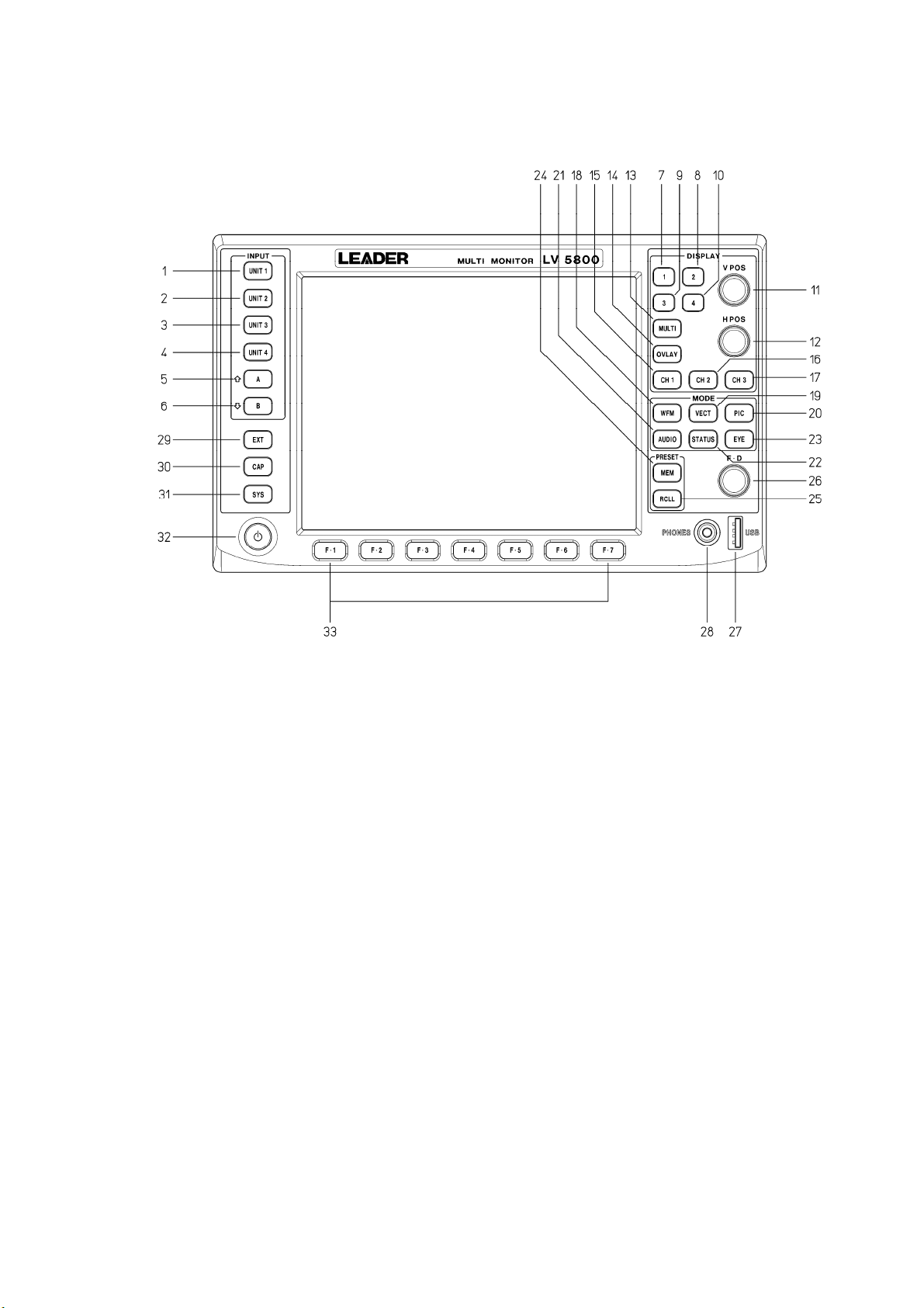
4. PANEL DESCRIPTION
4.1 Front Panel
4. PANEL DESCRIPTION
4.1.1 INPUT Group
(1) UNIT 1 key
Displays the input signal of unit 1 in the selected area.
→ Refer to section 6.2.3, “Selecting the Input Signal”
(2) UNIT 2 key
Displays the input signal of unit 2 in the selected area.
→ Refer to section 6.2.3, “Selecting the Input Signal”
(3) UNIT 3 key
Displays the input signal of unit 3 in the selected area.
→ Refer to section 6.2.3, “Selecting the Input Signal”
(4) UNIT 4 key
Displays the input signal of unit 4 in the selected area.
→ Refer to section 6.2.3, “Selecting the Input Signal”
(5) A Key (A Input Key)
Figure 4-1 Front panel
Displays the A input signal of the selected unit in the selected area.
This key is valid for units that have two inputs (A and B) such as on the LV 58SER01A
(SDI INPUT).
If a unit has three or more input connectors or multiple channels, this key is used as a
8
Page 17

channel selection key. In this case, press this key to decrement the channel number.
→ Refer to section 6.2.3, “Selecting the Input Signal”
(6) B Key (B Input Key)
Displays the B input signal of the selected unit in the selected area.
This key is valid for units that have two inputs (A and B) such as on the LV 58SER01A
(SDI INPUT).
If a unit has three or more input connectors or multiple channels, this key is used as a
channel selection key. In this case, press this key to increment the channel number.
→ Refer to section 6.2.3, “Selecting the Input Signal”
4.1.2 DISPLAY Group
(7) 1 Key (First Area Selection Key)
Press this key on the 4 screen multi display to select the first area at the top left.
Press this key on the 2 screen multi display to show the first area at the top left of the 4
screen multi display expanded in the left half of the screen.
Press this key on the 1 screen display to show the first area at the top left of the 4
screen multi display expanded to full screen.
→ Refer to section 6.2.1, “Selecting the Display Area”
(8) 2 Key (Second Area Selection Key)
4. PANEL DESCRIPTION
Press this key on the 4 screen multi display to select the second area at the top right.
Press this key on the 2 screen multi display to show the second area at the top right of
the 4 screen multi display expanded in the right half of the screen.
Press this key on the 1 screen display to show the second area at the top right of the 4
screen multi display expanded to full screen.
→ Refer to section 6.2.1, “Selecting the Display Area”
(9) 3 Key (Third Area Selection Key)
Press this key on the 4 screen multi display to select the third area at the top right.
Press this key on the 2 screen multi display to show the third area at the bottom left of
the 4 screen multi display expanded in the left half of the screen.
Press this key on the 1 screen display to show the third area at the bottom left of the 4
screen multi display expanded to full screen.
→ Refer to section 6.2.1, “Selecting the Display Area”
(10) 4 Key (Fourth Area Selection Key)
Press this key on the 4 screen multi display to select the fourth area at the bottom right.
Press this key on the 2 screen multi display to show the fourth area at the bottom right of
the 4 screen multi display expanded in the right half of the screen.
Press this key on the 1 screen display to show the fourth area at the bottom right of the
4 screen multi display expanded to full screen.
→ Refer to section 6.2.1, “Selecting the Display Area”
(11) V POS (Vertical Position Control)
Adjusts the vertical display position on the video signal waveform display, eye pattern
display, and other displays.
Press the control to reset the vertical position to the reference.
9
Page 18

4. PANEL DESCRIPTION
(12) H POS (Horizontal Position Control)
Adjusts the horizontal display position on the video signal waveform display, eye pattern
display, and other displays.
Press the control to reset the horizontal position to the reference.
(13) MULTI Key (Multi Display Key)
Switches between 4 or 2 screen multi display and 1 screen display.
The key LED turns on/off each time you press the key. When the key LED is illuminated,
the multi screen display is enabled. Otherwise, 1 screen display is enabled.
→ Refer to section 6.2.2, “Selecting the Display Format”
(14) OVLAY Key (Overlay Display Key)
Switches between overlay and parade display when showing the component video
signal waveforms in the selected area.
The key LED turns on/off each time you press the key. When the key LED is illuminated,
the overlay display is enabled. Otherwise, the parade display is enabled.
You can switch each area on the 4 screen multi display using OVLAY key.
(15) CH1 Key (Channel 1 Selection Key)
Shows or hides the signal assigned to CH1 when displaying the component video signal
waveforms in the selected area.
The key LED turns on/off each time you press the key. When the key LED is illuminated,
the signal assigned to CH1 is shown. Otherwise, the signal is hidden.
You can switch each area on the 4 screen multi display using CH1 key.
(16) CH2 Key (Channel 2 Selection Key)
Shows or hides the signal assigned to CH2 when displaying the component video signal
waveforms in the selected area.
The key LED turns on/off each time you press the key. When the key LED is illuminated,
the signal assigned to CH2 is shown. Otherwise, the signal is hidden.
You can switch each area on the 4 screen multi display using CH2 key.
(17) CH3 Key (Channel 3 Selection Key)
Shows or hides the signal assigned to CH3 when displaying the component video signal
waveforms in the selected area.
The key LED turns on/off each time you press the key. When the key LED is illuminated,
the signal assigned to CH3 is shown. Otherwise, the signal is hidden.
You can switch each area on the 4 screen multi display using CH3 key.
4.1.3 MODE Group
(18) WFM Key (Video Signal Waveform Display Key)
Displays the video signal waveform in the selected area.
You can set the video signal waveform display independently for each area in the 4
screen multi display. A unit with a video signal input is required such as the LV
58SER01A (SDI INPUT).
→ Refer to section 6.4, “Video Signal Waveform Display”
10
Page 19

4. PANEL DESCRIPTION
(19) VECT Key (Vector Waveform Display Key)
Displays the vector signal waveform in the selected area.
You can set the vector signal waveform display independently for each area in the 4
screen multi display.
A unit with a video signal input is required such as the LV 58SER01A (SDI INPUT).
→ Refer to section 6.5, “Vector Waveform Display”
(20) PIC Key (Picture Display Key)
Displays the picture in the selected area.
You can set the picture display independently for each area in the 4 screen multi display.
A unit with a video signal input is required such as the LV 58SER01A (SDI INPUT).
→ Refer to section 6.6, “Picture Display”
(21) AUDIO Key (Audio Display Key)
Displays the audio in the selected area.
The audio display can be shown in any area on the 4 screen multi display, but there is a
limitation to the simultaneous display function.
The LV 58SER40A (DIGITAL AUDIO) that has the audio display function is required.
→ Refer to section 6.7, “Audio Display”
(22) STATUS Key (Status Display Key)
Displays errors and analysis results of the input signal in the selected area.
You can set the status display independently for each area in the 4 screen multi display.
A unit with a digital signal analysis function is required such as the LV 58SER01A (SDI
INPUT).
→ Refer to section 6.8, “Status Display”
* Errors and analysis results of the audio signal or the eye pattern display are shown in the audio
display or eye pattern display.
(23) EYE Key (Eye Pattern Display Key)
Displays the eye pattern in the selected area.
The eye pattern can be shown in any area on the 4 screen multi display, but there is a
limitation to the simultaneous display function.
You need the LV 58SER02 (EYE PATTERN Unit) or LV 58SER07 (EYE PATTERN),
both of which have the eye pattern display feature.
→ Refer to section 6.9, “Eye Pattern Display”
4.1.4 PRESET Group
(24) MEM Key (Memory Key)
Stores the key settings and menu settings of the LV 5800.
→ Refer to section 9.1, “Registration of Preset and File Operation of Preset”
(25) RCLL Key (Recall Key)
Recalls key settings and menu settings that are stored in the LV 5800.
→ Refer to section 9.2, “Recalling the Presets”
11
Page 20

4.1.5 Miscellaneous
(26) F・D (Function Dial)
Sets values or moves the cursor in the menu operation.
Press the dial to reset the value to the reference.
(27) USB (USB Port)
Connect the USB memory to this port. The USB memory can be used to save various
data including analysis data and capture data. The port supports USB 2.0.
(28) PHONES (Headphone Jack)
A miniature jack for connecting a headphone.
The LV 58SER40A (DIGITAL AUDIO) that has the audio function is required.
(29) EXT Key (External Synchronization Setting Key)
Switches the display reference synchronization signal to an external signal or the
synchronization signal of the signal whose waveform is being displayed in the video
signal waveform display shown in the selected area.
The key LED turns on/off each time you press the key. When the key LED is illuminated,
the external synchronization signal is used. Otherwise, the synchronization signal of the
signal whose waveform is being displayed is used.
You can specify the external signal setting independently for each area in the 4 screen
multi display.
A unit with a video signal input is required such as the LV 58SER01A (SDI INPUT).
(30) CAP Key (Capture Key)
4. PANEL DESCRIPTION
Executes a screen capture. The screen capture data can be stored as a bitmap file in a
USB memory. If you save the screen capture data as a BSG file to a USB memory, you
can display the screen image again by loading the file into the LV 5800.
If the LV 58SER01A (SDI INPUT) or LV 58SER06 (3G-SDI INPUT) is installed, you can
store a frame of video data in the internal memory and display it in the video signal
waveform, vector, and picture displays. In addition, the data can be stored to a USB
memory and loaded into the LV 5800 later to be displayed.
→ Refer to chapter 8, “CAPTURE FUNCTION”
(31) SYS Key (System Key)
Specifies system settings and error settings of the LV 5800 main frame or each unit.
→ Refer to chapter 7, “SYSTEM SETUP”
(32) Power Switch
An electronic switch that keeps track of the power on/off state.
* The LV 5800 is maintained in standby mode even if the power switch is turned off.In the state of
standby, it consumes approximately 15 W of power and may generate heat. If you are not going to
use the LV 5800 for an extended time, remove the power plug from the outlet.
(33) F・1 to F・7 (Function Keys)
Used to operate the menu.
12
Page 21
4.2 Rear Panel
4. PANEL DESCRIPTION
Figure 4-2 is an example in which the following units are installed to the LV 5800.
● Input Units
Unit No.1:LV 58SER01A (SDI INPUT)
Unit No.2:LV 58SER01A (SDI INPUT)
Unit No.3:LV 58SER02 (EYE PATTERN unit)
Unit No.4:LV 58SER40A (DIGITAL AUDIO)
● Output Units
Unit No.5:None
Unit No.6:LV 58SER20(DVI-I OUTPUT unit)
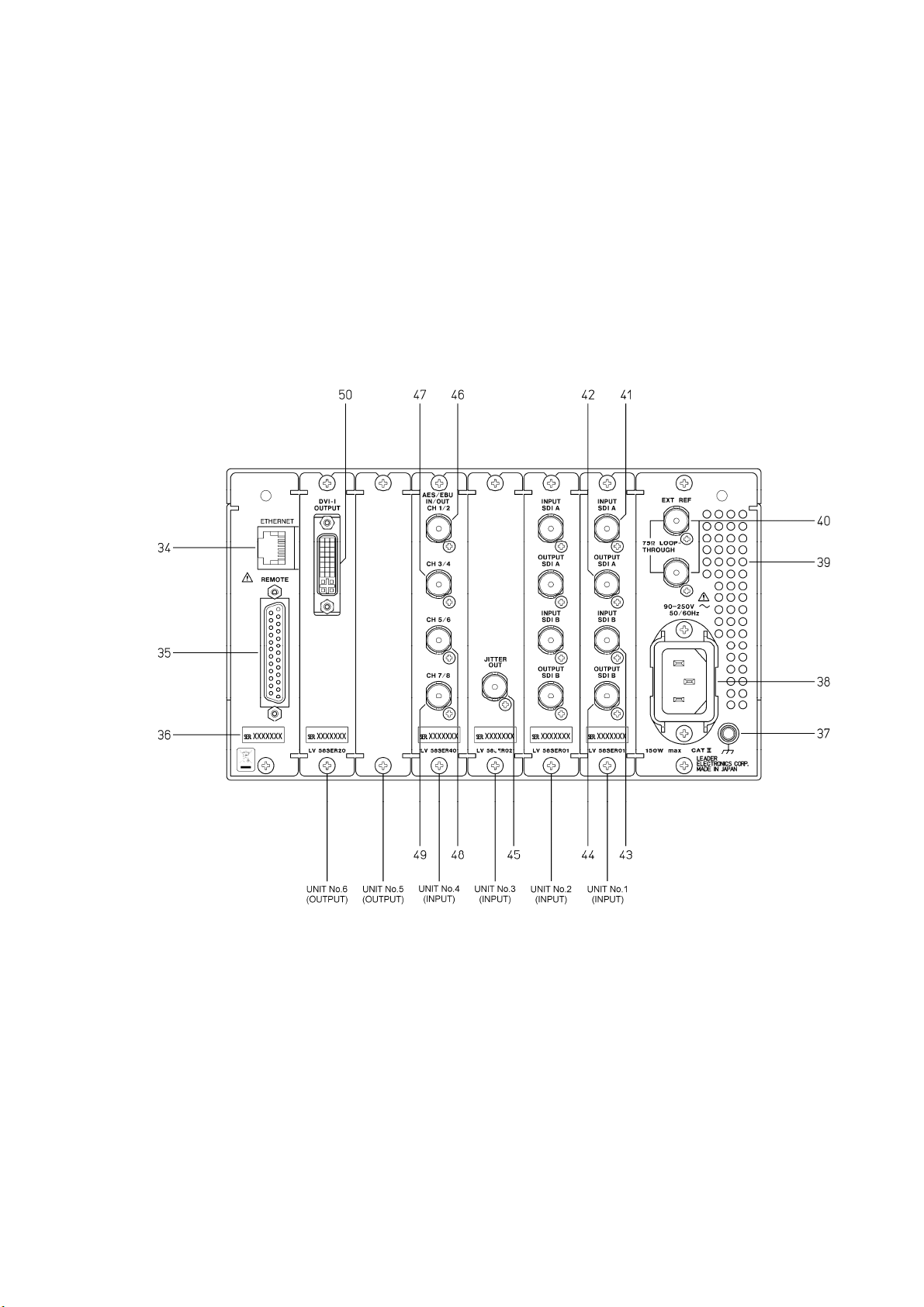
4.2.1 Rear Panel Description
(34) ETHERNET (Ethernet Connector)
Ethernet connector applicable to 100BASE-TX/10BASE-T.
When connecting to the network via a hub, use a straight cable; when directly
connecting to a PC (one-to-one connection), use a cross cable.
→ Refer to section 7.2.2, “Ethernet Parameters Setup”
Figure 4-2 Rear panel
13
Page 22
4. PANEL DESCRIPTION
(35) REMOTE (Remote Connector)
A D-sub, 25-pin remote connector.
Recalls up to 8 or 60 sets of presets.
It can also be used to output errors or switch the input A/B channel.
→ Refer to section 7.2.3, “Remote Connector Setting”
(36) Serial Number
Provide this number when contacting LEADER.
(37) Ground terminal
This terminal is connected to the chassis and is used for grounding.
To prevent electric shock, be sure to ground the LV 5800.
(38) Power Input Terminal
An AC power input connector.
Be sure to use the LV 5800 in the 90 V to 250 V range.
(39) Vent Holes
Vent holes for cooling the LV 5800.
Smoke or fire may result if you use the LV 5800 with the vent holes blocked.
Do not block the vent holes.
→ Refer to section 5.3, “Vent Holes”
(40) EXT REF (External Synchronization Input Connector)
The external synchronization signal input connector for the video signal waveform
display.
The input configuration is loop-through. Terminate the end of the cascade connection at
75 Ω. HDTV tri-level sync signals and NTSC/PAL black burst signals are supported for
the input signal.
Applying excessive input voltage to the connector can cause damage to the instrument.
Pay attention to the maximum input voltage range when applying signals.
The maximum input voltage range of the external synchronization input connector is ±5
V.
14
Page 23

4. PANEL DESCRIPTION
4.2.2 LV 58SER01A (SDI INPUT) Rear Panel
(41) INPUT SDI A (SDI Signal Input A Connector)
(43) INPUT SDI B (SDI Signal Input B Connector)
Input connectors for serial digital signals (SDI).
Each input connector is terminated internally at 75 Ω. Therefore, you do not need to
connect a terminator. Use a cable with a characteristic impedance of 75 Ω for the
connection.
Applying excessive input voltage to the connector can cause damage to the instrument.
Pay attention to the maximum input voltage range when applying signals.
The maximum input voltage range of the SDI input connector is -2 V to +2 V.
(42) OUTPUT SDI A/B (SDI Signal Output A/B Connector)
(44) OUTPUT SDI B (SDI Signal Output B Connector)
Reclocked output of the serial digital signals. The serial digital video signal (SDI) that is
applied to the SDI signal input connectors is output in the state of serial reclocking from
these connectors. Connect the output to an external instrument such as a picture
monitor supporting SDI input. A 75-Ω termination is required at the receiving end.
OUTPUT SDI A/B is the output of INPUT SDI A/B, and OUTPUT SDI B is the output of
INPUT SDI B.
4.2.3 LV 58SER02 (EYE PATTERN Unit) Rear Panel
(45) JITTER OUT (Jitter Output)
Converts the amount of jitter in the serial digital signal (SDI) monitored on the LV
58SER02 to voltage and outputs the voltage.
4.2.4 LV 58SER40A (DIGITAL AUDIO) Rear Panel
(46) AES/EBU IN/OUT CH 1/2 (Digital Audio I/O Connector CH 1/2)
(47) AES/EBU IN/OUT CH 3/4 (Digital Audio I/O Connector CH 3/4)
(48) AES/EBU IN/OUT CH 5/6 (Digital Audio I/O Connector CH 5/6)
(49) AES/EBU IN/OUT CH 7/8 (Digital Audio I/O Connector CH 7/8)
I/O connectors for AES/EBU (digital audio) signals. Switch between input and output
using the system menu.
If the LV 58SER01A (SDI INPUT) or LV 58SER06 (3G-SDI INPUT) is installed and the
LV 58SER40A (DIGITAL AUDIO) is set to output, the embedded audio is extracted from
the selected SDI signal and output as AES/EBU signals.
15
Page 24
4. PANEL DESCRIPTION
Applying an external signal with the digital audio I/O connector set to output may cause
malfunction. Be sure to check the I/O setting before applying an AES/EBU signal.
Applying excessive input voltage to the connector can cause damage to the instrument.
Pay attention to the maximum input voltage range when applying signals.
The maximum input voltage range of the digital audio I/O connector is -5 V to +5 V.
4.2.5 LV 58SER20 (DVI-I OUTPUT unit) Rear Panel
(50) DVI-I OUTPUT (DVI-I Output Connector)
An output connector that supports both TMDS serial digital output and analog RGB
output. The image displayed on the LV 5800 front panel is delivered in DVI-I format.
Connect the output to external equipment such as an external LCD.
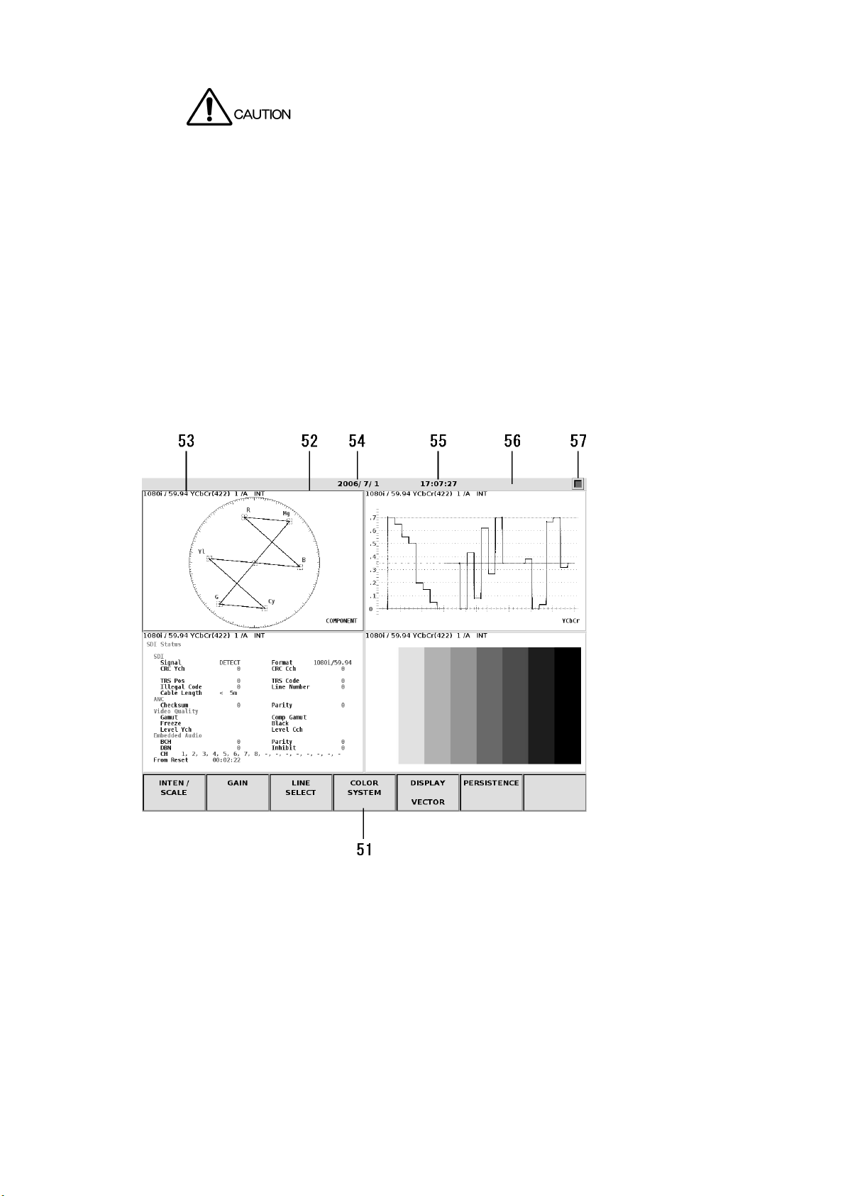
4.3 Display Screen
Figure 4-3 Display screen
16
Page 25

4. PANEL DESCRIPTION
(51) Function Menu
Displays a menu used to carry out various settings. Operate the menu using the F・1 to
F・7 keys or the F・D (function dial).
→ Refer to section 7.2.1, “LV 5800 General Settings”.
(52) Selected Area
Displays the selected area in a blue frame. You can set the frame color by pressing the
SYS key to show the system menu and selecting F・2 (PLATFORM SETUP). Select an
area using the 1 to 4 keys.
(53) Input Signal Status
Indicates the input signal status.
The display varies depending on whether an SDI signal is selected or an audio signal is
selected. For details, see the user’s manual for each unit.
(54) Date
Displays the date. You can set the date by pressing the SYS key to show the system
menu and selecting F・3 (DATE & TIME).
→ Refer to section 7.2.4, “Date and Time Settings”
(55) Time
Displays the current time. You can set the time by pressing the SYS key to show the
system menu and selecting F・3 (DATE & TIME).
→ Refer to section 7.2.4, “Date and Time Settings”
(56) Alarm
Displays alarms. When set to 1 screen display, errors are displayed.
If an error occurs in the internal cooling fan, FAN ALARM is indicated.
If this happens, turn off the power and request repairs.
(57) USB Memory Status
Displays an icon if a USB memory is connected to the USB port.
It is normally green. It turns red while the USB memory is being accessed.
Do not remove the USB memory when the icon is red. It can damage the data or USB
memory.
17
Page 26

5. INSTALLING THE UNITS
5. INSTALLING THE UNITS
It is the customer’s responsibility to install and remove the units appropriately. Damages caused
by the customer’s inadequate handling of the product will be repaired for a fee even if it is within
the warranty period.
The LV 5800 is in standby mode even if the power switch is turned off, and electricity is applied to
the internal circuit. Be sure to remove the power plug from the outlet before installing or removing
units. Otherwise, electric shock or malfunction may result. If the power plug is connected to an
outlet and the power switch on the front panel is OFF, the standby lamp shown in Figure 5-3
blinks.
In case you handle the unit, please wear gloves etc. and do not treat bare-handed. Otherwise, it
may be injured with parts.
Electrostatic discharge may damage the units or the electronic parts of the LV 5800. Follow the
precautions below when installing or removing units.
● Do not perform work in electrically charged locations.
● Wear an antistatic wrist band and gloves to perform work.
● Avoid touching the parts in the units as much as possible.
18
Page 27

5.1 Removing the Units
Remove the top cover to install or remove a unit.
As shown in Figure 5-1, unfastens the 17 screws and removes the top cover.
Three right side screws
Seven rear panel screws
5. INSTALLING THE UNITS
Three top panel screws
Three left side screws
One screw for removing the unit
Figure 5-1 Removing the top cover
Next, gently pull up the red ejector on the front panel of the unit as shown in Figure 5-2.
Using your other hand, pull up on the back side of the unit. Then, slowly pull the unit out.
Figure 5-2 Removing the unit
19
Page 28

5.2 Installing the Units
The units that can be installed in the LV 5800 can be divided into input units and output units.
Input units can be installed in the slots marked Unit No. 1 to 4 (input) in Figure 5-3.
Likewise, output units can be installed in the slots marked Unit No. 5 and 6 (output).
5. INSTALLING THE UNITS
Installing a unit in a wrong position can cause malfunction.
Standby lamp
Circuit board guide
Unit No.1 (input)
Unit No.2 (input)
Unit No.3 (input)
Unit No.4 (input)
Unit No.5 (output)
Unit No.6 (output)
Figure 5-3 Installation position of units
First, check that the circuit board connector pins where the unit is to be connected are not bent
or broken.
Next, slowly slide the unit along the circuit board guide. As shown in Figure 5-4, check that the
circuit board connector of the unit and the circuit board connector of the LV 5800 are aligned
before inserting the unit into the connector.
Figure 5-4 Alignment of the Unit
20
Page 29

5. INSTALLING THE UNITS
After alignment, press both edges of the unit from above as shown in Figure 5-5.
If you feel that the unit is not going in smoothly, pull the unit out and check that the circuit board
connector pins are not bent. Then, install it again.
Figure 5-5 Inserting the unit
Please be careful of the connector on the LV 5800 when inserting or removing a unit. Inserting
or removing a unit at an angle may cause the connector pins to bend which may require the
motherboard to be replaced.
5.2.1 Installing the LV 58SER01A (SDI INPUT)
Install the LV 58SER01A into Units No. 1 to 4 (input) of the LV 5800. The unit will not work if it
is installed in Unit No. 5 or 6 (output).
If you are installing one LV 58SER01A, install it in Unit No. 1 (input). If you are installing
multiple units, install them in order from Unit No. 1 (input) to Unit No. 4 (input). Up to four
units can be installed.
5.2.2 Installing the LV 58SER02 (EYE PATTERN unit)
The LV 58SER02 (EYE PATTERN unit) supports the eye pattern displays up to three of the
LV 58SER01A (SDI INPUT) and LV 58SER04 (MPEG RECODER). To display the eye
pattern, you must connect each other using cables.
Only a single LV 58SER02 can be installed. You cannot install multiple LV 58SER02s. In
addition, you cannot install both the LV 58SER02 and the LV 58SER07 (EYE PATTERN) on
the same LV 5800.
It is preferable that the LV 58SER02 be installed in the next Unit No. (input) after the last LV
58SER01A.
The installation procedure of the LV 58SER02 is given below.
21
Page 30

5. INSTALLING THE UNITS
1. Prepare the LV 58SER02 (EYE PATTERN unit) in a factory default condition as shown
in Figure 5-6. By factory default, a coaxial cable is connected to J2 SDI (ST).
Connected to J2 SDI (ST)
Figure 5-6 LV 58SER02 (EYE PATTERN Unit) in factory default condition
2. To install up to two of the LV 58SER01A and LV 58SER04, connect a cable sold
separately to J3 (OP1) on the LV 58SER02 as shown in Figure 5-7.
Connect an additional cable to J3 SDI (OP1)
Figure 5-7 To install up to two of the LV 58SER01A and LV 58SER04
22
Page 31

5. INSTALLING THE UNITS
3. To install up to three of the LV 58SER01A and LV 58SER04, connect cables sold
separately to J1 (OP2) on the LV 58SER02 as shown in Figure 5-8.
Connect an additional cable to J1 SDI (OP2)
Figure 5-8 To install up to three of the LV 58SER01A and LV 58SER04
4. Install the LV 58SER02 to the LV 5800.
If you have installed one of the LV 58SER01A or LV 58SER04, install the LV 58SER02
to input Unit 2.
If you have installed up to two of the LV 58SER01A and LV 58SER04 together, install
the LV 58SER02 to input Unit 3.
If you have installed up to three of the LV 58SER01A and LV 58SER04 together, install
the LV 58SER02 to input Unit 4.
23
Page 32

5. INSTALLING THE UNITS
5. Remove the LV 58SER01A and LV 58SER04 from the LV 5800, and remove the
terminator.
When the LV 58SER01A is installed, remove the terminator that is attached to J5.
Remove the terminator
Figure 5-9 Terminator attached to the LV 58SER01A
When the LV 58SER04 is installed, remove the terminator that is attached to J4.
Remove the terminator
Figure 5-10 Terminator attached to the LV 58SER04
24
Page 33

5. INSTALLING THE UNITS
6. Connect a coaxial cable to the LV 58SER01A and LV 58SER04.
If you are installing one of the LV 58SER01A or LV 58SER04, connect the connector (*)
of circuit board that is to be installed to Unit 1 to the J2 SDI (ST) on the LV 58SER02.
If you are installing up to two of the LV 58SER01A and LV 58SER04 together, connect
the connector (*) of circuit board that is to be installed to Unit 2 to J3 (OP1) on the LV
58SER02.
If you are installing up to three of the LV 58SER01A and LV 58SER04 together, connect
the connector (*) of circuit board that is to be installed to Unit 3 to J1 (OP2) on the LV
58SER02.
* J5 connector for the LV 58SER01A or J4 connector for the LV 58SER04.
When connecting
the coaxial cable,
be sure to insert
the connector until
Connect a coaxial cable to J5
it clicks in place.
Figure 5-11 Connect a coaxial cable to the LV 58SER01A
Connect a coaxial cable to J4
Figure 5-12 Connect a coaxial cable to the LV 58SER04
25
Page 34

5. INSTALLING THE UNITS
7. Install the LV 58SER01A and LV 58SER04 to the LV 5800, and you are done.
The figure below is the example which installed the LV 58SER01A to Unit No.1 and No.2,
and installed the LV 58SER02 to Unit No.3.
LV 58SER02
LV 58SER01A
LV 58SER01A
Figure 5-13 Install the LV 58SER02 to the LV 5800
5.2.3 Installing the LV 58SER03 (COMPOSITE VIDEO INPUT)
Install the LV 58SER03 into input slots (from Unit No.1 to 4) of the LV 5800. The unit will not
work if it is installed to Unit No. 5 or 6 (output).
When installing one LV 58SER03, install it to Unit No.1 (input).
When installing in sequence with 2, 3 and 4 pieces, install them to Unit No.2 (input), Unit
No.3 (input) and Unit No.4 (input) in order.
It can install it up to four.
5.2.4 Installing the LV 58SER04 (MPEG DECODER)
Install the LV 58SER04 into input slots (from Unit No.1 to 4) of the LV 5800. The unit will not
work if it is installed to Unit No. 5 or 6 (output).
When installing one LV 58SER04, install it to Unit No.1 (input).
In addition, when installing in sequence with 2, 3 and 4 pieces, install them to Unit No.2
(input), Unit No.3 (input) and Unit No.4 (input) in order.
It can install it up to four.
5.2.5 Installing the LV 58SER06 (3G-SDI INPUT)
Install the LV 58SER06 into input slots (from Unit No.1 to 4) of the LV 5800. The unit will not
work if it is installed to Unit No. 5 or 6 (output).
When installing one LV 58SER06, install it to Unit No.1 (input).
In addition, when installing in sequence with 2, 3 and 4 pieces, install them to Unit No.2
(input), Unit No.3 (input) and Unit No.4 (input) in order.
It can install it up to four.
26
Page 35

5. INSTALLING THE UNITS
5.2.6 Installing the LV 58SER07 (EYE PATTERN)
Install the LV 58SER07 into input slots (from Unit No.1 to 4) of the LV 5800. The unit will not
work if it is installed to Unit No. 5 or 6 (output).
Because the LV 58SER07 and LV 58SER06 (3G-SDI INPUT) are used together, we
recommend that you install the LV 58SER07 next to the LV 58SER06.
Only a single LV 58SER07 can be installed. You cannot install multiple LV 58SER07s. In
addition, you cannot install both the LV 58SER02 (EYE PATTERN unit) and the LV 58SER07
on the same LV 5800.
5.2.7 Installing the LV 58SER20 (DVI OUTPUT unit)
Install the LV 58SER20 to Unit No. 5 or 6 (output) of the LV 5800. The unit will not work if it is
installed into input slots (from Unit No.1 to 4).
5.2.8 Installing the LV 58SER21 (ANALOG COMPONENT OUTPUT)
Install LV 58SER21 units into slot number 5 or 6 (the output slots) of the LV 5800. If you
install an LV 58SER21 into a slot from slot number 1 to 4 (the input slots), it will not work.
5.2.9 Installing the LV 58SER40A (DIGITAL AUDIO)
When installing one LV 58SER40A, install it into input slots (from Unit No.1 to 4).
In addition, when installing two LV 58SER40As, you can install only one of them into input
slots (from Unit No.1 to 4) and install other one to Unit No.5 or 6 (output).
When installing three LV 58SER40As, you can install only one of them into input slots (from
Unit No.1 to 4) and install other two to Unit No.5 and 6 (output) respectively.
* You cannot install two or more of LV 58SER40As into input slots (from Unit No.1 to 4).
* Audio signals are not transmitted If the LV 58SER40A is installed only to the Unit 5 or 6 (output).
* If both the LV 58SER40A and the LV 58SER40 are available, install the LV 58SER40A into input slots
(from Unit No.1 to 4).
When the unit installed to the input slots (from Unit No.1 to 4) is LV 58SER40A, LV 5800 and
LV 58SER40A connect by using the analog audio cable of accessories of the LV 58SER40A.
Connect according to the following procedures.
In the case of LV 58SER40, this work is unnecessary.
An analog audio signal cannot be measured in LV 58SER40.
27
Page 36

5. INSTALLING THE UNITS
(1) Connector P12
(3) Connector J3
Figure 5-14 Connection with LV 5800 and LV 58SER40A
1. Connects the cable for analog audio (4 pin-terminal side) to the connector (P12) of a
CPU board.
A CPU board is next to input slot No.6.
When it seems that the situation of Units installed to the input/output slots (from Unit
No.1 to 6) interferes with this work, you can work easy if you remove its Unit once.
Connect so that 1 Pin (brown) of the cable will be the underside. The mark on 1 Pin is
shown to the upper surface of the connector.
Figure 5-15 Connecting the cable to the LV 5800
2. When the Unit installed in the input/output slots (from Unit No.1 to 6) is removed in step
(1), you should return them to the original position again.
3. Connects the cable for analog audio (8 pin-terminal side) to the connector (J3) of the LV
58SER40A.
Connect so that 1 Pin (brown) will become on this side when it views from the front
panel side.
A cable should pass upper side of the input/output slots (from unit No.1 to 6).
28
Page 37

Figure 5-16 Connecting the cable to the LV 58SER40A
5.3 Vent Holes
5. INSTALLING THE UNITS
As shown in Figure 5-17, there are vent holes on the top cover and side and rear panels of the
LV 5800. Do not install the LV 5800 in a way that blocks these vent holes. Otherwise,
malfunction, smoke, or fire may result.
Inlet vent holes
Exhaust vent holes
Figure 5-17 Vent holes
29
Page 38

6. OPERATION OVERVIEW
6. OPERATION OVERVIEW
6.1 Differences in the Operation by Unit Type
This section covers the concepts concerning the operation of each unit of the LV 5800.
The LV 5800 allows the units to be configured freely, but some units have limitations in the
installation or require special operations.
Understanding the concepts concerning the operation will allow you to operate the LV 5800
smoothly if multiple units are installed.
6.1.1 Input Units
The LV 58SER01A (SDI INPUT) is classified as an input unit. The unit has input connectors
that allow you to monitor the input signals.
To monitor the input signal of a unit, select the unit key corresponding to the unit number in
which the unit is installed.
6.1.2 Output Units
The LV 58SER20 (DVI-I OUTPUT unit) is classified as an output unit. Units that only have
output connectors are classified as output units.
There are no unit selection keys for the output units. The output units are configured from the
system menu.
6.1.3 Function Units
The LV 58SER02 (EYE PATTERN unit) is classified as a function unit. The unit does not
have input or output connectors.* The signals needed for monitoring are supplied by other
units. The LV 58SER02 (EYE PATTERN unit) is internally connected to the LV 58SER01A
(SDI INPUT).
Pressing the unit selection key for the unit number in which a function unit is installed
produces no effect. Press the unit selection key of the unit number of the signal source (unit
selection key for the LV 58SER01A), and then press the EYE key.
* The unit outputs the results of jitter measured, but it does not have input or output for the measured
signal.
6.1.4 Multipurpose Units
The LV 58SER40A (DIGITAL AUDIO) is classified as a multipurpose unit. The unit has input
and output connectors as well as an internal connection with the LV 58SER01A (SDI INPUT)
for displaying embedded audio.
On the LV 58SER40A (DIGITAL AUDIO), you can select input or output of the rear BNC
connector using the system menu. If you select input, you can apply AES/EBU signals to the
BNC connector. If you select output, the BNC connector switches to an output connector.
You switch between input unit and output unit by switching the input/output setting of the rear
BNC connector.
30
Page 39

If the rear BNC connector is set to input (if the unit is operating as an input unit), the unit
selection key of the unit number in which the LV 58SER40A (DIGITAL AUDIO) is installed is
enabled. Otherwise, the unit selection key is disabled. The audio signal being displayed is
output as AES/EBU from the rear BNC connector.
To display the embedded audio, press the unit select key of the unit number in which the LV
58SER01A (SDI INPUT) is installed, and then press the AUDIO key. In this case, it does not
matter if the rear BNC connector setting in the system menu is set to input or output.
6.2 Panel Control Basics
This section gives an overview of the LV 5800 panel control.
We recommend that you follow the basic procedures given in this section until you understand
the concept concerning the LV 5800 operation and its limitations.
The LV 5800 may not operate in the same manner as described in this basic procedure
depending on the installation conditions of the units and the system settings of the units. For
details, see the user’s manual for each unit.
6.2.1 Selecting the Display Area
6. OPERATION OVERVIEW
The LV 5800 is basically designed to be used in 4 screen multi display. To start the LV 5800
operation, first select the display area you want to control within the 4 screen multi display.
Select a display area using the 1 to 4 keys.
Figure 6-1 shows the relationship between the keys and the display areas in 4 screen multi
display.
Figure 6-1 Relationship between the area selection keys and the areas in the 4 screen
multi display
31
Page 40

6. OPERATION OVERVIEW
Figure 6-2 shows the relationship between the keys and the display areas in 2 screen multi
display.
Press the 1 or 2 key to show the first and second areas of the 4 screen multi display in the 2
screen multi display.
Press the 3 or 4 key to show the third and fourth areas of the 4 screen multi display in the 2
screen multi display.
The selected area is displayed expanded also in the 1 screen display.
Figure 6-2 Relationship between the area selection keys and the areas in the 2 screen
multi display
32
Page 41

6. OPERATION OVERVIEW
6.2.2 Selecting the Display Format
The LV 5800 has two display formats: multi screen display and 1 screen display.
The multi screen display and 1 screen display switch each time you press the MULTI key.
The MULTI key LED illuminates brightly when multi screen display is enabled.
In addition, multi screen display mode (as shown in Figure 6-3) consists of the 4 screen multi
display and 2 screen multi display.
In case of multi screen display, the switching between 4 screen multi display and 2 screen
multi display can be performed on section 7.2.1, "LV 5800 General Settings".
4 screen multi display 2 screen multi display 1 screen display
Figure 6-3 LV 5800 display formats
6.2.3 Selecting the Input Signal
After selecting the display area, select the input signal. To select the input signal, press the
unit selection key of the unit number to which the signal is being applied. For a unit that has
multiple input connectors such as the LV 58SER01A (SDI INPUT), press the A or B key to
switch the input signal.
6.2.4 Selecting the Display Mode
After selecting the input signal, select the display mode. Select the display mode from the
MODE group. To display the video signal waveform, press the WFM key. Likewise, you can
select vector display, picture display, audio display, eye pattern display, and status display.
If you select a unit that does not support the current display mode, the display mode
automatically changes to WFM. For example, if the current display mode is AUD and you
select a unit that contains the LV 58SER03 (COMPOSITE VIDEO INPUT), the display mode
changes to WFM.
To enter detailed settings of each display, follow the function key menu. For details, see the
user’s manual for each unit.
33
Page 42

6.3 Using the Tab Menu
In addition to the normal pop-up menus, the LV 5800 has tab menus for complex settings as
shown in Figure 6-4. The procedure to operate the tab menu is given below.
6. OPERATION OVERVIEW
Figure 6-4 Tab menu
a) Selecting Items
Turn the F・D to move the cursor indicated by a square. Move the cursor to the item you
want to select and press the F・D to select the check box.
The cursor may not move to certain items in the tab menu depending on the settings of
other items.
b) Setting Values
Some items in the tab menu require a value to be entered such as the error detection level.
Carry out the procedure below to enter values.
Turn the F・D to move the cursor to the item in which a value is to be entered. (You may
not be able to move to the item depending on the setting of other items. If this happens,
check the status of the items above the relevant item.
If you move the cursor to an item in which a value is to be entered, the cursor is filled in
blue.
Press the F・D. The cursor changes from blue to green.
Turn the F・D to select the desired value.
Then, press the F・D to confirm.
c) Moving between Tabs
Normally, you enter settings on multiple tabs in a tab menu. To move between tabs, press
F・2 (PREV) or F・3 (NEXT).
34
Page 43

6. OPERATION OVERVIEW
d) Confirming and Completing the Settings
To confirm and complete the items set in the tab menu, press F・1 (COMPLETE). The
settings are applied, the tab menu closes, and the function menu returns to a higher level.
e) Canceling and Completing the Settings
To cancel and complete the items set in the tab menu, press F・7 (CANCEL). The settings
are not applied, the tab menu closes, and the function menu returns to a higher level.
6.4 Video Signal Waveform Display
Carry out the procedure below to display the SDI video signal waveform that is applied to the
LV 58SER01A (SDI INPUT).
a) Selecting the Display Area
Press the MULTI key to select multi screen display or 1 screen display. If you select multi
screen display, press any of the 1 to 4 keys to select which area in the multi display to
show the video signal waveform.
b) Selecting the Input Signal
Press any of the UNIT 1 to 4 keys to select the unit number in which the LV 58SER01A
(SDI INPUT) is installed. Because the LV 58SER01A (SDI INPUT) has two SDI input
connectors, press the A or B key to select the A or B input.
c) Selecting WFM
Press the WFM key to display the video signal waveform.
The OVLAY key and the CH 1 to 3 keys are enabled in the video signal waveform display.
6.5 Vector Waveform Display
Carry out the procedure below to display the vector waveform of the SDI video signal that is
applied to the LV 58SER01A (SDI INPUT).
a) Selecting the Display Area
Press the MULTI key to select multi screen display or 1 screen display. If you select multi
screen display, press any of the 1 to 4 keys to select which area in the multi display to
show the vector waveform.
b) Selecting the Input Signal
Press any of the UNIT 1 to 4 keys to select the unit number in which the LV 58SER01A
(SDI INPUT) is installed. Because the LV 58SER01A (SDI INPUT) has two SDI input
connectors, press the A or B key to select the A or B input.
c) Selecting VECT
Press the VECT key to display the vector waveform.
If you do not need to change the display area or the input signal, you can simply press the
VECT key to show the vector waveform display.
35
Page 44

6.6 Picture Display
Carry out the procedure below to display the picture of the SDI video signal that is applied to
the LV 58SER01A (SDI INPUT).
a) Selecting the Display Area
Press the MULTI key to select multi screen display or 1 screen display. If you select multi
screen display, press any of the 1 to 4 keys to select which area in the multi display to
show the picture.
b) Selecting the Input Signal
Press any of the UNIT 1 to 4 keys to select the unit number in which the LV 58SER01A
(SDI INPUT) is installed. Because the LV 58SER01A (SDI INPUT) has two SDI input
connectors, press the A or B key to select the A or B input.
c) Selecting PIC
Press the PIC key to display the picture.
If you do not need to change the display area or the input signal, you can simply press the
PIC key to show the picture display.
6.7 Audio Display
6. OPERATION OVERVIEW
This section explains how to display the audio using the LV 58SER40A (DIGITAL AUDIO).
The audio display is divided into the embedded audio display of the LV 58SER01A (SDI
INPUT) and the display of the external audio applied to the digital audio I/O connector on the
rear panel. The procedure to select the input signal is different for each display.
6.7.1 Displaying the Embedded Audio
If the LV 58SER01A (SDI INPUT) and LV 58SER40A (DIGITAL AUDIO) are installed, the
audio embedded in the SDI signal can be displayed.
Carry out the procedure below to display the embedded audio.
a) Selecting the Display Area
Press the MULTI key to select multi screen display or 1 screen display. If you select
multi screen display, press any of the 1 to 4 keys to select which area in the multi display
to show the audio.
b) Selecting the Input Signal
Press any of the UNIT 1 to 4 keys to select the unit number in which the LV 58SER01A
(SDI INPUT) is installed. Because the LV 58SER01A (SDI INPUT) has two SDI input
connectors, press the A or B key to select the A or B input. *
* Do not select the unit number in which the LV 58SER40A (DIGITAL AUDIO) is installed.
c) Selecting AUDIO
Press the AUDIO key to display the audio.
If you are monitoring an SDI signal and you do not need to change the display area or
the input signal, you can simply press the AUDIO key to show the embedded audio
display.
The audio display cannot be shown simultaneously in multiple areas.
36
Page 45

6. OPERATION OVERVIEW
6.7.2 Displaying the External Audio
In addition to displaying the embedded audio, the LV 58SER40A (DIGITAL AUDIO) can also
display an external digital audio signal applied to the rear BNC connector.
Carry out the procedure below to display the external digital audio.
a) Selecting the Input System
To display the external digital audio, you must switch the input/output of the digital audio
I/O connector on the rear panel.
The input/output is switched using the system menu.
First, press the SYS key to display the system menu.
Next, press F・1 (UNIT SETUP) and press the UNIT SETUP function key of the unit
number in which the LV 58SER40A (DIGITAL AUDIO) is installed. The system setup tab
menu of the LV 58SER40A appears.
Turn the F・D to move the cursor to INPUT of External BNC Select in the tab menu.
Press the F・D to select the check box, and press F・1 (COMPLETE) to confirm.
b) Selecting the Display Area
Press the MULTI key to select multi screen display or 1 screen display. If you select
multi screen display, press any of the 1 to 4 keys to select which area in the multi display
to show the audio.
c) Selecting the Input Signal
Press any of the UNIT 1 to 4 keys to select the unit number in which the LV 58SER40A
(DIGITAL AUDIO) is installed. You do not have to press the AUDIO key for the external
digital audio display.
The audio display cannot be shown simultaneously in multiple areas.
6.8 Status Display
This section explains how to show the status display of the various errors that the LV 5800
detects and analysis results. The procedure varies depending on the items that the LV
58SER01A (SDI INPUT) detects and the items that the LV 58SER40A (DIGITAL AUDIO)
detects.
6.8.1 Status Display of SDI Signals
Carry out the procedure below to display the status of the SDI signal that is applied to the LV
58SER01A (SDI INPUT).
a) Selecting the Display Area
Press the MULTI key to select multi screen display or 1 screen display. If you select
multi screen display, press any of the 1 to 4 keys to select which area in the multi display
to show the status.
b) Selecting the Input Signal
Press any of the UNIT 1 to 4 keys to select the unit number in which the LV 58SER01A
(SDI INPUT) is installed. Because the LV 58SER01A (SDI INPUT) has two SDI input
connectors, press the A or B key to select the A or B input.
37
Page 46

c) Selecting STATUS
Press the STATUS key to display the status.
6.8.2 Status Display of Audio
Carry out the procedure below to display the status detected on the LV 58SER40A (DIGITAL
AUDIO).
a) Selecting the Display Area
Press the MULTI key to select multi screen display or 1 screen display. If you select
multi screen display, press any of the 1 to 4 keys to select which area in the multi display
to show the status.
b) Selecting the Input Signal
To display the status of the digital audio that is separated from the embedded audio,
press any of the UNIT 1 to 4 keys to select the unit number in which the LV 58SER01A
(SDI INPUT) is installed.
To display the status of the external digital audio that is applied to the rear BNC
connector of the LV 58SER40A (DIGITAL AUDIO), select the unit number in which the
LV 58SER40A (DIGITAL AUDIO) is installed.
For the LV 58SER01A (SDI INPUT), press the A or B key to select the A or B input,
because the unit has two SDI input connectors.
c) Selecting STATUS
6. OPERATION OVERVIEW
Press the AUDIO key, and press F・2 (DISPLAY MODE) to select STATUS.
6.9 Eye Pattern Display
6.9.1 LV 58SER02's Eye Pattern Display
Carry out the procedure below to display the eye pattern of the SDI signal that is being
measured by the LV 58SER01A (SDI INPUT).
a) Selecting the Display Area
Press the MULTI key to select multi screen display or 1 screen display. If you select
multi screen display, press any of the 1 to 4 keys to select which area in the multi display
to show the eye pattern.
b) Selecting the Input Signal
Press any of the UNIT 1 to 4 keys to select the unit number in which the LV 58SER01A
is installed. Because the LV 58SER01A has two SDI input connectors, press the A or B
key to select the A or B input.
c) Selecting EYE
Press the EYE key to display the eye pattern.
38
Page 47

6. OPERATION OVERVIEW
6.9.2 LV 58SER07's Eye Pattern Display
Carry out the procedure below to display the eye pattern of the SDI signal that is being
measured by the LV 58SER06 (3G-SDI INPUT).
a) Applying the SDI Signal
Apply the SDI signal to an LV 58SER07 INPUT connector.
b) Connecting the Cable between the LV 58SER07 and LV 58SER06
Using the supplied cable, connect the LV 58SER07 OUTPUT A connector to the LV
58SER06 INPUT A connector or the LV 58SER07 OUTPUT B connector to the LV
58SER06 INPUT B connector. Connect one LV 58SER07 to one LV 58SER06. Do not
connect one LV 58SER07 to multiple LV 58SER06s.
c) Selecting the Display Area
Press the MULTI key to select multi screen display or 1 screen display. If you select
multi screen display, press any of the 1 to 4 keys to select which area in the multi display
to show the eye pattern.
d) Selecting the Input Signal
Use the UNIT 1 to 4 keys to select the unit number where the LV 58SER06 (the one that
is connected to the LV 58SER07) is installed. Because the LV 58SER06 has two SDI
input connectors, press the A or B key to select the A or B input.
e) Selecting EYE
Press the EYE key to display the eye pattern.
39
Page 48

6.10 Menu Structure
The structure of the menu is shown below.
Underlined sections indicate initial settings.
6.10.1 Capture Menu
6. OPERATION OVERVIEW
※1
F1 TRIGGER
F3
REFRESH
※2
F4 DISPLAY ( REAL
※3
F4 DISPLAY ( REAL
※4
※6
※4
F5
F6
F7
FILE
SELECT
USB MEM
STORE
USB MEM
RECALL
( MANUAL / ERROR )CAP
/ HOLD / BOTH )
)
※5
F1 BMP FILE
※5
F2 BSG FILE ( ON
※1
F3
※1
F4
※1
F5 FRM FILE ( ON
F7
※7
F1
F3
F7
( ON / OFF )
/ OFF )
DPX FILE ( ON
/ OFF )
TIF FILE ( ON / OFF )
/ OFF )
up
menu
RECALL
FILE
DELETE
F1
F3
up
menu
DELETE
YES
DELETE
NO
*1 Appears when SYS-PLATFORM SETUP-GENERAL SETUP-Capture Mode is set to Video Frame.
*2 Appears when there is screen capture data.
*3 Appears when there is no screen capture data.
*4 Appears when USB memory is connected to the USB port.
*5 Appears when SYS-PLATFORM SETUP-GENERAL SETUP-Capture Mode is set to Screen.
*6 Appears when USB memory is connected to the USB port, there is screen capture data, and one of the
FILE SELECT options is set to ON.
*7 Appears when a BSG or FRM file has been selected.
40
Page 49

6.10.2 System Menu
6. OPERATION OVERVIEW
SYS F1 F1 COMPLETE
UNIT
※1
SETUP
F1
UNIT1
SETUP
※2
※2
F2 PREV
F3 NEXT
F7 CANCEL
※1
F2
UNIT2
F1 COMPLETE
SETUP
※2
F2 PREV
※2
F3 NEXT
F7 CANCEL
※1
UNIT3
F3 F1 COMPLETE
SETUP
※2
F2 PREV
※2
F3 NEXT
F7 CANCEL
※1
UNIT4
F4 F1 COMPLETE
SETUP
※2
F2 PREV
※2
F3 NEXT
F7 CANCEL
※1
UNIT5
F5 F1 COMPLETE
SETUP
※2
F2 PREV
※2
F3 NEXT
F7
※1
UNIT6
F6 F1 COMPLETE
SETUP
※2
F2 PREV
※2
F3 NEXT
CANCEL
41
F7
up
menu
F7 CANCEL
Page 50

6. OPERATION OVERVIEW
F2
※3
F3 DATE&TIME
F5
PLATFORM
SETUP
SYSTEM
INFORMATION
COMPLETE
F1
F2 PREV
F3 NEXT
CANCEL
F7
F1 YEAR
F2 MONTH
DAY
F3
HOUR
F4
F5 MINUTE
SECOND
F6
CLOCK
F7
SET
up
F7
menu
( 1970 - 2038 )
( 1 - 12 )
( 1 - 31 )
( 0 - 23 )
( 0 - 59 )
( 0 - 59 )
F6 LCD OFF
INIT
F7 INITIALIZE
*1 Menu shown when the unit is installed to the LV 5800.
*2 Menu shown when there are multiple tabs.
*3 Appears when PLATFORM SETUP-ETHERNET-Time Server Select is set to OFF.
F1
F3
YES
INIT
CANCEL
42
Page 51

6.10.3 Preset Menu
6. OPERATION OVERVIEW
MEM F1
F2 F1
F3 DELETE F1
※2
F5
COMMENT
INPUT
STORE
ALL COPY
USB->INT
※1
CLEAR
F1
ALL
F2 DELETE
INSERT
F3
F4 <=
F5 =>
CHAR
F6
SET
up
F7
menu
OVER WR
YES
OVER WR
F3
NO
DELETE
YES
DELETE
F3
NO
COPY
F1
YES
COPY
F3
NO
※2
ALL COPY
F6 F1
INT->USB
F3
COPY
YES
COPY
NO
*1 Menu shown when the preset data is in selected No.
*2 Menu shown when a USB memory is connected to the USB port.
43
Page 52

7. SYSTEM SETUP
Settings related to the operation of the entire system are configured from the system menu by
pressing the SYS key.
A system menu can be divided roughly into two as the system setting about LV 5800 main frame,
and the system setting about each unit.
Figure 7-1 SYS key
7. SYSTEM SETUP
Figure 7-2 SYSTEM menu
Table 7-1 System menu description
Function Menu Function
F・1 UNIT SETUP Carries out the system setting of each installed unit.
→ Refer to section 7.1, “System Setting of the Unit”
F・2 PLATFORM SETUP Carries out the system setting of LV 5800 main frame.
→ Refer to section 7.2.1, “LV 5800 General Settings”.
F・3 DATE&TIME Sets the date and time of LV 5800 main frame.
→ Refer to section 7.2.4, “Date and Time Settings”
F・5 SYSTEM INFORMATION Displays the installing situation of LV 5800 main frame and each unit, and
version information.
→ Refer to section 7.2.5, "Displaying the Installed Units."
F・6 LCD OFF The LCD backlight is shutoff and power consumption is lowered.
→ Refer to section 7.2.6, "Shutoff of LCD Backlight
F・7 INITIALIZE Initializes the menu operation.
→ Refer to section 7.2.7, "Initialization."
44
Page 53

7.1 System Setting of the Unit
Press the SYS key to display the system menu. Then, press F・1 (UNIT SETUP) to display
each unit setup menu. Each unit can be set up in this screen.
For details, see the user’s manual for each unit.
7.2 Setting the LV 5800 System
Press the SYS key to display the system menu. Then, press F・2 (PLATFORM SETUP) to
display the tab menu to set up the LV 5800.
From this tab menu, you can set the LV 5800 system setting, Ethernet, remote control, etc.
Each tab menu setting is switched using F・2 (PREV) or F・3 (NEXT).
7.2.1 LV 5800 General Settings
Press the SYS key to display the system menu. Then, press F・2 (PLATFORM SETUP) to
display the tab menu (LV 5800 GENERAL SETUP) to set up the LV 5800.
7. SYSTEM SETUP
Figure 7-3 GENERAL SETUP tab menu
a) Setting the Source Mode and Line Select (Source Mode)
Source Mode in LV 5800 GENERAL SETUP sets whether the input signal displayed in
areas 1 to 4 will be the same (Single Input mode) or different (Multi Input mode). In
Single Input mode, if you change the input unit or input channel in one area, the input
signal will change in all areas.
In addition, the line select function can be synchronized. The selected line is
synchronized between WFM, VECT, PIC, and STATUS (DATA DUMP) display modes.
45
Page 54

7. SYSTEM SETUP
Single Input
Selects Single Input mode. The line select function is
synchronized between display modes and display areas.
If you select a unit that does not support the current
display mode, the display mode automatically changes to
WFM.
Multi Input Selects Multi Input mode. The line select function is not
synchronized.
Multi Input and Line Number Selects Multi Input mode. The line select function is
synchronized between display modes in the same area.
b) Selecting the Number of Multi Display
The item of Multi Display in the LV 5800 GENERAL SETUP tab allows selecting the
display format of the multi screen display.
The display format of the multi screen display of LV 5800 has two screen multi display
and four screen multi display.
2Multi Show the 2 screen multi display when multi display is enabled.
4Multi Show the 4 screen multi display when multi display is enabled.
To switch between multi screen display and 1 screen display use the MULTI key.
→ Refer to section 6.2.2, “Selecting the Display Format”
c) Displaying the Frame of Selected Area (Window Marker)
The Window Marker of LV 5800 GENERAL SETUP can set the frame display of
selected area by using 1 to 4 keys.
OFF Does not display the frame of the selected area.
Blue Displays the frame of the selected area in blue.
White Displays the frame of the selected area in white.
d) Selection of Screen Capture or Frame Capture
The item of Capture Mode in the LV 5800 GENERAL SETUP tab allows selecting the
operation mode of the capture function.
Screen Press CAP key for screen capture mode.
Video Frame Press CAP key for frame capture mode
The capture function of the LV 5800 has a screen capture and a frame capture.
The screen capture function retrieves the contents displayed on the LV 5800 as image
data.
Since the capture is carried out as image data, it cannot process after the capture.
On the other hand, the frame capture is the function which carries out the capture of the
data for one frame of SDI signal.
Since the capture is carried out as frame data, it is possible to process some extent after
the capture.
The frame capture function is enabled when the LV 58SER01A (SDI INPUT) or LV
58SER06 (3G-SDI INPUT) is installed.
Moreover, the screen capture function and the frame capture function cannot be
performed simultaneously.
46
Page 55

7. SYSTEM SETUP
For details of the screen capture, refer to section 8.1, “Screen Capture”.
For details about the frame capture function, see the user's manual of the appropriate
unit.
If the WFM, VECT, PIC, AUD, or EYE key is pressed when the frame capture function
has been selected, the entire screen will blink once.
e) Displaying the Format
The item of Format in the LV 5800 GENERAL SETUP tab allows selecting whether to
display the format of the video signal at the top section of the screen or not to display it.
When having not displayed on the screen about the video signal, it is not displayed even
if the format is set to ON.
f) Displaying the Date
The item of Date in the LV 5800 GENERAL SETUP tab allows setting the date display of
the top section of the screen.
OFF The date is not displayed.
y/m/d The date is displayed in order of the year / month / day.
m/d/y The date is displayed in order of the month / day / year.
d/m/y The date is displayed in order of the day / month / year.
g) Displaying the Time
The item of Time in the LV 5800 GENERAL SETUP tab allows setting the time display of
the top section of the screen.
If the time display is set to OFF and it is made 1 screen display, the time code which can
be displayed by LV 58SER01A (SDI INPUT) etc. will also no longer be displayed.
ON The time is displayed.
OFF The time is not displayed.
h) Displaying the Color System
The item of Color System in the LV 5800 GENERAL SETUP tab allows setting the color
system (YCbCr or RGB, etc.) display of the top section of the screen.
ON The Color System is displayed.
OFF The Color System is not displayed.
The display of the color system shows the type of the inputted video signal.
For example, YCbCr, RGB, etc. are displayed.
Moreover, when the input signal is the video signal, the display of the color system is
displayed.
When external audio is input by the LV 58SER40A (DIGITAL AUDIO), it is not displayed.
47
Page 56

7. SYSTEM SETUP
i) Number Display of Input unit and Display of Input Channel
The item of Input in the LV5800 GENERAL SETUP tab allows setting the display
(number display of input unit and display of input channel) of the top section of the
screen.
Input channel is displayed for units that have two inputs (A and B) such as the LV
58SER01A (SDI INPUT).
ON Number of input unit and input channel are displayed.
OFF Number of input unit and input channel are not displayed.
j) Adjusting the Brightness of the Backlight
The item of Backlight in the LV 5800 GENERAL SETUP tab allows selecting the
brightness of the LCD backlight.
High The LCD back light is made a bright setting.
Low The LCD back light is made a dark setting.
Use the low setting if you are using the LV 5800 in a dark location and
the LCD appears to be too bright.
k) Automatic Shutoff of the Backlight
The item of Auto Off in the LV 5800 GENERAL SETUP tab allows setting the automatic
shutoff of the LCD backlight.
OFF The backlight does not automatically shut off.
5min The backlight is shut off 5 minutes after pressing the last key.
30min The backlight is shut off 30 minutes after pressing the last key.
60min The backlight is shut off 60 minutes after pressing the last key.
If you operate a key while the backlight is OFF, the backlight turns back ON.
* Allow the backlight to turn off and on only a few times per day. Repeating the action frequently
shortens the backlight life.
48
Page 57

7.2.2 Ethernet Parameters Setup
Figure 7-4 Ethernet connector
To connect to the Ethernet network, connects a 100BASE-TX STP cable to the Ethernet
connector.
When connecting to the network via a hub, use a straight cable; when directly connecting to
a PC (one-to-one connection), use a cross cable.
To set up concerning the connection for the Ethernet network, you select the F ・ 2
(PLATFORM SETUP) from the system menu displayed when the SYS key has been
pressed, and display the tab menu (GENERAL SETUP).
Next, pressing the F・3 (NEXT), the LV 5800 ETHERNET SETUP tab menu is displayed, and
Ethernet connection can be set up on this tab.
7. SYSTEM SETUP
Figure 7-5 ETHERNET setup tab menu
49
Page 58

7. SYSTEM SETUP
a) DHCP/IP Selection
The item of Network Select in the LV 5800 ETHERNET SETUP tab allows selecting the
method of the Ethernet connection.
If DHCP is selected in an environment in which a DHCP server is running, the IP
address, subnet mask, and default gateway settings are automatically assigned.
To find out if you can use DHCP, check with your network administrator.
DHCP Set up automatically using DHCP.
IP Set up the IP address by manual operation.
After setting the parameters, power cycle the LV 5800.
b) IP Address Setting
The item of IP Address in the LV 5800 ETHERNET SETUP tab allows setting by manual
the IP address to be assigned to the LV 5800.
At this time, the IP address can be specified when IP is selected in "DHCP/IP
Selection".
The IP address must be a unique number on the network.
For details on obtaining the IP address for the LV 5800, check with your network
administrator.
After setting the IP Address, power cycle the LV 5800.
c) Subnet Mask Setting
The item of Subnet Mask in the LV 5800 ETHERNET SETUP tab allows setting by
manual the Subnet Mask to be assigned to the LV 5800.
At this time, the Subnet Mask can be specified when IP is selected in "DHCP/IP
Selection".
For details on the subnet mask, check with your network administrator.
After setting the subnet mask, power cycle the LV 5800.
d) Default Gateway Setting
The item of Default Gateway in the LV 5800 ETHERNET SETUP tab allows setting by
manual the Default Gateway to be assigned to the LV 5800.
At this time, the Default Gateway can be specified when IP is selected in "DHCP/IP
Selection".
For details on the default gateway, check with your network administrator.
After setting the default gateway, power cycle the LV 5800.
e) Time Server Select Setting
The Time Server Select item in the LV5800 ETHERNET SETUP tab allows you to set
how the date and time are displayed.
50
Page 59

ON The date and time obtained from the time server are displayed. The
protocol used is SNTP.
OFF The date and time that have been set using F・3 (DATE&TIME) in the
system menu are displayed.
F・3 (DATE&TIME) does not appear in the system menu when Time Server Select is set
to ON. If Time Server Select is set to ON but an appropriate connection cannot be
established, “NTP ERROR” is displayed, and the date and time immediately before
Time Server Select was set to ON are displayed. When this happens, the date and time
in screen capture and other files are based on the date and time immediately before
Time Server Select was set to ON.
f) IP Address Setting
The IP Address item in the LV5800 ETHERNET SETUP tab allows you to set the time
server IP address.
IP Address does not appear when Time Server Select is set to OFF.
7.2.3 Remote Connector Setting
7. SYSTEM SETUP
D-sub, 25-pin connector for remote control
Recalls up to 60 points of presets.
The output of an error, and the switch of the input channel and the input unit can also be
performed.
Do not apply external voltage to the output pins.
All input pins are pulled up to +3.3 V.
Do not apply voltage exceeding +5 V or negative voltage when externally controlling the LV
5800.
14 pin
1 pin
Figure 7-6 Rear remote connector
51
Page 60

7. SYSTEM SETUP
Table 7-2 Remote connector pin assignments
Name Input/
Number
1 ALARM1 Output Becomes active when an error is detected.
2 GND GND
3 /CH_A Input Input A is selected. It holds by HIGH.
4 /CH_B Input Input B is selected. It holds by HIGH.
5 N.C. No connection
6 N.C. No connection
7 N.C. No connection
8 N.C. No connection
9 N.C. No connection
10 LCH+ (*1) Input Analog audio signal (Lch+) is applied.
11 LCH- (*1) Input Analog audio signal (Lch-) is applied.
12 RCH+ (*1) Input Analog audio signal (Rch+) is applied.
13 RCH- (*1) Input Analog audio signal (Rch-) is applied.
14 GND GND Ground terminal. It connects when recalling preset.
15 ALARM2 Output Becomes active when an error is detected.
16 ALARM3 Output Becomes active when an error is detected.
17 /P1 Input Preset 1 (recalling bit 1).
18 /P2 Input Preset 2 (recalling bit 2).
19 /P3 Input Preset 3 (recalling bit 3).
20 /P4 Input Preset 4 (recalling bit 4).
21 /P5 Input Preset 5 (recalling bit 5). Unit 1 is selected.
22 /P6 Input Preset 6 (recalling bit 6). Unit 2 is selected.
23 /P7 Input Preset 7 (recalling bit 7). Unit 3 is selected.
24 /P8 Input Preset 8 (recalling bit 8). Unit 4 is selected.
25 ALARM4 Output Becomes active when an error is detected.
Output
When Remote Select is Recall When Remote Select is Unit Select
Ground terminal. It connects when recalling preset.
Function Pin
*1 LV 58SER40A is required for the measurement of an analog audio signal.
The input connectors respond to active-low signals. To configure a setting, apply a stable
signal for at least 350 ms. After configuring a setting, wait at least 1 second before
configuring the next setting.
Figure 7-7 Control timing 1
52
Page 61

7. SYSTEM SETUP
After a setting is made, it may take about 3 seconds for the operation to finish. If you
configure subsequent settings before the initial operation finishes, only the last setting will
take effect. All settings in between will be discarded.
(In the following example, control 2 will be discarded.)
Figure 7-8 Control timing 2
To set up the remote connector, you select the F・2 (PLATFORM SETUP) from the system
menu displayed when the SYS key has been pressed, and display the GENERAL SETUP
tab menu.
Next, the LV 5800 REMOTE SETUP tab menu is displayed pressing the F・3 (NEXT) twice,
and remote connector can be set up on this tab.
Figure 7-9 Remote connector setting tab menu
53
Page 62

7. SYSTEM SETUP
a) Selecting the Preset Recall Mode (Remote Mode)
Remote Mode in LV 5800 REMOTE SETUP is used to select the preset recall mode.
There are two ways to recall a preset. One way is to specify /P1 through /P8 that are
assigned to preset numbers 1 to 8. The other way is to specify a binary number using
/P1 (LSB) through /P6 (MSB) that are assigned to preset numbers 1 to 60.
BIT Recalls a preset number from 1 to 8 that corresponds to /P1 to /P8
(when Remote Select is set to Recall).
Recalls a preset number from 1 to 4 that corresponds to /P1 to /P4
(when Remote Select is set to Unit Select).
BINARY Recalls a preset number from 1 to 60 that is specified in binary code
using /P1 to /P6 (when Remote Select is set to Recall).
Recalls a preset number from 1 to 15 that is specified in binary code
using /P1 to /P4 (when Remote Select is set to Unit Select).
The /P1 to /P8 terminals are low-active logic for both BIT and BINARY modes. To set a
terminal, connect it to ground.
* Once you set the terminals, wait at least 1 second before setting them again.
b) Selecting the Remote Function (Remote Select)
Remote Select in LV 5800 REMOTE SETUP is used to select the function that will be
assigned to /P5 to /P8.
Recall Assigns /P1 to /P8 to be used for recalling presets. Up to 60 presets can
be recalled.
Unit Select Assigns /P1 to /P4 to be used for recalling presets and /P5 to /P8 to be
used for selecting input units. Up to 15 presets can be recalled.
c) Alarm Polarity
The item of Alarm Polarity in the LV 5800 REMOTE SETUP tab allows selecting the
polarity of the signal outputted as an alarm signal when error is detected.
When an error is detected by LV 58SER01A (SDI INPUT) etc., the alarm signal is
outputted as a pulse from alarm pin.
POSITIVE HIGH is outputted at the time of error detection.
NEGATIVE LOW is outputted at the time of error detection.
For the pin number of the alarm output connector, refer to table 7-2, "Remote connector
pin assignments."
d) Alarm Select
The items of Alarm Select from 1 to 4 in the LV5800 REMOTE SETUP tab allow
selecting whether to output as an alarm the error of which input signal into four alarm
output pins respectively.
An input signal is specified by the unit number and, in the case of the unit with two input
of A/B such as LV 58SER01A (SDI INPUT), selection of A, B, and A/B also becomes
effective.
54
Page 63

UNIT1 Outputs the error of unit No.1 as an alarm.
UNIT2 Outputs the error of unit No.2 as an alarm.
UNIT3 Outputs the error of unit No.3 as an alarm.
UNIT4 Outputs the error of unit No.4 as an alarm.
ALL UNIT Outputs the error that occurred on any unit from No. 1 to No. 4 as an
alarm.
A Outputs the error of A channel of the selected unit as an alarm.
B Outputs the error of B channel of the selected unit as an alarm.
A/B Outputs the error of A/B channels of selected unit as an alarm.
* When the unit without two inputs is selected, the setting of A, B, and A/B become invalid.
e) BEEP Select
The item of Error Beep in the LV 5800 REMOTE SETUP tab allows selecting whether to
sound Beep Alarm when error is detected.
ON Sounds the Beep Alarm when error is detected.
OFF Does not sound the Beep Alarm when error is detected.
7.2.4 Date and Time Settings
7. SYSTEM SETUP
The LV 5800 has a calendar and time function. Thus, date/time can be displayed and event
logs can be taken with time information.
You can set up the date and time by pressing the SYS key to show the system menu and
selecting F・3 (DATE&TIME).
Figure 7-10 Date and time setup menu
Table 7-3 Description of date and time setup menu
Function Menu Function
F・1 YEAR Adjusting the year
F・2 MONTH Adjusting the month
F・3 DAY Adjusting the date
F・4 HOUR Adjusting the hour
F・5 MINUTE Adjusting the minute
F・6 SECOND Adjusting the second
F・7 CLOCK SET Date and time confirmation
55
Page 64

a) Adjusting the Year
7. SYSTEM SETUP
[ SYS → F・3 (DATE&TIME) → F・1 (YEAR)]
You can set the year from 1970 to 2038.
From the menu, selects the F・1 (YEAR) and then adjust the year using the function dial
(F・D).
b) Adjusting the Month
[ SYS → F・3 (DATE&TIME) → F・2 (MONTH)]
You can set the month from January to December.
From the menu, selects the F・2 (MONTH) and then adjust the month using the function
dial (F・D).
c) Adjusting the Date
[ SYS → F・3 (DATE&TIME) → F・3 (DAY)]
You can set the date from 1st to 31st.
From the menu, selects the F・3 (DAY) and then adjust the date using the function dial
(F・D).
d) Adjusting the Hour
[ SYS → F・3 (DATE&TIME) → F・4 (HOUR)]
You can set the hour from 1 to 24.
From the menu, selects the F・4 (HOUR) and then adjust the hour using the function dial
(F・D).
e) Adjusting the Minute
[ SYS → F・3 (DATE&TIME) → F・5 (MINUTE)]
You can set the minute from 0 to 59.
From the menu, selects the F・5 (MINUTE) and then adjust the minute using the function
dial (F・D).
Adjusting the Second
f)
[ SYS → F・3 (DATE&TIME) → F・6 (SECOND)]
You can set the second from 0 to 59.
From the menu, selects the F・6 (SECOND) and then adjust the second using the
function dial (F・D).
g) Date and Time Confirmation
[ SYS → F・3 (DATE&TIME) → F・7 (CLOCK SET)]
When you are done adjusting the date and time, press the F・7 (CLOCK SET) to write to
the calendar function of the LV 5800.
The date/time setup menu is closed as the date/time is written, and the screen returns
to the system menu.
To cancel the writing, press the SYS key.
56
Page 65

7.2.5 Displaying the Installed Units
LV 5800 can constitute the unit to install freely. Therefore, in order to use LV 5800 correctly, it
becomes important to understand a setup of the unit installed and each unit.
LV 5800 can confirm the installed unit by confirming the rear panel.
However, because it is built in the Rack etc. and the confirmation is difficult, it can confirm it
from the screen display.
The confirm method from the screen of the installed unit, selects the F・ 5 (SYSTEM
INFORMATION) from the system menu displayed when the SYS key is pressed.
Then, it becomes the following displays, and information about the firmware version of the
LV 5800 main frame and the installed unit will be displayed.
7. SYSTEM SETUP
Figure 7-11 Displaying the installed units
7.2.6 Shutoff of LCD Backlight
You can shut off the LCD backlight by pressing the SYS key to show the system menu and
selecting F・6 (LCD OFF).
If you operate a key while the backlight is OFF, the backlight turns back ON.
* Allow the backlight to turn off and on only a few times per day. Repeating the action frequently shortens
the backlight life.
57
Page 66

7.2.7 Initialization
The LV 5800 stores the last operation before the power is turned off, and starts with the
previous condition when the power is turned on the next time.
To initialize these settings, selects the F・7 (INITIALIZE) from the system menu displayed
when the SYS key has been pressed.
Table 7-4 Initialization menu description
Function Menu Function
F・1 INIT YES Initializes the setting
F・3 INIT CANCEL Cancels the initialization of the setting.
When INIT YES is selected, it is initialized.
If INIT CANCEL has been selected, returns to the system setup menu without initializing.
This initialization procedure does not initialize the date and time, Ethernet settings, content
of presets, settings of remote connector (except for Error Beep), and input/output settings of
BNC connector of LV 58SER40A (DIGITAL AUDIO)
7. SYSTEM SETUP
Figure 7-12 Initialization menu
58
Page 67

8. CAPTURE FUNCTION
The LV 5800 has a capture function that records the screen once as image data in the internal
memory. In addition to simply displaying the image data, this capture function allows overlapping
with the input signal, saving to a USB memory and reloading into the LV 5800 later, and can view
the captured data as bitmap data on a computer.
If the LV 58SER01A (SDI INPUT) or LV 58SER06 (3G-SDI INPUT) is installed, one frame of
video data from the SDI signal can be recorded for each input channel. After capturing the frame
data, it can be shown in different display modes such as video signal waveform display, vector
display, and picture display.
The function that captures the LCD screen as image data is called screen capture on the LV 5800.
The function that captures the video data of one frame of the SDI signal is called frame capture.*
8. CAPTURE FUNCTION
Figure 8-1 CAP key
Figure 8-2 Capture menu
Table 8-1 Capture menu description
Function Menu Function
F・3 REFRESH Acquires new screen capture data.
→ Refer to section 8.1.1, “Screen Capture Procedure.”
F・4 DISPLAY Press to select the captured data display format.
→ Refer to section 8.1.1, “Screen Capture Procedure.”
F・5 FILE SELECT Selects the file to be saved in the USB memory.
→ Refer to section 8.1.2, “Selecting the Screen Capture File.”
F・6 USB MEM STORE Saves captured data to USB memory.
→ Refer to section 8.1.3, “Saving the Screen Capture File.”
F・7 USB MEM RECALL Press to load or delete screen capture data that has been stored to USB memory.
→ Refer to section 8.1.3, “Saving the Screen Capture File.”
59
Page 68

8.1 Screen Capture
The screen capture function retrieves the contents displayed on the LV 5800 as image data.
The captured data can be saved to a USB memory or displayed overlapped with the input
signal.
The capture data is cleared if you press a key other than A, B, EXT, OVLAY, and CH1 to 3 keys
or if you change the display mode such as from the video signal waveform display to the vector
display.
Tab menu, setting screens of preset, and file operation of preset cannot be captured.
8.1.1 Screen Capture Procedure
8. CAPTURE FUNCTION
Carry out the procedure below to capture the screen.
1) Selecting the screen capture function
[SYS→F・2 (PLATFORM SETUP) ]
You select the F・2 (PLATFORM SETUP) from the system menu displayed when the
SYS key has been pressed, and display the GENERAL SETUP tab menu.
Then, selects Screen in the item of Capture Mode on GENERAL SETUP tab.
→Refer to section 7.2.1, “LV 5800 General Settings”.
2) Capture Preparation
Show the display you want to capture and press the CAP key.
3) Starting the Capture Operation
[ CAP → F・3 (REFRESH)]
If the CAP key is pressed, at this time the LV 5800 screen has been captured to the
internal memory. However, when you want to capture the screen again, push the F・3
(REFRESH) key.
4) Selecting the Display
[ CAP → F・4 (DISPLAY) → REAL / HOLD / BOTH ]
To view the screen capture, press F・4 (DISPLAY) to select HOLD. Select BOTH to
display the input signal and the screen capture overlapped. *1
REAL Continues to update the input signal display.
HOLD Displays the screen capture. *2
BOTH Displays the input signal and the still-image data of the screen capture on
top of each other with their intensities halved. *2
*1 In the captured still-image data, video signal waveforms, vector waveforms, audio waveforms, and
eye pattern waveforms are displayed in cyan (except when the waveform color is set to GREEN or
MULTI).
*2 When you specify HOLD or BOTH to check the still-image data, items such as scales, read-outs,
and the 5 bars are not displayed. The draw data is saved as image data if you save the capture
data as a bitmap file to a USB memory.
60
Page 69

8. CAPTURE FUNCTION
8.1.2 Selecting the Screen Capture File
The screen capture is cleared if you change the display mode or turn the power OFF.
However, you can save the screen capture to a USB memory to be displayed even after the
power is turned OFF. You can also view the bitmap data on your computer.
You cannot display the same screen capture file on both the LV 5800 and a PC, because the
file type that can be displayed by the LV 5800 is different than the file type that can be
displayed by a PC. Save screen capture files to the appropriate format depending on your
needs.
The file size of both bitmap and BSG files is approximately 2.4 MB.
Figure 8-3 File selection menu
Table 8-2 File selection menu description
Function Menu Function
F・1 BMP FILE Selects whether to save the bitmap file to the USB memory.
F・2 BSG FILE Selects whether to save the BSG file to the USB memory.
a) Selecting the Bitmap File
[ CAP → F・5 (FILE SELECT) → F・1 (BMP FILE) → ON / OFF ]
By saving the screen capture data as a bitmap file to a USB memory, you can view the
data on your computer.*
Bitmap files cannot be used to redraw the data on the LV 5800. Use BSG files.
To save the bitmap file to the USB memory, press F・5 (FILE SELECT) from the capture
menu and press F・1 (BMP FILE) to select ON.
If you select OFF, the bitmap file is not saved to the USB memory.
* The draw data such as the scale, readout, and audio level waveform are also saved to the bitmap
file in the condition when the screen is captured.
b) Selecting the BSG File
[ CAP → F・5 (FILE SELECT) → F・2 (BSG FILE) → ON / OFF ]
You must save the data as a BSG file to save the screen capture data to a USB memory
once and redraw the data on the LV 5800 later.*
To save the BSG file to a USB memory, press F・5 (FILE SELECT) from the capture
menu and press F・2 (BSG FILE) to select ON.
If you select OFF, the BSG file is not saved to the USB memory.
* Bitmap files cannot be redrawn on the LV 5800. If the data saved as a BSG file is redrawn on the LV
5800, draw data such as the scale, readout, and audio level waveform is not reproduced. The
settings and values that are present when the data is redrawn are used for the draw data.
61
Page 70

8. CAPTURE FUNCTION
8.1.3 Saving the Screen Capture File
[ CAP → F・6 (USB MEM STORE) ]
To save screen capture data to USB memory, connect a USB memory device to the USB
port,* and press F・6 (USB MEM STORE) in the capture menu.
F・6 (USB MEM STORE) will not appear if USB memory is not connected or if all of the
options for F・5 (FILE SELECT) are set to OFF.
Captured data is saved to the USB memory “BMP” folder using the following naming format:
yyyymmddhhmmss (The order is: year, month, day, hour, minute, second. You can set the
date and time in the system settings.)
While screen capture data is being saved to USB memory, the USB mark in the upper right
of the screen changes from green to red, and the message “Saving file” appears at the top of
the screen. Do not remove the USB memory or turn off the power while data is being saved.
It takes approximately five seconds to save a file.
* After USB memory has been connected, it takes the LV 5800 approximately five seconds to recognize it.
8.1.4 Loading a Screen Capture File
[ CAP → F・7 (USB MEM RECALL) → F・1 (RECALL) ]
BSG files stored in a USB memory can be loaded into the LV 5800 to be redrawn. Connect a
USB memory containing BSG files, (*1) and turn the F・D from the capture menu to move the
cursor to the BSG file you want to load. (*2) Then, press F・1 (RECALL) to load the capture
file from the USB memory.
To draw the capture data, press F・4 (DISPLAY) from the capture menu to select HOLD or
BOTH.
→ Refer to section 8.1.1, “Screen Capture Procedure.”
*1 It takes approximately 5 seconds for the LV 5800 to automatically detect the USB memory after it is
connected.
*2 Bitmap files cannot be redrawn on the LV 5800.
62
Page 71

8. CAPTURE FUNCTION
Figure 8-4 Capture file list display and capture file operation menu
Table 8-3 Capture file operation menu description
Function Menu Function
F・1 RECALL Loads a screen capture file that has been saved to USB memory.
F・1 RECALL only appears when the cursor is on a file that can be loaded.
F・3 FILE DELETE Deletes a screen capture file.
→ Refer to section 8.1.5, “Deleting a Screen Capture File”
8.1.5 Deleting a Screen Capture File
[ CAP → F・7 (USB MEM RECALL) → F・3 (FILE DELETE)]
To delete a capture file stored in a USB memory, connect the USB memory containing the
capture file, and turn the F・D from the capture menu to move the cursor to the file you want
to delete. Next, press F・3 (FILE DELETE) to display F・1 (DELETE YES) and F・3 (DELETE
NO). Press F・1 (DELETE YES) to delete the file. Press F・3 (DELETE NO) to cancel the
delete operation.
8.2 Frame Capture
The frame capture function captures the data of one frame of an SDI signal that is applied to
the LV 58SER01A (SDI INPUT) or LV 58SER06 (3G-SDI INPUT). The data can be stored to a
USB memory or displayed overlapped with the input signal. The memory data is not cleared
even if you change the display mode such as from the video signal waveform display to vector
or picture display, and each display can be shown as image data.
However, the frame capture function cannot show the audio display, status display, and eye
pattern display using the capture data.
For details, see the user's manual of the appropriate unit.
63
Page 72

9. PRESET FUNCTION
You can register up to 60 sets of settings on the LV 5800 and recall them later.
The recalling method of stored data can perform operation from the remote connector of the rear
panel besides operation by the front panel.
Since the entire stored presets data can copy collectively to the USB memory, two or more LV
5800 can be used as the same setting.
The LV 5800 cannot register the date and time, Ethernet connection settings, remote control
settings, LV 58SER01A (SDI INPUT) or LV 58SER06 (3G-SDI INPUT) frame capture mode, or
input and output settings for the LV 58SER40A (DIGITAL AUDIO) BNC connector.
If you change the installation configuration of the units in the preset condition, the settings on the
units that have been changed are reset to default values.
9. PRESET FUNCTION
Figure 9-1 MEM key and RCLL key
64
Page 73

9. PRESET FUNCTION
9.1 Registration of Preset and File Operation of Preset
As a registration procedure of preset, it sets as the state where you want to register LV 5800
first. Next, since a preset entry menu will be displayed if the MEM key is pressed, performs in
the following procedure.
Figure 9-2 Entry Screen of Preset and Entry Menu of Preset
Table 9-1 Preset entry menu description
Function Menu Function
F・1 COMMENT INPUT Enters comments for presets data.
→ Refer to section 9.1.1 “Comment Entry”
F・2 STORE Stores the presets data.
→ Refer to section 9.1.2 “Saving the Presets”
F・3 DELETE Clears the presets data.
→ Refer to section 9.1.3 “Deleting the Presets”
F・5 ALL COPY USB->INT Copies all the presets data to the USB memory.
→ Refer to section 9.1.4 “Copying All Presets Data”
F・6 ALL COPY INT->USB Copies all the presets data stored on the USB memory to the LV 5800.
→ Refer to section 9.1.4 “Copying All Presets Data”
65
Page 74

9.1.1 Comment Entry
r
9. PRESET FUNCTION
[ MEM → F・1 (COMMENT INPUT)]
A comment can be entered into presets data to 20 characters for each preset number.
To enter a comment, press the F・1 (COMMENT INPUT) from the memory menu to display
the comment entry screen.
Since the file name entry screen as shown in Figure 9-3 is displayed, enter the file name
using the function dial (F.D) and the function key.
When the function dial (F.D) has been turned, the character selection cursor moves.
Then, pressing the F・D, the character shown with the character selection cursor is applied to
the file name.
After the comment has been entered, press the F・7 (up menu) to return to the preset entry
menu.
Character selection cursor
File name curso
Figure 9-3 Comment entry screen of preset and comment entry menu of preset
Table 9-2 Comment entry menu description
Function Menu Function
F・1 CLEAR ALL Deletes the entire displayed file name.
F・2 DELETE Deletes a character from the file name.
F・3 INSERT Inserts a single space to the file name.
F・4 <= Moves the file name cursor to the left by a character.
F・5 => Moves the file name cursor to the right by a character.
F・6 CHAR SET Applies the character indicated by the character selection cursor to the file name.
You can copy the name of an existing file. To copy a file name, move the cursor to the file
name you want to copy on the entry screen of preset file list screen shown in Figure 9-2, and
press F・D.
66
Page 75

9.1.2 Saving the Presets
9. PRESET FUNCTION
[ MEM → F・2 (STORE)]
Turns the function dial (F.D) and selects the number to which you want to register the presets.
Then, press the F・2 (STORE) to register the presets.
The date, time and file size which were registered are displayed together with a comment.
9.1.3 Deleting the Presets
[ MEM → F・3 (DELETE) → F・1(DELETE YES)]
To delete data that have been registered as a preset, turns the function dial (F.D) on the
entry menu of preset to select the preset data you wish to delete.
Then, press the F・3 (DELETE).
If the confirming screen is displayed, press the F・1 (DELETE YES). When canceling, press
the F・3 (DELETE NO).
9.1.4 Copying All Presets Data
If you wish to make the same presets data on multiple LV 5800 monitors, you can copy entire
presets data using the USB memory (*).
The unit installation configuration of the LV 5800s between which the preset data is to be
copied must be the same. If the unit configuration is different, the preset data is copied only
among the same units installed to the same unit numbers.
* Use FAT16 for the file system on the USB memory.
The one formatted by other file systems cannot be recognized.
a) Copying from USB to LV 5800
[ MEM → F・5 (ALL COPY USB->INT) → F・1 (COPY YES)]
To copy the presets data recorded in the USB memory to the LV 5800, press the F・5
(ALL COPY USB -> INT) from the preset entry menu.
Copies them pressing the F・1 (COPY YES) on the confirming screen.
When canceling, press the F・3 (COPY NO).
b) Copying from LV 5800 to USB memory
[ MEM → F・6 (ALL COPY INT->USB) → F・1 (COPY YES)]
To copy the presets data recorded in the LV 5800 to the USB memory, press the F・6
(ALL COPY INT -> USB) from the preset entry menu.
Copies them pressing the F・1 (COPY YES) on the confirming screen.
When canceling, press the F・3 (COPY NO).
67
Page 76

9.2 Recalling the Presets
Figure 9-4 Menu of recalling presets
Press the RCLL key to display the recall menu. You can recall stored presets data from this
menu.
Since the registration number and the comment are displayed on the function menu, press
each function key.
If there are more than six sets of stored settings, press F・7 (more) to display following seven
data.
Also can move the preset number by turning the function dial (F·D).
9. PRESET FUNCTION
68
Page 77

10. PREVENTING POWER CORD DESCRIPTION
10. PREVENTING POWER CORD DESCRIPTION
To prevent power cord disconnection from the AC inlet, the Cover/Inlet stopper is supplied with
the instrument. Refer to the procedure below.
10.1 Connecting the Power Cord
(1) Insert the power cord connector into the AC inlet.
Base
Connector
(2) Place the Cover/Inlet stopper on top of the connector as shown below.
Cover/Inlet stopper
(3) Press the cover until it clicks into place.
(4) Confirm that the Cover/Inlet stopper is locked to the base.
69
Page 78

10. PREVENTING POWER CORD DESCRIPTION
10.2 Disconnecting the Power Cord
(1) Press the levers on the Cover/Inlet stopper with your fingers to release the lock.
Cover/Inlet stopper (side view)
(2) Remove the Cover/Inlet stopper from the base.
Cover/Inlet stopper
(3) Disconnect the power cord connector from the AC inlet.
Base
Connector
70
Page 79

11. MAINTENANCE
This instrument is produced under the strictest quality controls at the factory, but accuracy may
gradually deteriorate due to worn components.
Therefore, periodic calibration should be performed.
Moreover, if troubles etc. are found in operation, the repair is needed.
When service or calibration is required, contact your local LEADER agent.
11. MAINTENANCE
71
Page 80

12. FIRMWARE REVISION HISTORY
12. FIRMWARE REVISION HISTORY
This manual was written for firmware version 6.8.
To confirm the version, press a key in order of SYS => F・5 SYSTEM INFORMATION.
● Ver 4.8
・ The LV 5800 now supports SNTP and can display the date and time obtained from a time
server.
● Ver 4.7
・ Improvements have been made so that screen capture data can be saved to USB
memory with two actions. File names are now automatically generated combinations of
the date and time.
● Ver. 3.7
● Ver. 3.4
・ The single input mode is added to the LV 5800.
・ The input unit of the LV 5800 can be remotely controlled via the remote connector on the
・ The beeper on the LV 5800 sounds if an error occurs.
● Ver. 3.1
rear panel.
・ The window frame color can be changed.
● Ver. 1.6
・ The frame capture function is added.
・ The current COLOR SYSTEM can be displayed in the WAVEFORM display mode.
・ The display on/off function is added for the time, input information, and so on.
・ The frame can be erased in the single screen mode.
・ The PLATFORM TAB menu is added to the SYSTEM.
・ The MULTI menu is moved to the SYSTEM menu.
72
Page 81

Index
—A—
Alarm Polarity................................................ 54
Alarm Select.................................................. 54
ALL COPY INT->USB ................................... 67
ALL COPY USB->INT ................................... 67
AUDIO ...........................................................11
—B—
Multi Display.................................................. 46
—N—
Network Select .............................................. 50
—P—
PIC ................................................................ 11
PLATFORM SETUP ...................................... 45
BMP FILE...................................................... 61
BSG FILE...................................................... 61
—C—
CAP .............................................................. 12
Capture Mode ............................................... 46
Color System ................................................ 47
COMMENT INPUT........................................ 66
—D—
Date .............................................................. 47
DATE&TIME.................................................. 55
Default Gateway ........................................... 50
DELETE........................................................ 67
DISPLAY ....................................................... 60
DVI-I OUTPUT .............................................. 16
—E—
Error Beep .................................................... 55
ETHERNET................................................... 13
EYE................................................................11
—R—
RCLL ............................................................. 11
RECALL ........................................................ 62
REFRESH ..................................................... 60
REMOTE....................................................... 14
Remote Mode................................................ 54
Remote Select............................................... 54
—S—
Source Mode................................................. 45
STATUS......................................................... 11
STORE.......................................................... 67
Subnet Mask ................................................. 50
SYS ............................................................... 12
SYSTEM INFORMATION.............................. 57
—T—
Time .............................................................. 47
Time Server Select........................................ 50
—U—
—G—
GENERAL SETUP........................................ 45
—I—
INITIALIZE .................................................... 58
Input.............................................................. 48
IP Address................................................50, 51
—M—
MULTI ........................................................... 10
USB MEM RECALL....................................... 62
USB MEM STORE ........................................ 62
—V—
............................................................. 11
VECT
—W—
WFM.............................................................. 10
Window Marker .............................................46
Page 82

Following information is for Chinese RoHS only
所含有毒有害物质信息
部件号码:
此标志适用于在中国销售的电子信息产品,依据2006年2月28日公布的
《电子信息产品污染控制管理办法》以及SJ/T11364-2006《电子信息产品污染
控制标识要求》,表示该产品在使用完结后可再利用。数字表示的是环境保护使
用期限,只要遵守与本产品有关的安全和使用上的注意事项,从制造日算起在数
字所表示的年限内,产品不会产生环境污染和对人体、财产的影响。
产品适当使用后报废的方法请遵从电子信息产品的回收、再利用相关法令。
详细请咨询各级政府主管部门。
部件名称
Parts 铅 汞 镉 六价铬 多溴联苯 多溴二苯醚
实装基板 × ○ ○ ○ ○ ○
主体部 × ○ ○ ○ ○ ○
液晶显示模组 ○ × ○ ○ ○ ○
开关电源 × ○ ○ ○ ○ ○
风扇 × ○ ○ ○ ○ ○
外筐 ○ ○ ○ ○ ○ ○
线材料一套 ○ ○ ○ ○ ○ ○
附件 ○ ○ ○ ○ ○ ○
包装材 ○ ○ ○ ○ ○ ○
电池 ○ ○ ○ ○ ○ ○
有毒有害物质或元素 Hazardous Substances in each Part
(Pb) (Hg) (Cd) (Cr(Ⅵ)) (PBB) (PBDE)
LV 5800
产品中有毒有害物质或元素的名称及含量
备注)
○:表示该有毒有害物质在该部件所有均质材料中的含量均在SJ/T11363-2006 规定的限量要求以下。
×:表示该有毒有害物质或元素至少在该部件的某一均质材料中的含量超出SJ/T11363-2006
标准规定的限量要求。
Ver.6
Page 83

LEADER ELECTRONICS CORP.
2-6-33 Tsunashima-Higashi, Kohoku-ku, Yokohama 223-8505, Japan
PHONE:81-45-541-2123 FAX:81-45-541-2823 http://www.leader.co.jp
Sep. 14, 2010 Ver.11 (FW Ver.6.8)
 Loading...