

Leader LV7300-SER01, LV7300, LV5350-SER11, LV5300-SER11, LV5300-SER12 Instruction Manual
...Page 1

LV5300 / LV5350 / LV7300
WAVEFORM MONITOR / RASTERIZER
LV7300-SER01 SDI INPUT
LV7300-SER02 SDI INPUT / EYE
LV5300-SER11 / LV5350-SER11 BATTERY ADAPTER V MOUNT
LV5300-SER12 / LV5350-SER12 BATTERY ADAPTER QR GOLD
LV5300-SER20 / LV5350-SER20 / LV7300-SER20 AUDIO
LV5300-SER21 / LV5350-SER21 / LV7300-SER21 CLOSED CAPTION
LV5300-SER22 / LV5350-SER22 / LV7300-SER22 CIE
LV5300-SER23 / LV5350-SER23 / LV7300-SER23 HDR
LV5300-SER24 / LV5350-SER24 / LV7300-SER24 TSG
LV5300-SER25 / LV5350-SER25 / LV7300-SER25 FOCUS ASSIST
LV5300-SER26 / LV5350-SER26 / LV7300-SER26 LAYO U T
LV5300-SER27 / LV5350-SER27 / LV7300-SER27 TALLY
LV5300-SER28 / LV5350-SER28 / LV7300-SER28 4K
Instruction Manual
Thank you for purchasing.
Please carefully read this instruction manual and the included "GENERAL SAFETY SUMMARY".
Please use the product safely.
Page 2

TABLE OF CONTENTS
GENERAL SAFETY SUMMARY .................................................................................. I
1. INTRODUCTION ............................................................................................ 1
1.1 Scope of Warranty .................................................................................................... 1
1.2 Operating Precautions ............................................................................................... 1
1.2.1 Maximum Allowable Input Voltage ........................................................................ 1
1.2.2 Mechanical Shock ............................................................................................... 2
1.2.3 Electrostatic Damage .......................................................................................... 2
1.2.4 Warming Up ...................................................................................................... 2
1.2.5 About Standby Mode .......................................................................................... 2
1.2.6 Backup ............................................................................................................. 2
1.2.7 About the LCD Panel (LV5300/LV5350) ................................................................. 2
1.3 About Trademarks and Licenses ................................................................................. 3
1.4 Terminology Used in This Manual ................................................................................ 3
2. PRODUCT CONFIGURATION ............................................................................ 5
2.1 Lineup .................................................................................................................... 5
2.2 Hardware Options .................................................................................................... 5
2.3 Software Options ..................................................................................................... 6
2.4 Items Sold Separately ............................................................................................... 6
3. SPECIFICATIONS ........................................................................................... 7
3.1 General ................................................................................................................... 7
3.2 Features ................................................................................................................. 8
3.3 Specifications ......................................................................................................... 10
3.3.1 SDI Video Formats and Standards (SER01/SER02/SER24/SER28) ............................ 10
3.3.2 SDI Audio Formats and Standards (SER01/SER02/SER20) ...................................... 14
3.3.3 SDI Input Connector (SER01/SER02/SER28) ........................................................ 14
3.3.4 SDI Output Connector (SER01/SER02/SER24/SER28) ............................................ 15
3.3.5 External Reference Input .................................................................................... 15
3.3.6 Monitor Output Connector (LV7300) .................................................................... 16
3.3.7 Headphone Output ............................................................................................ 17
3.3.8 Control Connectors............................................................................................ 17
3.3.9 Front Panel ...................................................................................................... 18
3.3.10 Capturing ........................................................................................................ 19
3.3.11 TSG (SER24/SER28) .......................................................................................... 20
3.3.12 Presets ............................................................................................................ 21
3.3.13 Display ............................................................................................................ 21
3.3.14 Video Signal Waveform Display ........................................................................... 23
3.3.15 Vector Display .................................................................................................. 25
3.3.16 Picture Screen .................................................................................................. 26
3.3.17 Superimpose Display (SER21) ............................................................................. 26
Page 3

3.3.18
3.3.19 CINELITE Advanced Display ................................................................................ 30
3.3.20 CINEZONE Display ............................................................................................ 30
3.3.21 Focus Assist (SER25) ......................................................................................... 31
3.3.22 CIE Chromaticity Diagram Display (SER22) ........................................................... 31
3.3.23 HDR Display (SER23) ........................................................................................ 32
3.3.24 Audio Display ................................................................................................... 33
3.3.25 Status Display .................................................................................................. 36
3.3.26 Eye Pattern (LV5300/LV7300-SER02) .................................................................. 41
3.3.27 Jitter Display (LV5300/LV7300-SER02) ................................................................ 43
3.3.28 Tally Display ..................................................................................................... 44
3.3.29 Camera ID Display ............................................................................................ 44
3.3.30 General Specifications ........................................................................................ 45
CINELITE Display .............................................................................................. 28
Page 4
symbol marks.
GENERAL SAFETY SUMMARY
■ Read This before Using the Instrument
This instrument should only be used by persons with sufficient knowledge of electronics who
thoroughly understand the contents of this manual.
This instrument is not designed or manufactured for households or ordinary consumers.
If unqualified personnel are to use the instrument, be sure the instrument is handled under the
supervision of qualified personnel (those who have electrical knowledge). This is to prevent the
possibility of personal injury or damage to the instrument.
■ Note about Reading This Manual
The contents of this manual contain specialized terminology and may be difficult to understand. If
you have any questions about the contents of this manual, please contact your local LEADER agent.
■ Symbols and Terms
The following symbols and terms are used in this instruction manual and on the instrument to
indicate important warnings and notes.
<Symbol>
<Term>
<Term>
This symbol appears in this instruction manual and on the instrument to
indicate an area where improper handling could result in personal injury,
damage to the instrument, or malfunction of the instrument or devices
connected to it.
When you encounter this symbol on the instrument, be sure to refer to the
information in this instruction manual that corresponds to the area that the
Ignoring the precautions that this term indicates could lead to death or
serious injury.
Ignoring the precautions that this term indicates could lead to personal injury
or damage to the instrument.
I
Page 5
GENERAL SAFETY SUMMARY
Read the warnings and information below thoroughly to avoid death, personal injury, and damage and
deterioration of the instrument.
■ Warnings Concerning the Case and Panels
Do not remove the instrument's case or panels for any reason. Touching the internal components
of the instrument could lead to fire or electric shock.
Also, do not allow foreign materials, such as liquids, combustible matter, and metal, to enter the
instrument. Turning the instrument on when such materials are inside it could lead to fire, electric
shock, damage to the instrument, or some other accident.
■ Installation Environment
●Operating Temperature Range
Use this instrument in a 0 to 40 °C environment. Using the instrument with its vents blocked or
in a high temperature environment could lead to fire.
Drastic changes in temperature, such as might be caused by moving the instrument between
two rooms with different temperatures, can damage the instrument by causing condensation to
form within it. If there is a possibility that the instrument has condensation within it, wait for
approximately 30 minutes before turning on the power.
●Operating Humidity Range
Use this instrument in an environment whose relative humidity is 85 % or less where there is no
threat of condensation forming.
Also, do not operate this instrument with wet hands. Doing so could lead to electric shock or fire.
●Do Not Operate in an Explosive Atmosphere
Using this instrument in an environment where flammable gases, explosive gazes, or steam is
emitted or stored could lead to an explosion or fire. Do not use the instrument in such an
environment.
●Do Not Insert Foreign Materials
Do not insert foreign materials, such as metal and flammable objects, through the vents or allow
liquid to enter the instrument. Such acts can lead to fire, electric shock, damage to the
instrument, or some other accident.
■ If You Notice Something Wrong during Operation
If you notice smoke, fire, a strange smell, or something else that is wrong with the instrument
while you are operating it, stop operation immediately. Failing to do so could lead to fire. Turn OFF
the power switch, and remove the power cord from the outlet. After making sure that fire has not
spread anywhere, contact your local LEADER agent.
II
Page 6
GENERAL SAFETY SUMMARY
■ Warnings Concerning the Power Source
Do not use a power source with a voltage other than the rated power source voltage for the
instrument. Doing so could lead to fire.
Confirm the voltage of the power source before you connect the power cord to it.
Only use a power source whose frequency is 50/60 Hz.
Use a power cord that is appropriate for the voltage of the power source. Also, use a power cord
that meets the safety standards of the country that you are using it in.
Using a power cord that does not meet the standards could lead to fire. If the power cord is
damaged, stop using it, and contact your local LEADER agent. Using a damaged power cord could
lead to electrical shock or fire.
When removing the power cord from the power outlet, do not pull on the cord. Pull from the plug.
■ Warnings Concerning Grounding
The instrument has a ground terminal to protect the user and the instrument from electric shock.
Ensure that the product is properly grounded for safe operation.
■ Warnings Concerning the Panel
Sections of the panel are made out of glass. If the glass breaks, the broken glass may lead to
injury. Do not apply a strong shock to the panel, cut it with sharp metal, or damage it in any similar
manner.
■ Cautions Concerning the Input and Output Connectors
To avoid damaging the instrument, only apply signals to the input connectors that conform to the
specifications in this instruction manual. Do not short or apply external voltage to the output
connectors. Doing so could damage the instrument.
■ Cautions Concerning the Ethernet Port
When you are connecting the instrument to the communication provider's equipment, connect to
the Ethernet port through a hub that is authorized for use in the country that you are using the
instrument in.
III
Page 7
GENERAL SAFETY SUMMARY
■ Calibration and Repairs
This instrument has been carefully examined at the factory to ensure that its performance is in
accordance with the standards. However, because of factors such as parts wearing out over time, the
performance of the instrument may degrade. To ensure stable performance, we recommend that
you have the instrument calibrated regularly. Also, if the instrument malfunctions, repairs are
necessary. For repairs and calibration, contact your local LEADER agent.
■ Routine Maintenance
When you clean the instrument, remove the power plug from the outlet.
Do not use thinner or benzene when you clean the instrument's case, panels, or knobs. Doing so
could lead to paint chipping and the corrosion of plastic components. To clean the case, panels, and
knobs, use a soft cloth with mild detergent, and wipe gently. While cleaning, make sure that foreign
materials, such as water and detergent, do not enter the product. If liquid or a metal object enters
into the instrument, fire or electric shock may result.
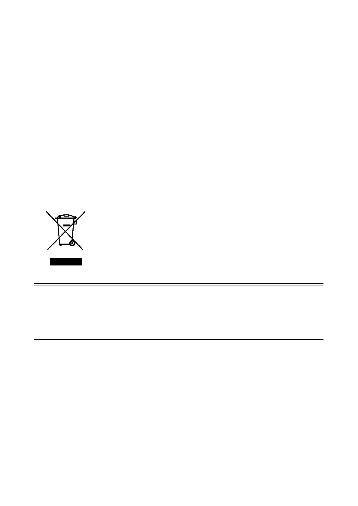
■ About the European WEEE Directive
This instrument and its accessories are subject to the European WEEE Directive.
Follow the applicable regulations of your country or region when discarding this
instrument or its accessories. Follow the EU Battery Directive when discarding the
batteries that you removed from this instrument.
(WEEE stands for Waste Electrical and Electronic Equipment.)
Follow the warnings and precautions that have been listed in this section to use the instrument correctly
and safely. Precautions are also contained in various other sections of this instruction manual. To use the
instrument correctly, be sure to follow those precautions as well.
If you have any questions or comments about this instruction manual, please contact your local LEADER
agent.
IV
Page 8
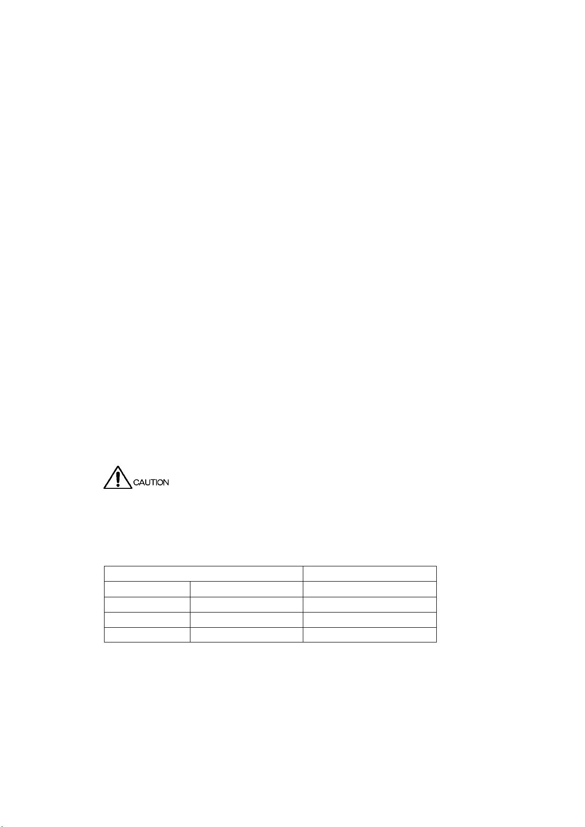
1. INTRODUCTION
Input Connector
Maximum Allowable Voltage
Main unit
EXT REF
±5 V (DC + peak AC)
Main unit
REMOTE
0 to 5 VDC
SER01
SDI INPUT
±2 V (DC + peak AC)
SER02
SDI INPUT
±2 V (DC + peak AC)
1. INTRODUCTION
Thank you for purchasing this LEADER instrument. To use this instrument safely, read this
instruction manual thoroughly, and make sure that you know how to use the instrument properly.
If some point about the operation of this instrument is still unclear after you have read this
instruction manual, refer to the contact information on the back cover of the manual to contact
LEADER, or contact your local LEADER agent.
After you have finished reading this manual, keep it in a convenient place so that you can refer to
it when necessary.
1.1 Scope of Warranty
This LEADER instrument has been manufactured under the strictest quality control guidelines.
LEADER shall not be obligated to furnish the following free services during the warranty period.
1. Repair of malfunction or damages resulting from fire, natural calamity, or improper voltage
applied by the user.
2. Repair of a product that has been improperly repaired, adjusted, or modified by personnel
other than a factory-trained LEADER representative.
3. Repair of malfunctions or damages resulting from improper use.
4. Repair of malfunctions caused by devices other than this instrument.
5. Repair of malfunctions or damages without the presentation of a proof of purchase or receipt
bill for the instrument.
This Warranty is valid only in Japan.
1.2 Operating Precautions
1.2.1 Maximum Allowable Input Voltage
The maximum signal voltage that can be applied to the input connectors is indicated below.
Do not apply excessive voltage to the connectors. Doing so may damage the device or lead to
injury.
Table 1-1 Maximum allowable input voltage
1
Page 9

1.2.2 Mechanical Shock
This instrument contains sensitive components, so it may be damaged if it is dropped or
otherwise exposed to a strong shock.
1.2.3 Electrostatic Damage
Electronic components can be damaged by static discharge. Static electricity can build up in
the core wire of a coaxial cable. Before connecting a coaxial cable to an I/O connector of the
instrument, short the core wire of the cable with the external conductor.
1.2.4 Warming Up
To ensure more accurate measurements, turn ON the instrument approximately 30 minutes
before you intend to use it to allow its internal temperature to stabilize.
1.2.5 About Standby Mode
Even if you press the power switch to turn off this instrument, the instrument remains in
standby mode as long as the power cord is connected to the outlet. In standby mode, some of
the internal circuits operate and may generate heat. Unless necessary, keep the power cord
disconnected from the outlet.
1.2.6 Backup
1. INTRODUCTION
This instrument has a last-memory feature. When you turn the power on, the instrument
starts with the panel settings that were in use the last time that it was turned off. If the backup
battery is out of power, the message "The last memory feature is disabled." will appear, and
this last-memory feature will no longer work.
To continually use the last-memory feature, we recommend that you replace the backup
battery with a new one every five years after you purchase the instrument. You cannot replace
the backup battery yourself. For details, contact your nearest LEADER agent.
1.2.7 About the LCD Panel (LV5300/LV5350)
There may be a small number of pixels in the LCD panel that do not light or are always on. Note
that this is not a malfunction.
The LCD panel supports a large number of video signals. SDI input signals are displayed
asynchronously on the LCD. Therefore, images may appear to flicker on the waveform and
picture displays.
In addition, the input SDI signal is temporarily stored in frame memory and is loaded by using
the LCD display synchronization signal—which is not synchronized with the input SDI signal.
Therefore, because frame skip—which skips over frames in the memory—and frame
repeat—which reads the same frames of the memory twice—occur, the image may appear to
flicker.
(An external sync signal can be used to synchronize the LCD to the input signal.)
2
Page 10

1. INTRODUCTION
1.3 About Trademarks and Licenses
The company and product names in this document are trademarks or registered trademarks of
their respective holders.
DynaFont is a registered trademark of DynaComware Taiwan Inc.
This product uses open source software under the GNU General Public License
(http://www.gnu.org/copyleft/gpl.html
If you need the source code covered by the GNU General Public License, CONTACT YOUR LOCAL
LEADER AGENT.
[Notes]
1. Leader does not provide warranty or support for the software covered by the GNU General
Public License.
2. Alteration and distribution of this program shall be performed under your responsibility.
3. The expense of Leader distributing the software to you shall be borne by you.
1.4 Terminology Used in This Manual
).
●SER**
LV5300-SER**, LV5350-SER** and LV7300-SER** are referred to as SER**.
●Single Input Mode
This refers to the mode in which on the INPUT menu, F•7 DISPLAY is set to SINGLE.
It is a mode for measuring a single input signal.
●Simul Mode
This refers to the mode in which on the INPUT menu, F•7 DISPLAY is set to SIMUL.
It is a mode for measuring multiple input signals simultaneously.
●Multi-screen Display
This refers to the mode in which the MULTI key is on.
●Underlining (_)
Underlined options indicate the default values.
3
Page 11
1. INTRODUCTION
Name
Description
Link System
SD
SD-SDI
Single link
HD
HD-SDI
Single link
3G-A
3G-SDI level A
Single link
3G-B-DL
3G-SDI level B dual link mapping
Single link
12G
12G-SDI TYPE 1
Single link
3G
Collective name for 3G links
-
3G-B
Collective name for 3G-B-DL and 3G-B-DS
-
4K
Collective name for 12G
-
●Input Formats and Link Systems
The following names are used for the input formats and link systems.
Multi link may be used as a collective term to refer to dual link and quad link.
Table 1-2 Input formats and link systems
4
Page 12
2. Product Configuration
Function
support
support
2. PRODUCT CONFIGURATION
2.1 Lineup
LV5300 WAVEFORM MONITOR Built-in LCD
LV5350 WAVEFORM MONITOR Built-in LCD
LV7300 RASTERIZER External monitor type
2.2 Hardware Options
This instrument operates as a measuring instrument by installing hardware options.
To replace or add hardware options, contact your local LEADER agent. You cannot install or
SDI INPUT -
uninstall units.
Table 2-1 Hardware options
Model Name
LV5300 LV5350 LV7300
Lineup
Standard
LV7300-SER01 SD, HD, 3G SDI input (*1)
SDI INPUT/EYE
BATTERY ADAPTER V MOUNT LV5300-SER11 LV5350-SER11 - V mount type battery adaptor (*2)
BATTERY ADAPTER QR GOLD LV5300-SER12 LV5350-SER12 - QR gold type battery adaptor (*2)
Standard
- LV7300-SER02 SD, HD, 3G SDI input and eye pattern display (*1)
*1 The LV7300 requires the LV7300-SER01, or LV7300-SER02 to be installed.
The LV7300-SER01 and LV7300-SER02 cannot be installed in the instrument at the same time.
*2 The LV5300-SER11 and LV5300-SER12 cannot be installed in the instrument at the same time.
The LV5350-SER11 and LV5350-SER12 cannot be installed in the instrument at the same time.
5
Page 13
2.3 Software Options
The following software options (sold separately) can be installed in the instrument.
If you want to obtain a software option, provide your local LEADER agent with the instrument’s
MAC address (see the LICENSE tab) and serial number (see the rear panel). We will issue a
license key.
When you receive the license key, install the option. Each instrument requires a unique license
key. You cannot use the same key for multiple instruments.
Table 2-2 Software options
2. Product Configuration
Model Name
AUDIO LV5300-SER20 LV5350-SER20 LV7300-SER20 Audio display function
CLOSED CAPTION LV5300-SER21 LV5350-SER21 LV7300-SER21 Japanese closed caption, EIA-608, 708, TELETEXT
CIE LV5300-SER22 LV5350-SER22 LV7300-SER22 CIE Chromaticity Diagram Display function
HDR LV5300-SER23 LV5350-SER23 LV7300-SER23 HDR measurem ent function
TSG LV5300-SER24 LV5350-SER24 LV7300-SER24 SDI signal generation function (*1)
FOCUS ASSIST LV5300-SER25 LV5350-SER25 LV7300-SER25 Focus assist display function
LAYOUT LV5300-SER26 LV5350-SER26 LV7300-SER26 Customized layout function
TA LLY LV5300-SER27 LV5350-SER27 LV7300-SER27 ID, iris, tally display function
4K LV5300-SER28 LV5350-SER28 LV7300-SER28 4K video signal support function
LV5300 LV5350 LV7300
Lineup
Function
*1 You need the LV5300-SER28 to output 4K patterns on the LV5300-SER24.
You need the LV5350-SER28 to output 4K patterns on the LV5350-SER24.
You need the LV7300-SER28 to output 4K patterns on the LV7300-SER24.
2.4 Items Sold Separately
LV5300, LV5350, LV7300
LV7290 Remote controller
AC adaptor
LV5350
LR2530 Rack Mount Adapters
LR2535 Blank Panels
LV7300
LR2731 Rack Mount Adapters
LR2732 Rack Mount Adapters
6
Page 14

3. SPECIFICATIONS
3.1 General
The LV5300 WAVEFORM MONITOR, LV5350 WAVEFORM MONITOR, and LV7300 RASTERIZER
are integrated media measuring and monitoring devices that support various video signals and
audio signals. A built-in LCD type and a rasterizer type for use with an external monitor are
available, so you can choose the model appropriate for your installation location.
The LV5300, LV5350, and LV7300 integrate waveform display technologies, measurement
technologies, and monitoring technologies that Leader has accumulated over the years to
provide both high functionality and superb operability.
In terms of video signals, these instruments support a variety of SDI signals up to 12G-SDI. The
video signal waveform display, vector display, picture display, and eye pattern display enable
measurements and quality control of various video signals. The status display allows you to view
various error statuses and system stability in the form of event logs and long-term charts.
In terms of audio signals, these instruments support digitally embedded audio signals in SDI.
Level display, Lissajous display, status display, and so on are available.
In addition to the keys and knobs available on conventional models, these instruments can be
controlled through a USB mouse, the touch panel (*1), and on the LV7300, a set of dedicated
keys for frequently used camera adjustment menus.
Moreover, a rich lineup of options is available in addition to these powerful functions and
operability. Through the combination of these options, these instruments can be used in the
measurement, monitoring, and evaluation of video and audio signals in a wide variety of
applications including (1) broadcast station master monitoring applications for the integrated
monitoring of video and audio signals, (2) monitoring applications for monitoring the quality of
transmission signals, (3) studio sub and post production applications for controlling the video
signal levels, and (4) broadcast equipment compliance applications for determining whether
video and audio signals comply with appropriate standards.
*1 The LV7300 requires a touch-panel type external monitor to be connected to the main unit. The touch
panel interface on the external monitor is connected to the LV7300’s USB port. The video interface on
the external monitor is connected to the LV7300s monitor output connector.
LEADER does not guarantee that all touch panel type monitors will work with the LV7300.
3. SPECIFICATIONS
7
Page 15

3.2 Features
●Support for a Variety of SDI Signal Inputs
The abundant video signal input options enable measurement and monitoring of SDI signals.
In terms of audio signals, SDI embedded audio is supported. The supported audio format is
L-PCM.
●Superb Operability
Operability was prioritized in the design of these instruments. You can use the best control
interface according to your liking or situation. In addition to the conventional keys and knobs
on the front panel, you can control the instrument remotely using a USB mouse. Further, the
LV5300 and LV5350 have a 7-inch full-HD touch panel. The LV7300 can be connected to a USB
touch panel interface of a touch-panel monitor. These interfaces allow intuitive control and
configuration through touch operation.
●Compact
While providing high flexibility through various options and high functionality for various
situations, the LV5300 and LV5350 are 3U half-rack size and the LV7300 1U full-rack size.
●4K Video Format (SER28)
3. SPECIFICATIONS
In addition to SD-SDI, HD-SDI, 3G-SDI single link, 12G-SDI single link are supported. These
cover SDI signals from SD video format to HD video format and even 4K video format.
●Transmission Quality Analysis Function
Signal analysis functions have been enhanced based on the SDI signal measurement
technology that Leader has cultivated over the years. Other enhancements have been made to
various transmission error monitoring, external sync phase difference display, lip sync
measurement (SER20), SDI signal frequency deviation measurement function, equivalent
cable length meter function, and the ancillary data analysis function, which has become more
important with the introduction of 4K video signals.
●Video Analysis Functions
Numerous types of displays are available for the various video signals such as the video signal
waveform display, vector display, picture display, 5-bar display, and CIE chromaticity diagram
display (SER22). In addition, quality control (QoE) functions for video signals are available
including freeze error, black error, and gamut error detection functions. Detected errors can be
recorded in event logs.
●Audio Analysis Functions (SER20)
For audio signals, level meter display is possible on audio signals embedded in SDI.
The SER20 AUDIO option allows Lissajous display, Surround display and detection of mute and
clip errors. Detected errors can be recorded in event logs.
●Eye Pattern Display (LV5300/LV7300-SER02/SER28) (*1)
Eye pattern display and jitter display, which are physical layer measurements of SDI signals
from SD-SDI to 12G-SDI, are possible. These physical layer measurements can be performed
using cursors or performed automatically. Measurements can be exported via a network.
8
Page 16

3. SPECIFICATIONS
●Closed Caption Decode Display Function (SER21)
Japanese closed captions, English closed captions, TELETXT, and OP47 embedded in SDI
signals can be decoded and displayed.
●External Sync Signal Input
The phase difference and synchronization states of SDI video signals can be shown graphically
based on an external reference sync signal (black burst, tri-level sync).
●Customizable Layout (SER26)
Video signal waveforms, vector waveforms, picture, and other items of input video signals can
be laid out freely in the sizes of your choice.
●SDI Signal Generation Function (SER24/SER28)
The simple SDI signal generator supports HD-SDI to 12G-SDI. For the pattern, you can select
the HD multiformat color bar, the 4K multiformat color bar, or the flat field pattern, which
allows you to select any level. You can also overlay a moving box or insert embedded audio.
●Screen Capture Feature
A screen capture feature, which captures the entire display as still-image data, is available. Not
only can captured data be displayed on the instrument, but it can also be compared with an
input signal or saved to a USB memory device as bitmap data for viewing on a PC.
●Time Code Display
The timecodes embedded in SDI signals can be displayed. The timecode can also be used as
the timestamp in the event log.
●External Remote Connector
A contact terminal can be used to load presets, switch the input signal, and transmit alarms.
●Ethernet Port
By connecting the Ethernet interface to a PC, you can control the LV5300, LV5350, and LV7300
remotely over TELNET, transfer files over FTP, control the LV5300, LV5350, and LV7300
remotely and detect errors over SNMP, and control the LV5300, LV5350, and LV7300 over
HTTP. You can also connect to the separately-sold LV7290 REMOTE CONTROLLER.
●HDR (SER23)
Level monitoring is possible on HLG and PQ defined in ITU-R BT.2100 as well as
S-Log3-compatible HDR signals. Level control is possible based on the estimated brightness
(nits, cd/m
2
) of a display taking the OOTF into consideration. Video signal waveform display
supports IRE scale as well as HDR scale. On CINEZONE display, the SDR area is displayed in
monochrome, while the HDR area is displayed using colors corresponding to the brightness.
This makes it easy to view the brightness distribution in the HDR area.
●Focus Assist (SER25)
A new focusing algorithm based on nonlinear super-resolution technology has been developed,
allowing highly sensitive focusing even on low-contrast images that were difficult to be focused
in on in the past. You can select the sensitivity according to the image scene.
*1 Only SDI INPUT 1 supports the eye pattern display.
*2 LEADER does not guarantee the operation on all HDMI monitors.
9
Page 17
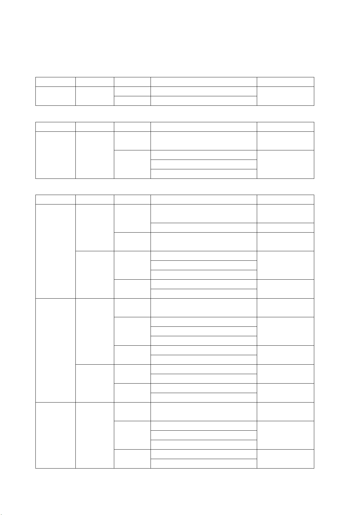
3. SPECIFICATIONS
Color System
Quantization
Image
Field Frequency/Scanning
Compliant Standard
720×487
59.94 /I
720×576
50 /I
Color System
Quantization
Image
Frame (Field) Frequency/Scanning
Compliant Standard
SMPTE ST 296
60/59.94/50 /I
30/29.97/25/24/23.98 /P
30/29.97/25/24/23.98 /PsF
Color System
Quantization
Image
Frame (Field) Frequency/Scanning
Compliant Standard
SMPTE ST 425-1
48/47.95 /P
-
SMPTE ST 2048-2
60/59.94/50 /I
30/29.97/25/24/23.98 /P
30/29.97/25/24/23.98 /PsF
30/29.97/25/24/23.98 /P
SMPTE ST 2048-2
30/29.97/25/24/23.98 /PsF
SMPTE ST 425-1
60/59.94/50 /I
30/29.97/25/24/23.98 /P
30/29.97/25/24/23.98 /PsF
30/29.97/25/24/23.98 /P
SMPTE ST 2048-2
30/29.97/25/24/23.98 /PsF
60/59.94/50 /I
SMPTE ST 425-1
30/29.97/25/24/23.98 /P
30/29.97/25/24/23.98 /P
SMPTE ST 2048-2
30/29.97/25/24/23.98 /PsF
SMPTE ST 425-1
60/59.94/50 /I
30/29.97/25/24/23.98 /P
30/29.97/25/24/23.98 /PsF
30/29.97/25/24/23.98 /P
SMPTE ST 2048-2
30/29.97/25/24/23.98 /PsF
3.3 Specifications
3.3.1 SDI Video Formats and Standards (SER01/SER02/SER24/SER28)
Table 3-1 SD video signal formats and standards
YCBCR 4:2:2 10 bit
SMPTE ST 259
Table 3-2 HD video signal formats and standards
YCBCR 4:2:2 10 bit 1280×720 60/59.94/50/30/29.97/25/24/23.98 /P SMPTE ST 292-1
1920×1080
SMPTE ST 274
SMPTE ST 292-1
Table 3-3 3G-A video signal formats and standards
YCBCR 4:2:2 10 bit 1920×1080 60/59.94/50 /P SMPTE ST 274
2048×1080 60/59.94/50/48/47.95 /P SMPTE ST 425-1
12 bit 1920×1080
SMPTE ST 274
SMPTE ST 425-1
2048×1080
YCBCR 4:4:4 10 bit 1280×720 60/59.94/50/30/29.97/25/24/23.98 /P SMPTE ST 296
1920×1080
2048×1080
12 bit 1920×1080
2048×1080
RGB 4:4:4 10 bit 1280×720 60/59.94/50/30/29.97/25/24/23.98 /P SMPTE ST 296
1920×1080
2048×1080
SMPTE ST 425-1
SMPTE ST 274
SMPTE ST 425-1
SMPTE ST 425-1
SMPTE ST 274
SMPTE ST 425-1
SMPTE ST 274
SMPTE ST 425-1
SMPTE ST 425-1
10
Page 18
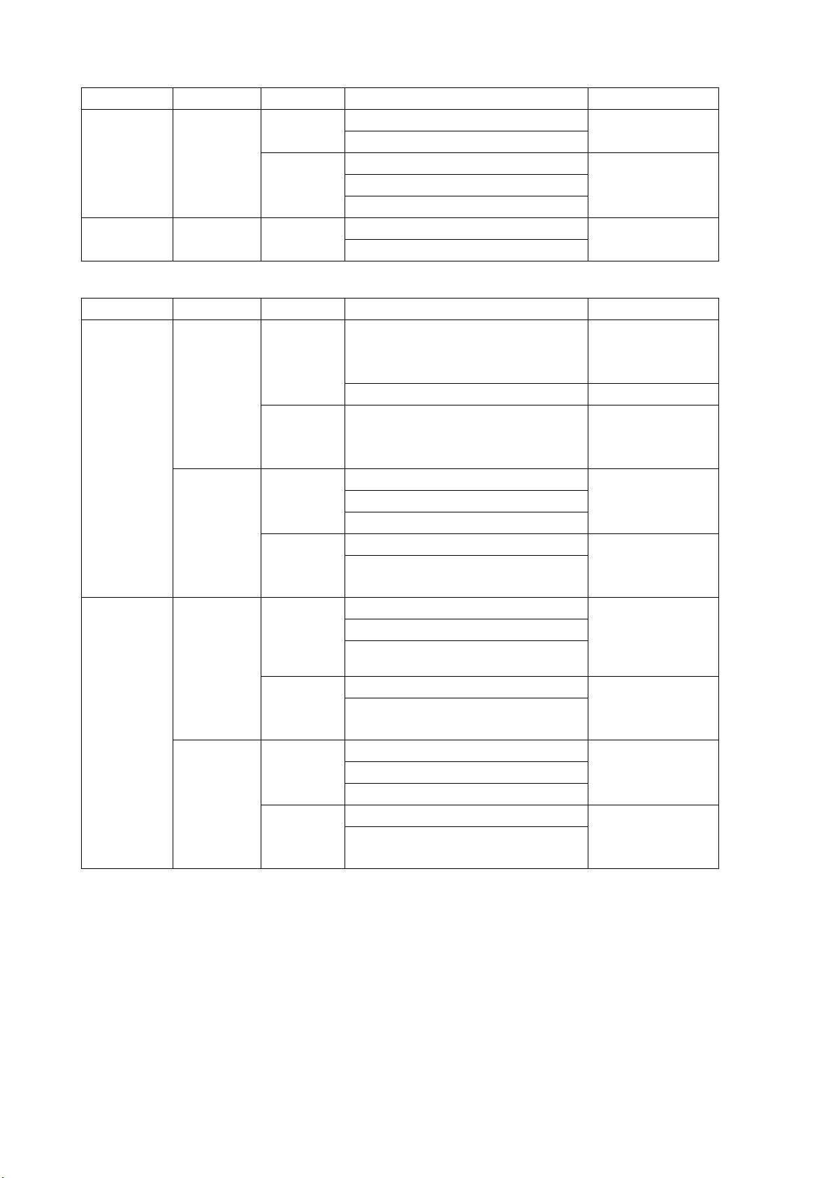
3. SPECIFICATIONS
Color System
Quantization
Image
Frame (Field) Frequency/Scanning
Compliant Standard
60/59.94/50 /I
SMPTE ST 425-1
30/29.97/25/24/23.98 /P
30/29.97/25/24/23.98 /P
30/29.97/25/24/23.98 /PsF
30/25/24 /PsF
30/25/24 /P
SMPTE ST 428
30/25/24 /PsF
Color System
Quantization
Image
Frame (Field) Frequency/Scanning
Compliant Standard
SMPTE ST 425-1
48/47.95 /P
-
SMPTE ST 2048-2
60/59.94/50 /I
SMPTE ST 425-1
30/29.97/25/24/23.98 /P
30/29.97/25/24/23.98 /PsF
30/29.97/25/24/23.98 /P
SMPTE ST 2048-2
60/59.94/50 /I
30/29.97/25/24/23.98 /P
30/29.97/25/24/23.98 /P
SMPTE ST 2048-2
60/59.94/50 /I
SMPTE ST 425-1
30/29.97/25/24/23.98 /P
30/29.97/25/24/23.98 /PsF
30/29.97/25/24/23.98 /P
SMPTE ST 2048-2
12 bit 1920×1080
2048×1080
XYZ 4:4:4 12bit 2048×1080
SMPTE ST 274
SMPTE ST 425-1
SMPTE ST 2048-2
SMPTE ST 425-1
Table 3-4 3G-B-DL Video Signal Formats and Standards
YCBCR 4:2:2 10 bit 1920×1080 60/59.94/50 /P SMPTE ST 274
SMPTE ST 372
2048×1080 60/59.94/50/48/47.95 /P SMPTE ST 372
SMPTE ST 425-1
12 bit 1920×1080
SMPTE ST 274
SMPTE ST 372
2048×1080
YCBCR 4:4:4 10 bit 1920×1080
2048×1080
12 bit 1920×1080
2048×1080
30/29.97/25/24/23.98 /PsF
30/29.97/25/24/23.98 /PsF
30/29.97/25/24/23.98 /PsF
30/29.97/25/24/23.98 /PsF
SMPTE ST 372
SMPTE ST 425-1
SMPTE ST 274
SMPTE ST 372
SMPTE ST 425-1
SMPTE ST 372
SMPTE ST 425-1
SMPTE ST 274
SMPTE ST 372
SMPTE ST 372
SMPTE ST 425-1
11
Page 19
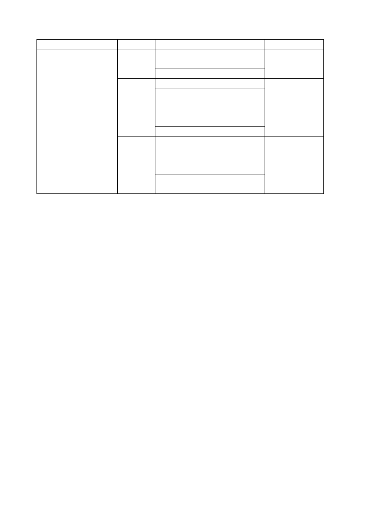
3. SPECIFICATIONS
Color System
Quantization
Image
Frame (Field) Frequency/Scanning
Compliant Standard
60/59.94/50 /I
SMPTE ST 425-1
30/29.97/25/24/23.98 /P
30/29.97/25/24/23.98 /PsF
30/29.97/25/24/23.98 /P
SMPTE ST 2048-2
60/59.94/50 /I
SMPTE ST 425-1
30/29.97/25/24/23.98 /P
30/29.97/25/24/23.98 /PsF
30/29.97/25/24/23.98 /P
SMPTE ST 2048-2
30/25/24 /P
SMPTE ST 428
RGB 4:4:4 10 bit 1920×1080
2048×1080
12 bit 1920×1080
2048×1080
XYZ 4:4:4 12bit 2048×1080
30/29.97/25/24/23.98 /PsF
30/29.97/25/24/23.98 /PsF
30/25/24 /PsF
SMPTE ST 274
SMPTE ST 372
SMPTE ST 372
SMPTE ST 425-1
SMPTE ST 274
SMPTE ST 372
SMPTE ST 372
SMPTE ST 425-1
SMPTE ST 372
SMPTE ST 425-1
12
Page 20
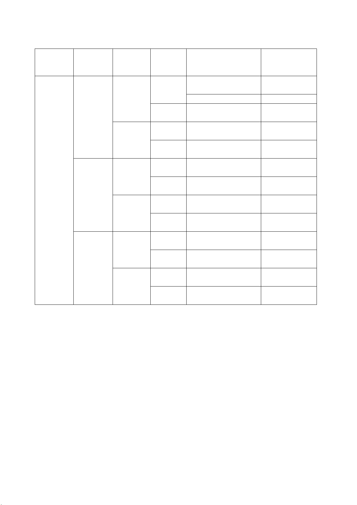
Table 3-5 12G video signal formats and standards
System
SMPTE ST 2082-10
48/47.95/P
-
SMPTE ST 2082-10
SMPTE ST 2082-10
SMPTE ST 2082-10
SMPTE ST 2082-10
SMPTE ST 2082-10
SMPTE ST 2082-10
SMPTE ST 2082-10
SMPTE ST 2082-10
SMPTE ST 2082-10
SMPTE ST 2082-10
SMPTE ST 2082-10
Division
Transmission
3. SPECIFICATIONS
Color System Quantization Image Frame Frequency/Scanning Compliant Standard
2 sample
interleave
YCBCR 4:2:2 10 bit 3840×2160 60/59.94/50 /P SMPTE ST 2036-1
4096×2160 60/59.94/50/48/47.95 /P SMPTE ST 2048-1
12 bit 3840×2160 30/29.97/25/24/23.98 /P SMPTE ST 2036-1
4096×2160 30/29.97/25/24/23.98 /P SMPTE ST 2048-1
YCBCR 4:4:4 10 bit 3840×2160 30/29.97/25/24/23.98 /P SMPTE ST 2036-1
4096×2160 30/29.97/25/24/23.98 /P SMPTE ST 2048-1
12 bit 3840×2160 30/29.97/25/24/23.98 /P SMPTE ST 2036-1
4096×2160 30/29.97/25/24/23.98 /P SMPTE ST 2048-1
RGB 4:4:4 10 bit 3840×2160 30/29.97/25/24/23.98 /P SMPTE ST 2036-1
12 bit 3840×2160 30/29.97/25/24/23.98 /P SMPTE ST 2036-1
* You also need the SER28.
4096×2160 30/29.97/25/24/23.98 /P SMPTE ST 2048-1
4096×2160 30/29.97/25/24/23.98 /P SMPTE ST 2048-1
13
Page 21

3. SPECIFICATIONS
3.3.2 SDI Audio Formats and Standards (SER01/SER02/SER20)
Compliant Standard
12G, 3G, HD, HD(DL) SMPTE ST 299
SD SMPTE ST 272
Sampling Frequency 48 kHz
Quantization 24 bit
Format L-PCM
Clock Generation Generated from the video clock
Synchronization Synchronized to the video signal
SDI Audio Channel Separation
Separates up to two groups (8 channels) from an SDI input.
3.3.3 SDI Input Connector (SER01/SER02/SER28)
SDI Input Connector
Connector Type BNC
Number of Input Connectors
2 (SDI INPUT 1 / 2)
Input Impedance 75Ω
Input Return Loss
5 MHz to 1.485 GHz -15 dB or more
1.485 to 2.970 GHz -10 dB or more
2.970 to 5.940 GHz -7 dB or more (SDI INPUT 1)
5.940 to 11.880 GHz -4 dB or more (SDI INPUT 1)
Maximum Input Voltage ±2 V (DC + peak AC)
Eye Pattern Display Eye pattern display is possible only on SDI INPUT 1.
14
Page 22

3. SPECIFICATIONS
3.3.4 SDI Output Connector (SER01/SER02/SER24/SER28)
SDI Output Connector
Connector Type BNC
Number of Output Connectors
2 (SDI OUTPUT 1 / 2)
Output Impedance 75Ω
Output Return Loss
5 MHz to 1.485 GHz -15 dB or more
1.485 to 2.970 GHz -10 dB or more
2.970 to 5.940 GHz -7 dB or more
5.940 to 11.880 GHz -4 dB or more
Output Voltage 800 mVp-p ± 10 % (into 75 Ω)
Output Signal Reclocked signal of SDI input (*1), TSG output, SDI monitor
output (LV5300/LV5350)
3.3.5 External Reference Input
Connector Type BNC
Number of Input Connectors 1 pair
Input Impedance 15 kΩ passive loop-through
Input Return Loss ≥ 30 dB for 50 kHz to 30 MHz into 75 Ω
Maximum Input Voltage ±5 V (DC + peak AC)
Input Signal Tri -level sync or NTSC/PAL black burst signal
10 field IDs are supported.
Function Video signal waveform display and phase difference display
based on the phase of an external sync signal
* The display position of the video signal waveform display and the measured phase of the phase
difference display based on the phase of the external sync signal may vary by ±1 clock depending on
the timing when the external sync signal or SDI signal is connected or disconnected or when the
device is restarted.
* Video signal waveform display based on the phase of an external sync signal is not possible for the
following formats.
• 3G’s 720/30P, 720/29.97P, 720/25P, 720/24P, 720/23.98P
• 12G
• Frame frequency 48P, 47.95P
* Phase difference display based on the phase of an external sync signal is not possible for the
following formats.
• 3G’s 720/30P, 720/29.97P, 720/25P, 720/24P, 720/23.98P
• Frame frequency 48P, 47.95P
15
Page 23
3. SPECIFICATIONS
Color System
Quantization
Image
Frame (Field) Frequency/Scanning
Compliant Standard
60/59.94/50 /I
60/59.94/50 /P
3.3.6 Monitor Output Connector (LV7300)
SDI Output Connector
Function Output the displayed screen to an SDI monitor
Output Connector BNC
Number of Output Connectors
1
Output Impedance 75Ω
Output Return Loss
5 MHz to 1.485 GHz 15 dB or more
1.485 to 2.97 GHz 10 dB or more
Output Voltage 800 mVp-p ± 10 % (into 75 Ω)
Output Signal Outputs the LCD screen in HD, 3G-A, or 3G-B-DL.
Output Format
YCBCR 4:2:2 10 bit 1920×1080
Synchronization Synchronized with the LCD refresh rate
SMPTE ST 274
(free run)
16
Page 24

TMDS Output Connector
Function Output the displayed screen to an HDMI monitor (*1)
Output Connector HDMI
Number of Output Connectors
Signal Format Single Link T.M.D.S
DDC Not supported
HOT PLUG Detection Not supported
Output Signal Outputs the LCD screen
Image 1920×1080
Frame Frequency 60P, 59.94P, 50P
Synchronization Synchronized with the LCD refresh rate
Touch Control Touch control possible by connecting the USB touch panel
*1 LEADER does not guarantee the operation on all HDMI monitors.
*2 LEADER does not guarantee that all touch panel type monitors will work with the LV7300.
3.3.7 Headphone Output
3. SPECIFICATIONS
1
(free run)
interface of a touch panel monitor to the LV5300, LV5350 or
LV7300 (*2)
Output Connector
LV5300、LV5350 One 3.5 mm mini jack (stereo)
LV7300 One stereo jack
Output Signal 2 channels from the audio signals that are being displayed on
Sampling Frequency 48 kHz
Volume Adjustment Using the menu
Power Output 100 mW maximum (into 8 Ω load)
3.3.8 Control Connectors
USB Port
Port Type Standard A
Number of Ports 2
Specifications USB 2.0
Compatible Devices USB memory, USB mouse, touch panel monitor
USB Memory Feature Saves capture data, preset data, event log data, and data
USB Mouse Feature Used to control on the screen
Touch panel monitor Touch control of the displayed screen (*1, *2)
the screen
(downmixed Lt and Rt are also possible)
dumps
17
Page 25

Ethernet Port
Compliant Standard IEEE802.3
Supported Protocol TELNET (*3), FTP, SNMP, HTTP, SNMP
Connector Type RJ-45
Type 10Base-T / 100Base-TX / 1000Base-T
Remote Connector
Port Type 15-pin D-sub (female)
Locking Screws Inch screws (No.4-40UNC)
Number of Ports 1
Control Signal LV-TTL level (low active)
Input Voltage Range 0 to 5 V DC
Function Load preset settings, switch input signals, transmit alarm
Alarm Output Outputs alarms signals when a format alarm occurs, when
*1 Pinch out and swipe operations are not supported.
*2 LEADER does not guarantee that all touch panel type monitors will work with the LV7300.
*3 You cannot use TELNET and the LV7290 at the same time.
3.3.9 Front Panel
3. SPECIFICATIONS
All inputs are pulled up to +3.3 V (control is also possible using
+5 V)
signals, and activate tally
various errors occur, when the fan malfunctions, or when the
internal temperature is abnormal
Display (LV5300/LV5350)
LCD Type 7-inch color TFT
Resolution 1920×1080
Refresh Rate 60 Hz, 59.94 Hz, 50 Hz
(free run)
Touch Panel Electrostatic touch panel
Tapping the display shows touch keys
Key LEDs All the keys are dimly back-lit.
The selected key is lit more brightly.
Power Switch Electronic switch (which remembers whether the instrument is
on or off)
Last Memory Backs up the panel settings to memory
Key Lock Lock by holding down the SYS key. Prevents unintentional
operations on the instrument.
18
Page 26

3.3.10 Capturing
Screen Capture
Function Captures the screen
Display Displays only the captured image or overlays the captured
Media Internal memory (RAM) and USB memory
Data Output Saved to bitmap format to a USB memory device or to a file
Data Input Data saved to a USB memory device can be loaded and
3. SPECIFICATIONS
image over the input signal
You can only save one screen capture to the internal memory.
format that the instrument can load (BSG).
displayed on the instrument.
19
Page 27
3.3.11 TSG (SER24/SER28)
Color System
Quantization
Image
Frame (Field) Frequency/Scanning
Compliant Standard
60/59.94/50 /P
SMPTE ST 296
30/29.97/25/24/23.98 /P
60/59.94/50 /I
30/29.97/25/24/23.98 /P
30/29.97/25/24/23.98 /PsF
Color System
Quantization
Image
Frame (Field) Frequency/Scanning
Compliant Standard
SMPTE ST 425-1
48/47.95 /P
-
SMPTE ST 2048-2
60/59.94/50 /I
30/29.97/25/24/23.98 /P
30/29.97/25/24/23.98 /PsF
30/29.97/25/24/23.98 /P
SMPTE ST 2048-2
30/29.97/25/24/23.98 /PsF
60/59.94/50 /I
30/29.97/25/24/23.98 /P
30/29.97/25/24/23.98 /PsF
30/29.97/25/24/23.98 /P
SMPTE ST 2048-2
30/29.97/25/24/23.98 /PsF
System
SMPTE ST 2082-10
48/47.95/P
-
SMPTE ST 2082-10
SMPTE ST 2082-10
SMPTE ST 2082-10
SMPTE ST 2082-10
SMPTE ST 2082-10
Table 3-6 HD video signal formats and standards
3. SPECIFICATIONS
YCBCR 4:2:2 10 bit 1280x720
1920×1080
SMPTE ST 292-1
SMPTE ST 274
SMPTE ST 292-1
Table 3-7 3G-A, 3G-B-DL video signal formats and standards
YCBCR 4:2:2 10 bit 1920×1080 60/59.94/50/48/47.95 /P SMPTE ST 274
2048×1080 60/59.94/50/48/47.95 /P SMPTE ST 425-1
YCBCR 4:4:4 10 bit 1920×1080
2048×1080
RGB 4:4:4 10 bit 1920×1080
SMPTE ST 274
SMPTE ST 425-1
SMPTE ST 425-1
SMPTE ST 274
SMPTE ST 425-1
Division
Transmission
2 sample
interleave
2048×1080
SMPTE ST 425-1
Table 3-8 12G video signal formats and standards
Color System Quantization Image Frame Frequency/Scanning Compliant Standard
YCBCR 4:2:2 10 bit 3840×2160 60/59.94/50 /P SMPTE ST 2036-1
4096×2160 60/59.94/50/48/47.95 /P SMPTE ST 2048-1
YCBCR 4:4:4 10 bit 3840×2160 30/29.97/25/24/23.98 /P SMPTE ST 2036-1
4096×2160 30/29.97/25/24/23.98 /P SMPTE ST 2048-1
RGB 4:4:4 10 bit 3840×2160 30/29.97/25/24/23.98 /P SMPTE ST 2036-1
4096×2160 30/29.97/25/24/23.98 /P SMPTE ST 2048-1
* You also need the SER28.
20
Page 28

Output Pattern 100% color bar, 75% color bar, HD multiformat color bar, 4K
Scrolling (*1) ON / OFF
Direction Eight directions (up, down, left, right, and their combinations)
Speed Range and Unit Per frame (field)
Moving Box (*1) ON / OFF
Colors WHITE / YELLOW / CYAN / GREEN / MAGENTA / RED / BLUE /
Speed 1 to 3
Embedded Audio
Number of Embedded Channels
Embedding On/Off On/off at the audio group level
Audio Level -20d BFS, -18 dBFS, 0 dBFS, Mute
*1 Either scrolling, or moving box can be turned on.
*2 For 2048×1080 3G-B-DL format only 8 channels are embedded.
3.3.12 Presets
3. SPECIFICATIONS
multiformat color bar, color raster, gamma, cross hatch, 10
step, limit lamp, check field, lip sync pattern (SER20)
4 to 124 dots, in 4 dot steps
BLACK
16 channels max. (*2)
Preset Saves panel settings (with a few exceptions)
Number of Presets 60
Preset Loading Method Front panel or remote connector (*1)
Copying All preset data can be copied from the instrument to a USB
*1 The number of presets loaded from the remote connector can be 8 or 60.
3.3.13 Display
Number of simultaneously displayed SDI input signals
SD, HD, 3G-A, 3G-B-DL 2
12G (SER28) 1
Display Mode
Single display Displays a single input signal
Simul Display Displays two input signals simultaneously
Alarm Indications
System Alarm Indication Displays an alarm when the fan malfunctions or when the
Error Indication Displays an error when an receive signal error occurs
memory device or from a USB memory device to the
instrument.
internal temperature is abnormal
21
Page 29

3. SPECIFICATIONS
Display Layout
Multi Display Control the WFM/PIC and other display functions in multiple
areas from a single screen
Customized Layout (SER26)
Function Freely arrange the windows shown with the WFM, VECT, PIC,
AUDIO, STATUS, and EYE (LV5300/LV7300-SER02) keys (one
of each), and a window consisting of six displays shown with
MULTI
Display Format Displays up to single link input signals in tiled, mixed, V aligned,
or H aligned mode.
Normal Mode Each display area is divided evenly.
Tiled Display The windows are divided into two quadrants.
Mixed Display The windows are cascaded.
V Aligned Display The windows are arranged top to bottom.
H Aligned Display The windows are arranged side by side.
Tile Mode The display contents arranged in the display are shown in two
quadrants per screen.
V Aligned Mode The display contents arranged in the display are shown in two
vertical divided windows per screen.
H Aligned Mode The display contents arranged in the display are shown in two
horizontally divided windows per screen.
Enhanced Layout (SER26)
Function When multiple channels of single link are displayed, the
selected channel is automatically shown in a specific area.
You can make the specific area larger than the other areas to
show the selected channel enlarged.
Time Display
Displayed Contents Current time, time code
Current Time Display The time based on the internal clock
Time Code Display LTC, VITC, D-VITC (SD only)
Compliant Standard
LTC, VITC SMPTE ST 12-2
D-VITC SMPTE ST 266
Tally Display
Remote Connector Turn on and off the tally display by controlling through the
remote connector
Camera ID Display
Instrument Setting Shows the camera ID set with the instrument’s menu
Iris Display Shows the camera ID set with the instrument’s menu
22
Page 30

3.3.14 Video Signal Waveform Display
Waveform Control
Display Mode
Overlay Overlays component signals
Parade Displays component signals side by side
Blanking Interval H and V blanking periods can be masked.
RGB Conversion Converts a YC
result
Channel Assignment GBR or RGB order
Pseudo-Composite Display Artificially converts component signals into composite signals
and displays the result
Line Select Displays the selected line
Sweep Modes H / V
Color 7 colors to choose from
Vertical Axis
Gain ×1 / ×5 / ×10
Variable Gain
Gain x1 ×0.2 to ×2.0
Gain x5 ×1.0 to ×10.0
Gain x10 ×2.0 to ×10.0
Amplitude Accuracy ±0.5% (single default display)
3G (1080/60P, 1080/59.94P, 1080/50P)
Y Signal ±0.5 % (1 to 60 MHz)
C
Signal ±0.5 % (0.5 to 30 MHz)
BCR
Low-Pass Attenuation ≥ 20 dB (at 40 MHz)
3G, HD (1080/60P, 1080/59.94P, 1080/50P)
Y Signal ±0.5 % (1 to 30 MHz)
C
Signal ±0.5 % (0.5 to 15 MHz)
BCR
Low-Pass Attenuation ≥ 20 dB (at 20 MHz)
SD
Y Signal ±0.5 % (1 to 5.75 MHz)
C
Signal ±0.5 % (0.5 to 2.75 MHz)
BCR
Low-Pass Attenuation ≥ 20 dB (at 3.8 MHz)
Horizontal Axis
Line Display
Display Format Overlay (1H, 2H)
Parade (1H, 2H, 3H)
Magnification ×1 / ×10 / ×20 / ACTIVE / BLANK
Field Display
Display Format Overlay (1V, 2V) (*1)
Parade (1V, 2V, 3V)
Magnification ×1 / ×20 / ×40
Time Accuracy ±0.5% (single default display)
3. SPECIFICATIONS
signal into an RGB signal and displays the
BCR
23
Page 31

3. SPECIFICATIONS
Cursor Measurement
Composition
Horizontal Cursors 2 (REF and DELTA)
Vertical Cursors 2 (REF and DELTA)
Simultaneous Display Displays the horizontal cursors and vertical cursors
simultaneously
Amplitude Measurement mV / % / R% / DEC / HEX
Time Measurement Second display
Frequency Display Computes and displays the frequency with the length of one
period set to the time between two cursors
Cursor Value Display Displays measured values at the cursors
Scale
Type %, V, decimal, hexadecimal
Display Colors 7 colors to choose from
HDR Scale (SER23) Adds an HDR scale to each scale for HDR
*1 2V display is not possible when the input signal is progressive.
24
Page 32

3.3.15 Vector Display
Display Colors 7 colors to choose from
Blanking Interval H and V blanking periods can be masked (according to the
Pseudo-Composite Display Artificially converts component signals into composite signals
Line Select Displays the selected line
Gain ×1 / ×5 / IQ-MAG
Variable Gain
Gain x1 ×0.2 to ×2.0
Gain x5 ×1.0 to ×10.0
Gain IQ-MAG
Not SD, component display
SD, component display
Not SD, pseudo-composite display
SD, pseudo-composite display
Amplitude Accuracy ±0.5 %
Scale
Type AUTO / ITU-R BT.601 / ITU-R BT.709 / DCI / ITU-R BT.2020
Color Bar Saturation 75% / 100%
IQ Axis Show or hide
Display Colors 7 colors to choose from
Vector Marker Display Displays a marker and numeric value at the specified location
Number of Markers 1
Numeric Display Displays the marker position numerically
Cb Displays the C
Cr Displays the C
deg Displays the hue in degrees.
d Displays the distance from the center as a percentage
Histogram Display Displays the Y, R, G, and B histograms
SDI Signal 5-Bar Display
Function Converts an SDI signal into Y, R, G, B, and composite values,
Channel Assignment RGB / GBR
Scale % / mV / HEX / DEC
Error Level Based on the gamut error, composite gamut error, and
Line Select Displays the selected line
Low-Pass Filter The same as for gamut errors
3. SPECIFICATIONS
video signal waveform display settings).
and displays the result
0.620 to 6.240
0.580 to 5.840
0.570 to 5.700
0.520 to 5.260
on the vector display
position as a percentage
B
position as a percentage
R
and then displays the five peak levels.
luminance error thresholds
25
Page 33

3.3.16 Picture Screen
Quantization 8 bit (internal signal processing is performed with signed 12 bit
Level Mapping Maps the black level to 0 (8bit), SDI code value (when receiving
Display Sizes Reduced, actual size, ×2, full frame
Quality Adjustment and Color Selection
Frame Rate Converts the frame rate based on the LCD frame rate (60P,
Aspect Marker Display
3G (17:9 aspect ratio) 16:9 / 14:9 / 13:9 / 4:3 / 2.39:1
3G (16:9 aspect ratio), HD, HD(DL)
SD 16:9 / 14:9 / 13:9 / AFD(*1)
Aspect Marker Format Line, shadow (99 levels), or black
Safety Marker Size ARIB TR-B4, SMPTE RP-218, or user-defined
AFD Display(*1) Displays abbreviations for SMPTE ST 2016-1-2007 standard
Line Select Marks the selected line
Error Indication Displays markers in the gamut error and level error areas
*1 AFD Supports only SD or HD.
3.3.17 Superimpose Display (SER21)
3. SPECIFICATIONS
or higher)
10 bit RGB) 1024 to 255 (8 bit)
Brightness, contrast, RGB gain, RGB bias, chroma gain,
monochrome display (RGB gain, RGB bias, chroma gain not
valid)
59.94P, 50P)
17:9 / 14:9 / 13:9 / 4:3 / 2.39:1 / AFD (*1)
AFD codes
English Closed Caption Display
Displays a simple English closed caption on the picture display.
Compliant Standard
EIA-708 SMPTE ST 334
EIA/CEA-608-B (EIA-708-B)
SMPTE ST 334
EIA/CEA-608-B (EIA/CEA-608-B)
SMPTE ST 334
VBI (EIA/CEA-608-B Line21)
CIA/EIA-608-B
Europe Closed Caption Display
Displays a simple Europe closed caption on the picture display.
Compliant Standard
TELETXT TU-R BT. 653-3 System B / OP47
Simple Japanese Closed Caption Display
Displays a simple Japanese closed caption on the picture
display. (Select HD, SD, analog, or portable closed caption to
display. Select language 1 or 2.)
Compliant Standard ARIB STD-B37 short form data
Supported Video Formats 1080i/59.94 (SMPTE 274M, 292)
26
Page 34

Display Display position control is supported only for HD and SD closed
Characters Only Kanji, roman numerals, katakana, hiragana, additional
Character Sizes Supports only standard, medium, small, and specified size
Logging
Logged Events Clear screen command, text closed caption display event, time
Data Format Tex t
3. SPECIFICATIONS
525i/59.94 (SMPTE 259M)
captions.
characters (ARIB STD-B24), additional kanji (ARIB STD-B24),
and 1-byte DRCS are displayed.
codes
code, TV commercial material check result
27
Page 35

TV Commercial Material Checking
Function Checks whether closed caption displays are present during the
Check Period The material start time and end time can be specified using
Log Display Color
Closed Caption during Prohibited Time
Closed Caption Not during Prohibited Time
Check Result Display Displays OK or NG when measurements are complete
3.3.18 CINELITE Display
Function Video levels are displayed numerically.
f Stop Display Displays f Stop values relative to a reference point
Fundamental Gamma ITU-R BT.709 / hybrid log gamma (HLG)(SER23) / PQ (SER23)
User Correction Table 3 types (data acquired with a real device)
% Display (SDR) Displays the luminance level or RGB level as a percentage with
Gradation Display Displays the luminance or RGB value with the SDI code value
CV Display Decimal, hexadecimal
HDR Display (SER23)
HLG
System Gamma OFF
Narrow range Displays the relative HLG luminance with the SDI code value 64
Full range Displays the relative HLG luminance with the SDI code value 4
System Gamma ON
Narrow range Displays the relative HLG luminance with the SDI code value 64
Full range Displays the relative HLG luminance with the SDI code value 4
PQ Converts the luminance level to the display’s cd/m
Narrow range Displays with the SDI code value 64 assumed to 0cd/m
Full range Displays with the SDI code value 0 assumed to 0cd/m
3. SPECIFICATIONS
closed caption prohibited time
timecodes.
Red
Green
Set in reference to an object with an 18% reflectance
f Stop gamma correction (not supported on the SER23)
/ S-Log3 (SER23)
the SDI code value 64 assumed to be 0% and the SDI code
value 940 assumed to be 100%
64 assumed to be 0 and the SDI code value 940 assumed to be
255
Displays the SDI signal code value as YCBCR or RGB according
to the input signal
(only for measurement size 1×1)
assumed to 0% and 940 assumed to be 1200% or 100%
assumed to 0% and 1023 assumed to be 1200% or 100%
assumed to 0cd/m
assumed to 0cd/m
2
and 940 assumed to be 1000cd/m2
2
and 1023 assumed to be 1000cd/m2
2
and
displays the result
2
and
940 assumed to be 10000cd/m
2
2
and
28
Page 36

3. SPECIFICATIONS
2
1023 assumed to be 10000cd/m
S-Log3 Converts the reflectance to IRE with SDI code value 95
assumed to be 0% and 589 assumed to be 100% and displays
it as a percentage
Measured Points 3
Measurement Sizes 1 × 1 pixel, 3 × 3 pixels, and 9 × 9 pixels
29
Page 37

3.3.19 CINELITE Advanced Display
Function Synchronizes the markers on the waveform display, vector
Waveform Display Link Markers
Number of Link Markers Up to 16 (for YRGB, YGBR display) (including the 4 reference
Vector Link Markers Synchronizes the markers on the vector display to the points
Number of Link Markers Up to 4 (including the 1 reference point)
Vector Numeric Display Displays numerically the active marker position
Cb Displays the CB position as a percentage
Cr Displays the CR position as a percentage
deg Displays the hue as an angle (°).
d Displays the distance from the center as a percentage
CIE Chromaticity Diagram Display Link Markers (SER22)
Number of Link Markers Up to 4 (including the 1 reference point)
3.3.20 CINEZONE Display
3. SPECIFICATIONS
display, and chromaticity diagram display to the points selected
with CINELITE
Synchronizes the markers on the waveform display to the
points selected with CINELITE
points)
selected with CINELITE
Synchronizes the markers on the CIE chromaticity diagram
display to the points selected with CINELITE
CINEZONE Display (SDR)
Function Adds colors to the display in accordance with luminance levels
Display Colors Linear (1024 colors), step (12 colors)
Upper Limit -6.3 to 109.4 % (values equal to or greater than the upper limit
are displayed in white)
Lower Limit -7.3 to 108.4 % (values less than the lower limit are displayed
CINEZONE display (HDR) (SER23)
Function Adds colors to the display in accordance with luminance levels
HDR Area Setting Displays color according to the brightness
SDR Area Setting Monochrome display
Upper Limit Displays magenta for values exceeding the limit
Lower Limit Displays black for values less than the limit
in black)
Ref.LEVEL to 100% (code values 64 to 940 assumed to be
100%, or code values 0 to 1023 assumed to be 100%)
0% to Ref.LEVEL% (code values 64 to 940 assumed to be
100%, or code values 0 to 1023 assumed to be 100%)
30
Page 38

3. SPECIFICATIONS
3.3.21 Focus Assist (SER25)
Detection Sensitivity LOW / MIDDLE / HIGH
Highlight Display Color WHITE / GREEN / BLUE / RED
Picture Luminance Level OFF / EMBOSS / 25% / 50% / 75% / 100%
3.3.22 CIE Chromaticity Diagram Display (SER22)
Display Standard CIE1931 (xy display), CIE1976 (u'v’ display)
Display Type Chromaticity diagram display, color temperature display
Display Mode
Chromaticity Diagram Display
Luminance display, color display
Color Temperature Display Luminance display
Colorimetry ITU-R BT.601(525) / ITU-R BT.601(625) / BT.709 / DCI / ITU-R
BT.2020
Clipping
ON Clips negative values of the input signal to zero
OFF Displays negative values of the input signal according to ITU-R
BT.1361
Smoothing Displays by averaging data every two pixels
Accuracy ±0.005 (relative to the measurement coordinate value)
Chromaticity Diagram Display Scale
Triangle Select two from ITU-R BT.601 (525), ITU-R BT.601 (625),
ITU-R BT.709, DCI, and ITU-R BT.2020
User-defined Triangle Set a single user-defined triangle
Background Color sample, white background, black background
Sub scale Color temperature curve, grid (0.1 steps), white point (D65),
triangle name (each can be turned on or off)
Cursor Displays the cursor position in coordinates
Gamma ITU-R BT.709, user (1.5 to 3.0), HLG (SER23), PQ (SER23),
S-Log3 (SER23)
31
Page 39

3.3.23 HDR Display (SER23)
Compliant Standard ITU-R BT.2100 (HLG: Hybrid Log Gamma,
Supported Formats All formats except SD-SDI
Function
Video Waveform Display Scale, cursor
Vector Display Histogram
Picture Screen
HDR CINEZONE
HDR CINELITE
MAXCLL, MAXFALL (CEA861 compliant)
STA RT MAXCLL, MAXFALL computation start
STOP MAXCLL, MAXFALL computation stop
3. SPECIFICATIONS
FullRange/NarrowRange),
ITU-R BT.2100 (PQ: Perceptual Quantization,
FullRange/NarrowRange)
S-Log3
32
Page 40

3.3.24 Audio Display
Input Signal SDI embedded audio
Format L-PCM
Sampling Frequency 48 kHz
Quantization 24 bit
SDI Embedded Audio
Compliant Standard
3G, HD, HD(DL) SMPTE ST 299
SD SMPTE ST 272
Clock Generation Generated from the video clock
Synchronization Must be synchronized to the video clock.
Channel Separation Separates up to two groups (8 channels) from an SDI input.
Maximum Number of Display Channels
Display Types Level meter, Lissajous (SER20), correlation meter (SER20),
Level meter (*1)
Displayed Channels 8ch
Dynamic Range SDI-60 dBFS, -90 dBFS, reference level±3 dB
Level Accuracy ±0.3 dB
Frequency Response 30 Hz to 20 kHz ± 0.4 dB (4 dBu, 1 kHz reference, TRUE PEAK
Meter Response Model TRUE PEAK / PPM typeⅠ / PPM typeⅡ / VU
Peak Hold Time 0.0 to 5.0 s (in 0.5 s steps), HOLD
Level Setting -40.0 to 0.0 dBFS (standard level, warning level, over level)
Level Numeric Display Displays the levels numerically
Lissajous Display (SER20) (*1)
Displayed Channels 2ch×1
Display Mode X-Y / MATRIX
Correlation Meter Displays the correlation between two channels as a value from
Channel Assignment
SINGLE LISSAJOU L / R
MULTI LISSAJOU L1, R1 to L4, R4
3. SPECIFICATIONS
All SDI signals must be synchronized.
8 (from any SDI input, displayed in groups)
surround (SER20), status (SER20)
(-50 to 0 dBFS, 1 kHz, signal source impedance 40 Ω or less)
response)
20 Hz to 20 kHz + 0.4 dB, -0.6 dB (4 dBu, 1 kHz reference,
TRUE PEAK response)
Numeric display in red when level-over is detected
Displays a blue “M” when mute is detected (ON/OFF selectable.
The disp l a y s chang e s to a blu e ■ wh en the la y o u t s ize is sm a l l.)
Displays “U.L” when audio is not detected
2ch×4
-1 to 1
33
Page 41

3. SPECIFICATIONS
Surround Display (SER20) (*1)
Function Displays a graphical representation of a sound field
Surround Format 5.1ch
Channel Mapping L / R / C / LFE / Ls / Rs / Lt / Rt
Center Channel Format NORMAL / PHANTOM CENTER
Gain ×1 / AUTO
Status Display (SER20) (*1)
Level Audio levels are displayed using numbers (dBFS).
Error Detection Counts the number of errors that occur for each channel
Level Over Counts the number of times that the level of the input signal
exceeds the set value
Detection Setting -40.0 to 0.0 dBFS
Clipping Counts the number of times that a received signal exceeds the
maximum signal value for the specified number of consecutive
samples
Detection Setting 1 to 100 sample
Mute Counts the number of times that the length of a received mute
signal exceeds the specified period
Detection Setting 1 to 5000 ms
Parity Error Counts the number of times that the input signal's parity bit
and the parity bit recalculated by the instrument differ
Validity Error Counts the number of times that the input signal's validity bit is
1
CRC Error Counts the number of times that the CRC of the channel status
bits and the calculated CRC are different
Code Violation Counts the number of times that the state of the input signal's
biphase modulation is abnormal
Elapsed Time Displays the amount of time that has elapsed since the
instrument was reset
Channel Status Bits Dump display, text display
User Data Bits Dump Display
Lip Sync Display (SER20) Displays the phase difference between the video and audio
Lip Sync Measurement
Function Measures the time difference between the SDI signal and
digital audio signal and displays the results numerically and
graphically
Reference Signal A Leader TSG that supports lip syncing (*2)
Measurement Method Measures the time difference when the luminance level of the
video signal exceeds the specified value and when the audio
level signal exceeds the specified value
Luminance Level Setting 25 to 100%
Audio Signal Level Setting
-30 to 0 dBFS
Supported Audio Signals Embedded audio signal
Measurement Range (Bar Display)
±50 ms / ±100 ms / ±500 ms / ±1.0 s / ±2.5 s
34
Page 42

Measurement Range (Numeric Display)
Measurement Resolution 1 ms
*1 Level meter, Lissajous, Surround, and Status can be displayed simultaneously. For details, see
section 3.3.13, “Display.”
*2 TSG patterns not made by Leader may be supportable by specifying the video signal setting and
audio signal setting.
3. SPECIFICATIONS
±3999 ms
35
Page 43

3.3.25 Status Display
Signal Detection Detects the presence of an SDI signal
Format Display Displays the video signal format
Frequency Deviation Display
Function Displays the sampling frequency deviation
Measurement Range ±100 ppm
Precision ±2 ppm
Equivalent Cable Length Display
Function Displays SDI signal attenuation in terms of cable length
Supported Cables
12G L-5.5CUHD
3G, HD LS-5CFB / 1694A
SD L-5C2V / 8281
Display Range
12G < 10 m, 10 to 80 m, > 80 m
3G < 10 m, 10 to 100 m, > 100 m
HD < 10 m, 10 to 130 m, > 130 m
SD < 50 m, 50 to 200 m, > 200 m
Precision
12G, 3G, HD ±20 m
SD ±30 m
Resolution 10 m
Error Count Display Up to 999999 errors for each error type
Count Period 1 second, 1 field (frame)
Embedded Audio Channel Display
* If the input signal is 3G-B-DL, only stream 1 is supported.
SDI Signal Error Detection
CRC Error Detects 3G and HD signal transmission errors
EDH Error Detects SD signal transmission errors
TRS Position Error Detects TRS embedding position errors
TRS Code Error Detects TRS protection bit errors
Line Number Error Detects errors with the line numbers embedded in 3G and HD
Illegal Code Error Detects data within the range of 000 to 003h and 3FC to 3FFh
3. SPECIFICATIONS
Displays an error if ±10 ppm is exceeded
Displays an error if the specified cable length is exceeded
Displays the embedded audio channel numbers
signals
in locations other than TRS and ADF
36
Page 44
3. SPECIFICATIONS
Low-Pass Filter
HD/SD: 1 MHz
HD: 2.8 MHz SD: 1 MHz
SD 720×487
Approx. 1 MHz (EBU R103-2000)
Approx. 1 MHz
SD 720×576
Approx. 1 MHz (EBU R103-2000)
Approx. 1 MHz
HD 1280×720
Approx. 1 MHz
Approx. 2.8 MHz
HD 1920×1080 (f rame ra te ≤ 30 Hz)
Approx. 1 MHz (IEEE STD 205)
Approx. 2.8 MHz
HD 1920×1080 (frame rate > 30 Hz)
Approx. 2 MHz
Approx. 5.5 MHz
HD 2048×1080 (frame rate ≤ 30 Hz)
Approx. 1 MHz (IEEE STD 205)
Approx. 2.8 MHz
HD 2048×1080 (frame rate > 30 Hz)
Approx. 2 MHz
Approx. 5.5 MHz
4K 3840×2160 (frame rate ≤ 30 Hz)
Approx. 4 MHz
Approx. 11 MHz
4K 3840×2160 (frame rate > 30 Hz)
Approx. 8 MHz
Approx. 22 MHz
4K 4096×2160 (frame rate ≤ 30 Hz)
Approx. 4 MHz
Approx. 11 MHz
4K 4096×2160 (frame rate > 30 Hz)
Approx. 8 MHz
Approx. 22 MHz
Ancillary Data Packet Error Detection
Checksum error Detects ancillary data transmission errors
Parity Error Detects ancillary data header parity errors
Embedded Audio Packet Error Detection (*1)
BCH Error Detects audio packet transmission errors
DBN Error Detects audio packet continuity errors
Parity Error Detects audio packet parity errors
Embedded Position Error Detects the presence of audio in lines where it should not be
embedded
Sample Counter Error Detects asynchronous audio by measuring the number of audio
samples
*1 If the input signal is 3G-B-DL, only stream 1 is supported.
Video Error Detection
Freeze Error Detects freezing of video within the specified time range
Detection Method Video interval checksum
Time Specification 2 to 300 frames
Black Error Detects video blackouts
Black Level Specification 0 to 100%
Area Specification 1 to 100%
Time Specification 1 to 300 frames
Gamut Error Detects gamut errors
Detection Range
Upper limit 90.8 to 109.4%
Lower Limit -7.2 to 6.1%
Low-Pass Filter
Format
Area Specification 0.0 to 5.0%
Time Specification 1 to 60 frames
37
Page 45

Composite Gamut Error Detects level errors that occur when component signals are
Detection Range
Upper limit 90.0 to 135.0%
Lower Limit -40.0 to 20.0%
Low-Pass Filter The same as the gamut error
Area Specification 0.0 to 5.0%
Time Specification 1 to 60 frames
SDI Analysis Features
Event Log Display
Function Records detected errors, events—such as the instrument
Log Capacity Up to 1000 events
Operation Logs all events from start to finish
Data Output Overwrite mode, Stop after 1,000 events
Data Dump Display
Display Format Displays serial data sequence or displays each color component
SD, HD, 3G-A PICTURE, stream 1, stream 2
3G-B-DL PICTURE, link A, link B
12G (SER28) PICTURE, Sub1, Sub2, Sub3, Sub4
Display Format Details
PICTURE Links or streams 1 and 2 are combined and displayed in a
Stream 1/2 Displays each stream in a transmission structure
Link A, B, 1, 2, 3, 4 Displays the selected link
Line Select Displays the selected line
Sample Select Displays from the selected sample
Jump Feature Jumps to an EAV or SAV
Data Output Text output to USB memory
3. SPECIFICATIONS
converted to composite signals
switching between input signals, and timestamps.
separately
picture structure.
38
Page 46

Phase Difference Display
Function Displays the phase difference between a reference signal and
Reference Signal
SD, HD, 3G-A, 3G-B-DL
12G (SER28) External sync signal
Display Range
Vertical 1 frame
Horizontal ±1 line
* If the reference signal is set to an external sync signal, the measured phase may vary by ±1
clock depending on the timing when the external sync signal or SDI signal is connected or
disconnected or when the power is turned on and off.
SDI Ancillary Data List Display
List Display Details Presence or absence of each ancillary data type, embedded line
Dump Display The selected ancillary data is displayed in hexadecimal or
EDH Display (Only for SD)
Compliant Standard SMPTE RP 165
Displayed Contents Analyzes and displays EDH packets and displays received CRC
Display Format Text, hexadecimal, binary
Payload ID Display
Compliant Standard SMPTE ST 352
Displayed Contents Analyzes and displays payload information
Display Format Text and binary
Displaying Audio Control Packets
Compliant Standard SMPTE ST 299-1, SMPTE ST 272
Displayed Contents Displays audio control packet analysis
Display Format Text, hexadecimal, binary
Display Format 1 / 2 / 3 / 4
Japanese Closed Caption Display(*1)
Compliant Standard ARIB STD-B37
Displayed Contents Analysis display of closed caption signals
Display Format Text, hexadecimal, binary
3. SPECIFICATIONS
an SDI signal numerically and graphically
external sync signal, Ach
For 3G-B-DL 47.95P to 60P, ±1 frame measurement possible
number, and number of packets per frame
binary.
errors
39
Page 47

3. SPECIFICATIONS
English Closed Caption Display(*1)
CDP Packet Display Details
CDP packet header information
Presence or absence of timecode packet,
Presence or absence of closed caption packet and validity of
this packet,
Presence or absence of closed caption service packet and
validity of this packet,
Presence or absence of the FUTURE data packet
Time Code When time code packets are present
Closed Caption Data When valid closed caption packets are present
Presence or absence of CC1 to 4, TEXT1 to 4, XDS packets
XDS Packet Display Details
Contents adviser information
Copy management information
Display content of ProgramDescription packet
Stuffing Descriptor
AC3 Audio Descriptor
Caption Service Descriptor
Content Advisory Descriptor
Extended Channel Name Descriptor
Service Location Descriptor
Time-Shifted Service Descriptor
Component Name Descriptor
DCC Arriving Request Descriptor
DCC Arriving Request Descriptor
Redistribution Control Descriptor
Inter-Stationary Control Signal (NET-Q) Display (*1)
ARIB STD-B39
Analysis display of inter-stationary control signals
Text, hexadecimal, binary
Q signal logging
Analysis display of the format ID
Outputs Q signal logs in CSV format through a USB memory
device
Data Broadcast Trigger Signal Display(*1)
ARIB STD-B35
Text, hexadecimal, binary
V-ANC User Data Display(*1)
ARIB TR-B23
Hexadecimal, binary
AFD Packet Display SMPTE ST 2016-3
Text, hexadecimal, binary
40
Page 48

3. SPECIFICATIONS
User-Defined ANC Packet Display
DID / SDID
Y / C
Hexadecimal, binary
*1 This is not supported when the input signal is 3G or 12G (SER28).
3.3.26 Eye Pattern (LV5300/LV7300-SER02)
SDI Input Connector SDI INPUT 1
Display Displays the input SDI waveform before equalizing
Number of Displays
1-Screen Display Displays the eye pattern of the selected filter in a single screen
2-Screen Display Displays the timing filter and eye pattern of the selected filter in
two screens
Waveform Display Color 7 colors to choose from
Scale Display Color 7 colors to choose from
Method Equivalent time sampling
Amplitude Accuracy 800 mV ± 5 % (for 800 mV input)
Time Axis
2 UI Display
12G (SER28) 12.5 ps/div
3G 50 ps /div
HD 100 ps/div
SD 550 ps/div
4 UI Display
12G (SER28) 25 ps/div
3G 100 ps /div
HD 200 ps/div
SD 1100 ps/div
16 UI Display
12G (SER28) 100 ps/div
3G 400 ps /div
HD 800 ps/div
SD 4400 ps/div
Time Axis Accuracy ±3 %
Jitter Filter
10Hz HPF 10Hz
100Hz HPF 100Hz
1 kHz HPF 1 kHz
100 kHz HPF 100 kHz
TIMING HPF 10Hz
ALIGNMENT
12G (SER28) HPF 100 kHz
3G, HD HPF 100 kHz
SD HPF 1 kHz
Cursor Measurement Amplitude measurement using Y cursors
Time measurement using X cursors
41
Page 49

3. SPECIFICATIONS
Rise time and fall time measurement using the TrTf cursor
Automatic Measurement Items
Eye pattern's amplitude
Rise time (the time for the signal to rise from 20 to 80 % of its
amplitude)
Fall time (the time for the signal to fall from 80 to 20 % of its
amplitude)
Timing jitter
Jitter
Rising edge overshoot
Falling edge overshoot
42
Page 50

3. SPECIFICATIONS
3.3.27 Jitter Display (LV5300/LV7300-SER02)
SDI Input Connector SDI INPUT 1
Display Displays the jitter component of an SDI signal
Number of Displays
1-Screen Display Displays the jitter waveform of the selected filter in a single
screen
2-Screen Display Displays the timing jitter and the jitter waveform of the
selected filter in two screens
Waveform Display Color 7 colors to choose from
Scale Display Color 7 colors to choose from
Method Phase detection method
Gain ×16 / ×8 / ×4 / ×2 / ×1
Measurement Range
12G (SER28)
×16 0.00 to 1.20 UI
×4 1.20 to 4.80 UI
×2 4.80 to 9.60 UI
×1 9.60 to 19.20 UI
3G, HD, SD
×8 0.00 to 1.20 UI
×2 1.20 to 4.80 UI
×1 4.80 to 9.60 UI
Time Axis 1H / 2H / 1V / 2V (*1)
Time Axis Accuracy ±3 %
Jitter Filter
10Hz HPF 10Hz
100Hz HPF 100Hz
1 kHz HPF 1 kHz
100 kHz HPF 100 kHz
TIMING HPF 10Hz
ALIGNMENT
12G (SER28) HPF 100 kHz
3G, HD HPF 100 kHz
SD HPF 1 kHz
Cursor Measurement Jitter value measurement through the use of cursors
Automatic Measurement Display Feature
Displays the jitter value in seconds (sec) and unit intervals (UI)
Automatic Measurement Items
Timing jitter, alignment jitter, jitter
Accuracy Input jitter frequency: 1 kHz. Filter setting: 10 Hz, within
measurement range
0 UI < automatic measured value ≤ 1 UI
±10 % + 0.07 UI
1 UI < automatic measured value ≤ 7 UI
±10 %
*1 2V display is not possible when the input signal is progressive.
43
Page 51

3.3.28 Tally Display
Number of Displays 3 (TALLY-1, TALLY-2, TALLY-EXT) (*1)
Display Colors 7 colors to choose from
Control Method Remote connector
*1 The number of displays per channel. Arranged using the customized layout feature or the enhanced
layout feature.
3.3.29 Camera ID Display
Number of Displays 2 (LABEL-1, LABEL-2) (*1)
Iris Display 1 (IRIS) (*1)
Control Method Instrument
*1 The number of displays per channel. Arranged using the customized layout feature or the enhanced
layout feature.
3. SPECIFICATIONS
44
Page 52

3.3.30 General Specifications
Environmental Conditions
Operating Temperature 0 to 40 °C
Operating Humidity Range 85 %RH or less (no condensation)
Optimal Temperature 10 to 30 °C
Operating Environment Indoors
Elevation Up to 2,000 m
Overvoltage Category Ⅱ
Pollution Degree 2
Power Requirements
Voltage DC 10 to 18V
Power Consumption
LV5300 80 W max.
LV5350 28 W max.
LV7300 60 W max.
Dimensions
LV5300 215 (W) × 132 (H) × 132 (D) mm (excluding protrusions)
LV5350 215 (W) ×132 (H) × 85 (D) mm (excluding protrusions)
LV7300 213 (W) × 44 (H) × 300 (D) mm (excluding protrusions)
Weight
LV5300 2.95 kg max. (excluding battery and accessories)
LV5350 2.5 kg max. (excluding battery and accessories)
LV7300 2.25 kg max. (including options, excluding accessories)
Accessories
LV7300 AC adaptor ................................................................ 1
LV5300, LV5350, LV7300 15-pin D-sub connector ............................................... 1
3. SPECIFICATIONS
15-pin D-sub connector cover ....................................... 1
Instruction manual (CD-ROM) ...................................... 1
45
Page 53

Contact Us
Head office Sales Department
Tel 81-45-541-2123 Fax 81-45-541-2823
Email [email protected]
2-6-33 Tsunashimahigashi, Kohoku-ku, Yokohama-shi,
Kanagawa, 223-8505, Japan
www.leader.co.jp
Oct. 4, 2018 V e r. 1 (Firmware Ver. 2.0)
 Loading...