

Page 1

LT 4600A
MULTIFORMAT VIDEO GENERATOR
INSTRUCTION MANUAL (MAIN)
Page 2

TABLE OF CONTENTS
GENERAL SAFETY SUMMARY ......................................................................................... I
1. INTRODUCTION ........................................................................................................ 1
1.1 Scope of Warranty ..................................................................................................................... 1
1.2 Trademark Acknowledgments ................................................................................................... 1
1.3 Operating Precautions ............................................................................................................... 2
1.3.1 Power Supply Voltage ........................................................................................................ 2
1.3.2 Maximum Allowable Input Voltage ..................................................................................... 2
1.3.3 Mechanical Shock .............................................................................................................. 2
1.3.4 Electrostatic Damage ......................................................................................................... 2
1.3.5 Warming Up........................................................................................................................ 2
1.3.6 About Power-on Settings ................................................................................................... 2
1.4 About Terminology Used in this Manual .................................................................................... 2
2. SPECIFICATIONS ...................................................................................................... 4
2.1 General ...................................................................................................................................... 4
2.2 Features ..................................................................................................................................... 4
2.3 Specifications ............................................................................................................................. 6
2.3.1 SDI Video Output ............................................................................................................... 6
2.3.2 Genlock Function ............................................................................................................. 13
2.3.3 Analog Black Output ........................................................................................................ 13
2.3.4 Word-Clock Output ........................................................................................................... 14
2.3.5 AES/EBU Digital Audio Output ......................................................................................... 14
2.3.6 External Interface ............................................................................................................. 14
2.3.7 Presets ............................................................................................................................. 15
2.3.8 LCD .................................................................................................................................. 15
2.3.9 General Specifications ..................................................................................................... 15
3. PANEL DESCRIPTION ............................................................................................. 16
3.1 Front Panel .............................................................................................................................. 16
3.2 Rear Panel ............................................................................................................................... 17
4. BEFORE USE .......................................................................................................... 18
4.1 Attaching the Cover Inlet Stopper ........................................................................................... 18
4.2 Turning the Power On ............................................................................................................. 19
4.3 Alarm Indications ..................................................................................................................... 19
4.4 Connecting a USB Memory Device ......................................................................................... 20
4.5 Menu Operations ..................................................................................................................... 20
5. STATUS DISPLAY (STATUS) ................................................................................... 22
5.1 Genlock Status Display ................................................................................................
5.2 Genlock Setting Display .......................................................................................................... 23
........... 22
Page 3

5.3 Black Setting Display ............................................................................................................... 23
5.4 SDI Setting Display.................................................................................................................. 23
6. LT 4600A CONFIGURATION (UTILITY SETTING) ................................................... 24
6.1 Turning the Backlight On and Off ............................................................................................ 24
6.2 Turning Key Lock On and Off .................................................................................................. 24
6.3 Configuring Presets ................................................................................................................. 25
6.3.1 Saving Presets ................................................................................................................. 25
6.3.2 Recalling Presets ............................................................................................................. 25
6.3.3 Power-on Settings ............................................................................................................ 25
6.3.4 Exporting the Presets ....................................................................................................... 26
6.3.5 Importing Presets ............................................................................................................. 26
6.4 Setting Logos ........................................................................................................................... 27
6.4.1 Selecting a Logo .............................................................................................................. 27
6.4.2 Importing a Logo .............................................................................................................. 27
6.4.3 Exporting a Logo .............................................................................................................. 28
6.4.4 Clearing a Logo ................................................................................................................ 28
6.5 Configuring Ethernet Settings ................................................................................................. 29
6.5.1 Setting the IP Address ...................................................................................................... 29
6.5.2 Viewing the MAC Address ................................................................................................ 29
6.5.3 Setting Trap Transmission ............................................................................................... 29
6.5.4 Setting the Trap Transmission Destination ...................................................................... 30
6.5.5 Setting the Community Names ........................................................................................ 30
6.5.6 Retrieving the MIB File ..................................................................................................... 31
6.6 Setting the Date and Time ....................................................................................................... 32
6.7 Initializing Settings ................................................................................................................... 32
6.8 Viewing the Version Information .............................................................................................. 32
7. GENLOCK FUNCTION (REFERENCE SETTING) ................................................... 33
7.1 Genlock Function ..................................................................................................................... 33
7.1.1 Internal mode ................................................................................................................... 33
7.1.2 Genlock Mode .................................................................................................................. 34
7.2 Selecting the Genlock Mode ................................................................................................... 36
7.3 Selecting the Genlock Format ................................................................................................. 36
7.4 Adjusting the Timing (Fine Adjustment)................................................................................... 37
7.5 Setting the Genlock Log .......................................................................................................... 37
7.5.1 Turning the Log On and Off ............................................................................................. 37
7.5.2 Viewing the Log ................................................................................................................ 37
7.5.3 Saving the Log ................................................................................................
................. 38
8. CONFIGURING THE SYSTEM (SYSTEM SETTING) .............................................. 39
8.1 Selecting the Frequency Group .............................................................................................. 39
8.2 Selecting the SDI Output Mode ............................................................................................... 39
8.3 Selecting the SDI Output Signal .............................................................................................. 40
9. ANALOG BLACK OUTPUT (BLACK SETTING) ....................................................... 41
Page 4

9.1 Selecting the Black Format ..................................................................................................... 41
9.2 Adjusting the Timing ................................................................................................................ 43
9.2.1 Adjusting the Timing (Frame) ........................................................................................... 43
9.2.2 Adjusting the Timing (Line) .............................................................................................. 43
9.2.3 Adjusting the Timing (Dot) ................................................................................................ 44
9.2.4 Adjusting the Timing (Time) ............................................................................................. 44
10. SDI OUTPUT (SDI SETTING) .................................................................................. 45
10.1 Selecting the SDI Format ........................................................................................................ 45
10.2 Configuring Patterns ................................................................................................................ 48
10.2.1 Selecting the Pattern ........................................................................................................ 48
10.2.2 Turning Pattern Scrolling On and Off ............................................................................... 51
10.2.3 Setting the Pattern Scroll Direction .................................................................................. 51
10.2.4 Setting the Pattern Scroll Speed ...................................................................................... 52
10.2.5 Turning Pattern Change On and Off ................................................................................ 52
10.2.6 Setting the Pattern Change Speed .................................................................................. 52
10.3 Adjusting the Timing ................................................................................................................ 53
10.3.1 Selecting the Timing Reference ....................................................................................... 53
10.3.2 Adjusting the Timing (Line) .............................................................................................. 53
10.3.3 Adjusting the Timing (Dot) ................................................................................................ 53
10.3.4 Adjusting the Timing (Time) ............................................................................................. 54
10.4 Configuring Embedded Audio ................................................................................................. 54
10.4.1 Settings Shared by Links ................................................................................................. 55
10.4.2 Settings Shared by Groups .............................................................................................. 55
10.4.3 Settings Shared by Channels .......................................................................................... 55
10.4.4 Turning the Audio On and Off .......................................................................................... 56
10.4.5 Selecting the Resolution .................................................................................................. 56
10.4.6 Selecting the Pre-emphasis Mode ................................................................................... 56
10.4.7 Selecting the Frequency .................................................................................................. 56
10.4.8 Setting the Level .............................................................................................................. 57
10.4.9 Setting Clicks .................................................................................................................... 57
10.5 Turning YCbCr On and Off ...................................................................................................... 57
10.6 Configuring Marker Settings .................................................................................................... 57
10.6.1 Turning the 90% Marker On and Off ................................................................................ 57
10.6.2 Turning the 80% Marker On and Off ................................................................................ 58
10.6.3 Turning the 4:3 Marker On and Off .................................................................................. 58
10.7 Setting ID Characters .............................................................................................................. 59
10.7.1 Turning ID Characters On and Off ................................................................................... 59
10.7.2 Creating ID Characters ................................................................................................
10.7.3 Setting the Position of ID Characters ............................................................................... 60
10.7.4 Selecting the Size of ID Characters ................................................................................. 60
10.7.5 Selecting the Level of ID Characters ............................................................................... 60
10.7.6 Turning ID Character Blinking On and Off ....................................................................... 60
10.7.7 Setting the ID Character Blinking Time ............................................................................ 61
10.7.8 Turning ID Character Scrolling On and Off ...................................................................... 61
10.7.9 Selecting ID Character Scrolling Direction ....................................................................... 61
10.7.10 Setting ID Character Scroll Speed ................................................................................... 61
.... 59
Page 5

10.8 Setting Logos ........................................................................................................................... 62
10.8.1 Loading a Logo................................................................................................................. 62
10.8.2 Turning the Logo On and Off ........................................................................................... 62
10.8.3 Setting the Logo Position ................................................................................................. 63
10.8.4 Setting the Logo Level ..................................................................................................... 63
10.8.5 Selecting the Logo Background ....................................................................................... 64
10.9 Configuring Lip Sync ............................................................................................................... 65
10.9.1 Turning Lip Sync On and Off ............................................................................................ 65
10.9.2 Description of Lip Sync Patterns ...................................................................................... 66
11. AES/EBU DIGITAL AUDIO OUTPUT (AES/EBU SETTING) .................................... 67
11.1 Adjusting the Timing ................................................................................................................ 67
11.2 Turning the Audio On and Off .................................................................................................. 67
11.3 Selecting the Resolution .......................................................................................................... 67
11.4 Selecting the Pre-emphasis Mode .......................................................................................... 68
11.5 Settings Shared by Channels .................................................................................................. 68
11.6 Selecting the Frequency .......................................................................................................... 68
11.7 Setting the Level ...................................................................................................................... 68
11.8 Setting Clicks ........................................................................................................................... 69
11.9 Configuring Lip Sync ............................................................................................................... 69
12. WORD-CLOCK OUTPUT (WCLK SETTING) ........................................................... 70
12.1 Adjusting the Timing ................................................................................................................ 70
13. SNMP ....................................................................................................................... 71
13.1 SNMP Version ......................................................................................................................... 71
13.2 SMI Definitions ........................................................................................................................ 71
13.3 Procedure ................................................................................................................................ 71
13.4 Enterprise MIB ......................................................................................................................... 72
13.4.1 status Group ..................................................................................................................... 74
13.4.2 reference Group ............................................................................................................... 74
13.4.3 analogBlack Group ........................................................................................................... 75
13.4.4 serialDigital Group ............................................................................................................ 76
13.4.5 trap Group ........................................................................................................................ 83
13.5 Extended TRAP ....................................................................................................................... 83
14. APPENDIX ............................................................................................................... 84
14.1 List of Settings ......................................................................................................................... 84
14.1.1 UTILITY SETTING ........................................................................................................... 84
14.1.2 REFERENCE SETTING .................................................................................................. 85
14.1.3 SYSTEM SETTING
14.1.4 BLACK SETTING ............................................................................................................. 86
14.1.5 SDI SETTING ................................................................................................................... 86
14.1.6 AES/EBU SETTING ......................................................................................................... 88
14.1.7 WCLK SETTING .............................................................................................................. 88
.......................................................................................................... 85
Page 6

14.2 MENU TREE............................................................................................................................ 89
14.2.1 STATUS MENU ................................................................................................................ 89
14.2.2 UTILITY MENU ................................................................................................................ 90
14.2.3 REFERENCE MENU ....................................................................................................... 92
14.2.4 SYSTEM MENU ............................................................................................................... 93
14.2.5 BLACK MENU .................................................................................................................. 94
14.2.6 SDI MENU ........................................................................................................................ 95
14.2.7 AES/EBU MENU ............................................................................................................ 100
14.2.8 WCLK MENU ................................................................................................................. 101
14.3 Firmware Update History ....................................................................................................... 102
Page 7
GENERAL SAFETY SUMMARY
symbol marks.
■ Read This before Using the Instrument
This instrument should only be used by persons with sufficient knowledge of electronics who
thoroughly understand the contents of this manual.
This instrument is not designed or manufactured for households or ordinary consumers.
If unqualified personnel are to use the instrument, be sure the instrument is handled under the
supervision of qualified personnel (those who have electrical knowledge). This is to prevent the
possibility of personal injury or damage to the instrument.
■ Note about Reading This Manual
The contents of this manual contain specialized terminology and may be difficult to understand. If
you have any questions about the contents of this manual, please contact your local LEADER
agent.
■ Symbols and Terms
The following symbols and terms are used in this instruction manual and on the instrument to
indicate important warnings and notes.
<Symbol>
<Ter m >
<Ter m >
This symbol appears in this instruction manual and on the instrument to
indicate an area where improper handling could result in personal injury,
damage to the instrument, or malfunction of the instrument or devices
connected to it.
When you encounter this symbol on the instrument, be sure to refer to the
information in this instruction manual that corresponds to the area that the
Ignoring the precautions that this term indicates could lead to death or
serious injury.
Ignoring the precautions that this term indicates could lead to personal injury
or damage to the instrument.
I
Page 8

GENERAL SAFETY SUMMARY
Read the warnings and information below thoroughly to avoid death, personal injury, and damage and
deterioration of the instrument.
■ Warnings Concerning the Case and Panels
Do not remove the instrument's case or panels for any reason. Touching the internal components
of the instrument could lead to fire or electric shock.
Also, do not allow foreign materials, such as liquids, combustible matter, and metal, to enter the
instrument. Turning the instrument on when such materials are inside it could lead to fire, electric
shock, damage to the instrument, or some other accident.
■ Installation Environment
● Operating Temperature Range
Use this instrument in a 0 to 40 °C environment. Using the instrument with its vents blocked or
in a high temperature environment could lead to fire.
Drastic changes in temperature, such as might be caused by moving the instrument between
two rooms with different temperatures, can damage the instrument by causing condensation to
form within it. If there is a possibility that the instrument has condensation within it, wait for
approximately 30 minutes before turning on the power.
● Operating Humidity Range
Use this instrument in an environment whose relative humidity is 85 %RH or less where there
is no threat of condensation forming.
Also, do not operate this instrument with wet hands. Doing so could
fire.
● Do Not Operate in an Explosive Atmosphere
Using this instrument in an environment where flammable gases, explosive gazes, or steam is
emitted or stored could lead to an explosion or fire. Do not use the instrument in such an
environment.
● Do Not Insert Foreign Materials
Do not insert foreign materials, such as metal and flammable objects, through the vents or
allow liquid to enter the instrument. Such acts can lead to fire, electric shock, damage to the
instrument, or some other accident.
lead to electric shock or
■ If You Notice Something Wrong during Operation
If you notice smoke, fire, a strange smell, or something else that is wrong with the instrument
while you are operating it, stop operation immediately. Failing to do so could lead to fire. Turn
OFF the power switch, and remove the power cord from the outlet. After making sure that fire
has not spread anywhere, contact your local LEADER agent.
II
Page 9
GENERAL SAFETY SUMMARY
The instrument has a ground terminal to protect the user and the instrument from electric shock.
■ Warnings Concerning the Power Source
Do not use a power source with a voltage other than the rated power source voltage for the
instrument. Doing so could lead to fire.
Confirm the voltage of the power source before you connect the power cord to it.
Only use a power source whose frequency is 50/60 Hz.
Use a power cord that is appropriate for the voltage of the power source. Also, use a power cord
that meets the safety standards of the country that you are using it in.
Using a power cord that does not meet the standards could lead to fire. If the power cord is
damaged, stop using it, and contact your local LEADER agent. Using a damaged power cord
could lead to electrical shock or fire.
When removing the power cord from the power outlet, do not pull on the cord. Pull from the plug.
■ Warnings Concerning Grounding
Ensure that the product is properly grounded for safe operation.
■ Warnings Concerning the Panel
Sections of the panel are made out of glass. If the glass breaks, the broken glass may lead to
injury. Do not apply a strong shock to the panel, cut it with sharp metal, or damage it in any
similar manner.
■ Cautions Concerning the Input and Output Connectors
To avoid damaging the instrument, only apply signals to the input connectors that conform to the
specifications in this instruction manual. Do not short or apply external voltage to the output
connectors. Doing so could damage the instrument.
■ If You Will Not Use the Instrument for an Extended Period of Time
If you will not use the instrument for an extended period of time, remove the power plug from the
outlet.
■ Cautions Concerning the Ethernet Port
When you are connecting the instrument to the communication provider's equipment, connect to
the Ethernet port through a hub that is authorized for use in the country that you are using the
instrument in.
III
Page 10

GENERAL SAFETY SUMMARY
■ Calibration and Repairs
This instrument has been carefully examined at the factory to ensure that its performance is in
accordance with the standards. However, because of factors such as parts wearing out over time,
the performance of the instrument may degrade. To ensure stable performance, we recommend
that you have the instrument calibrated regularly. Also, if the instrument malfunctions, repairs are
necessary. For repairs and calibration, contact your local LEADER agent.
■ Routine Maintenance
When you clean the instrument, remove the power plug from the outlet.
Do not use thinner or benzene when you clean the instrument's case, panels, or knobs. Doing so
could lead to paint chipping and the corrosion of plastic components. To clean the case, panels,
and knobs, use a soft cloth with mild detergent, and wipe gently. While cleaning, make sure that
foreign materials, such as water and detergent, do not enter the product. If liquid or a metal object
enters into the instrument, fire or electric shock may result.
■ About the European WEEE Directive
This instrument and its accessories are subject to the European WEEE Directive.
Follow the applicable regulations of your country or region when discarding this instrument or its
accessories. Follow the EU Battery Directive when discarding the batteries that you removed from
this instrument.
(WEEE stands for Waste Electrical and Electronic Equipment.)
Follow the warnings and precautions that have been listed in this section to use the instrument
correctly and safely. Precautions are also contained in various other sections of this instruction manual.
To use the instrument correctly, be sure to follow those precautions as well.
If you have any questions or comments about this instruction manual, please contact your local
LEADER agent.
IV
Page 11

1. INTRODUCTION
Thank you for purchasing this LEADER instrument. To use this instrument sa fely, read this
instruction manual thoroughly, and make sure that you know how to use the instrument
properly.
If some point about the operation of this instrument is still unclear after you have read this
instruction manual, refer to the contact information on the back cover of the manual to contact
LEADER, or contact your local LEADER agent.
After you have finished reading this manual, keep it in a convenient place so that you can refer
to it when necessary.
1.1 Scope of Warranty
This LEADER instrument has been manufactured under the strictest quality control
guidelines. LEADER shall not be obligated to furnish the following free services during the
warranty period.
1. Repair of malfunction or damages resulting from fire, natural calamity, or improper
voltage applied by the user.
2. Repair of a product that has been improperly repaired, adjusted, or modified by
personnel other than a factory-trained LEADER representative.
3. Repair of malfunctions or damages resulting from improper use.
4. Repair of malfunctions caused by devices other than this instrument.
5. Repair of malfunctions or damages without the presentation
receipt bill for the instrument.
This Warranty is valid only in Japan.
1.2 Trademark Acknowledgments
1. INTRODUCTION
of a proof of purchase or
The company and product names in this document are trademarks or registered trademarks
of their respective holders.
1
Page 12
1.3 Operating Precautions
1.3.1 Power Supply Voltage
1. INTRODUCTION
Confirm the voltage of the power source before you connect the power cord to it.
The power requirements of this product are indicated on the rear panel.
Only use a power source that supplies a voltage within the operating voltage range and has
a frequency of 50/60 Hz.
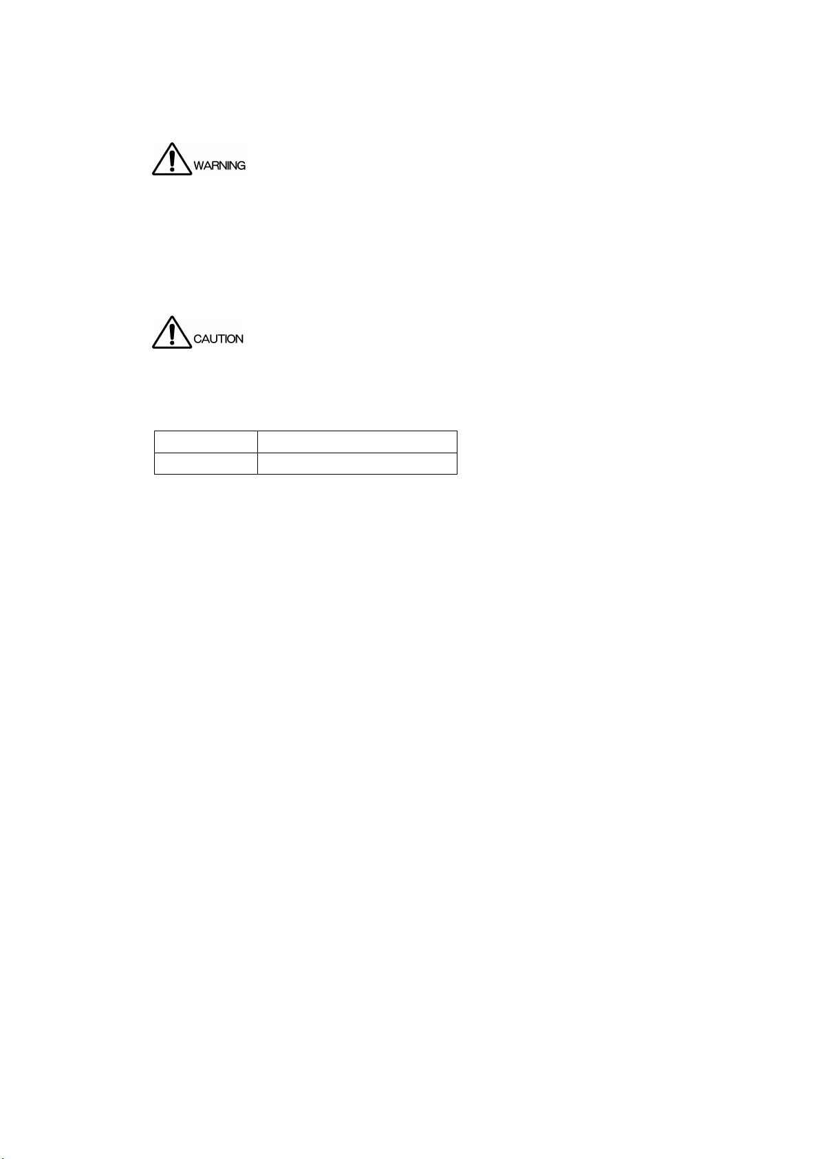
1.3.2 Maximum Allowable Input Voltage
The maximum signal voltage that can be applied to the input connectors is indicated below.
Do not apply excessive voltage to the connectors. Doing so may damage the device or
lead to injury.
Input Connector Maximum Allowable Input Voltage
GENLOCK IN ±5V (DC+ peak AC)
1.3.3 Mechanical Shock
This instrument contains sensitive components, so it may be damaged if it is dropped or
otherwise exposed to a strong shock.
1.3.4 Electrostatic Damage
Electronic components can be damaged by static discharge.
1.3.5 Warming Up
To ensure more accurate measurements, turn ON the instrument approximately 30 minutes
before you intend to use it to allow its internal temperature to stabilize.
1.3.6 About Power-on Settings
Last memory is not supported (except for the UTILITY SETTING). By setting POWER ON
RECALL, you can start the LT 4600A with preset settings.
1.4 About Terminology Used in this Manual
● Internal Mode
A state in which the genlock mode is set to INTERNAL. The internal reference signal is
used.
● Genlock Mode
A state in which the genlock mode is set to STAY-IN-SYNC. An external reference signal is
used.
● Input Format
The following names are used for the SDI signal input formats.
2
Page 13

1. INTRODUCTION
Name Description
SD SD-SDI
HD HD-SDI
HD(DL) HD-SDI dual link
3G-A 3G-SDI level A
3G-B 3G-SDI Level B
3G Collective term for 3G-A and 3G-B
● Logo App
Logo App is a software for converting bitmap data (*.bmp) into 4-level monochrome data
(*.lg) that can be used on the LT 4600A. It is in the included CD-ROM.
● About Underlining (_)
Underlined options indicate the default values.
3
Page 14

2. SPECIFICATIONS
2.1 General
The LT 4600A is a compact, 1U half-rack size SDI video signal generator that supports the
triple-rate SDI (3G/HD/SD) format. In addition to test pattern output including color bars and
SDI check fields, the LT 4600A is equipped with numerous features such as ID characters,
QVGA logo marks, safety area markers, audio embedding, genlock function for external
reference signals, and three analog black signals.
2.2 Features
● Triple-rate SDI Ready
Supports 3G (level A and level B), HD (including dual link), and SD.
The LT 4600A provides two outputs for two signals. The pattern and timing of each signal
can be adjusted separately. (However, only one signal can be used for 3G-B and HD (DL).)
● ID Character Overlay
ID characters can be overlaid at any position on the display. In addition, ID characters can
be scrolled horizontally or displayed in a blinking state for checking whether the display has
frozen.
● Logo Mark Overlay
2. SPECIFICATIONS
A logo mark up to 320 (dot) × 240 (line) in size (QVGA size) can be overlaid at any position
on the display. Logo marks are 4-level monochrome data converted from bitmap data.
● Safety Area Markers
90% and 80% safety area markers can be overlaid on the display. For 3G and HD, a 4:3
aspect marker can also
● Pattern Scrolling
Equipped with a function for scrolling patterns in eight directions. The speed can also be
adjusted.
● Audio Embedding
The LT 4600A can embed 32 channels (link A, link B, 4 channels each × 4 groups) of audio
signals for 3G-B and 16 channels (4 channels × 4 groups) of audio signals for 3G-A, HD,
and SD. The frequency, level, and the like can be set for each channel.
● Lip Sync Patterns
The LT 4600A can output lip sync patterns in which the video and audio are synchronized.
By using Leader’s LV 5770(A), you can accurately measure the lip sync of the video and
audio on SDI signals.
● Genlock Function
be overlaid.
The LT 4600A can synchronize with NTSC/PAL black burst signals and HD tri-level sync
signals.
NTSC/PAL black burst signal with field reference pulse and NTSC black burst signal with
10 field IDs are also supported.
Furthermore, a Stay-in-Sync function is available in case errors occur at the genlock input.
4
Page 15

2. SPECIFICATIONS
● Analog Black Output
Equipped with three independent black signals. The timing can be adjusted by selecting a
NTSC/PAL black burst signal or a HD tri-level sync signal whose clock frequency is the
same as in the SDI output format.
NTSC/PAL black burst signal with field reference pulse and NTSC black burst signal with
10 field IDs are also supported.
● Word-Clock Output
Equipped with one 48 kHz word-clock signal synchronized with video signals.
● AES/EBU Serial Digital Audio Output
Equipped with two 48 kHz AES/EBU signals synchronized with video signals.
● Ethernet
Standard support for SNMP makes it easy to integrate the LT 4600A in a network
environment.
● External Memory
Firmware updating and user data writing and saving are possible by connecting a USB
memory device on the front panel.
● Presets
Up to 10 presets can be saved. You can recall a preset to start the LT 4600A with the same
settings every time.
5
Page 16

2.3 Specifications
2.3.1 SDI Video Output
● SDI Electrical Characteristics
Bit Rate
3G 2.970 Gbps, 2.970/1.001 Gbps
HD, HD (DL) 1.485 Gbps, 1.485/1.001 Gbps
SD 270 Mbps
Output Amplitude 800 mVp-p ± 10%
Overshoot Less than 10%
Rise and Fall Times
3G ≤ 135 ps (20 to 80%)
HD, HD (DL) ≤ 270 ps (20 to 80%)
SD 0.4 ns to 1.5 ns (20 to 80%)
DC Offset 0 ± 0.5 V
Output Impedance 75 Ω
Return Loss ≥ 15 dB (5 MHz to 1.485 GHz)
Outputs Two signals two outputs (*1)
Output Connector BNC
*1 One signal two outputs for 3G-B. One signal one output for HD (DL).
The output settings can be specified separately for the two signals, but for 3G and HD, different frame
frequencies (60 Hz, 59.94 Hz, and 50 Hz) cannot be specified at the same time.
● Compliant Standards
2. SPECIFICATIONS
≥ 10 dB (1.485 to 2.970GHz)
3G-A SMPTE ST 274, SMPTE ST 296,
SMPTE ST 425
3G-B SMPTE ST 274, SMPTE ST 372,
SMPTE ST 425
HD (DL) SMPTE ST 274, SMPTE ST 372
HD SMPTE ST 274, SMPTE ST 292,
SMPTE ST 296、
SMPTE RP 211
SD SMPTE ST 125, SMPTE ST 259
SDI Embedded Audio
3G, HD, HD (DL) SMPTE ST 299
SD SMPTE ST 272
SDI Payload ID SMPTE ST 352
6
Page 17
2. SPECIFICATIONS
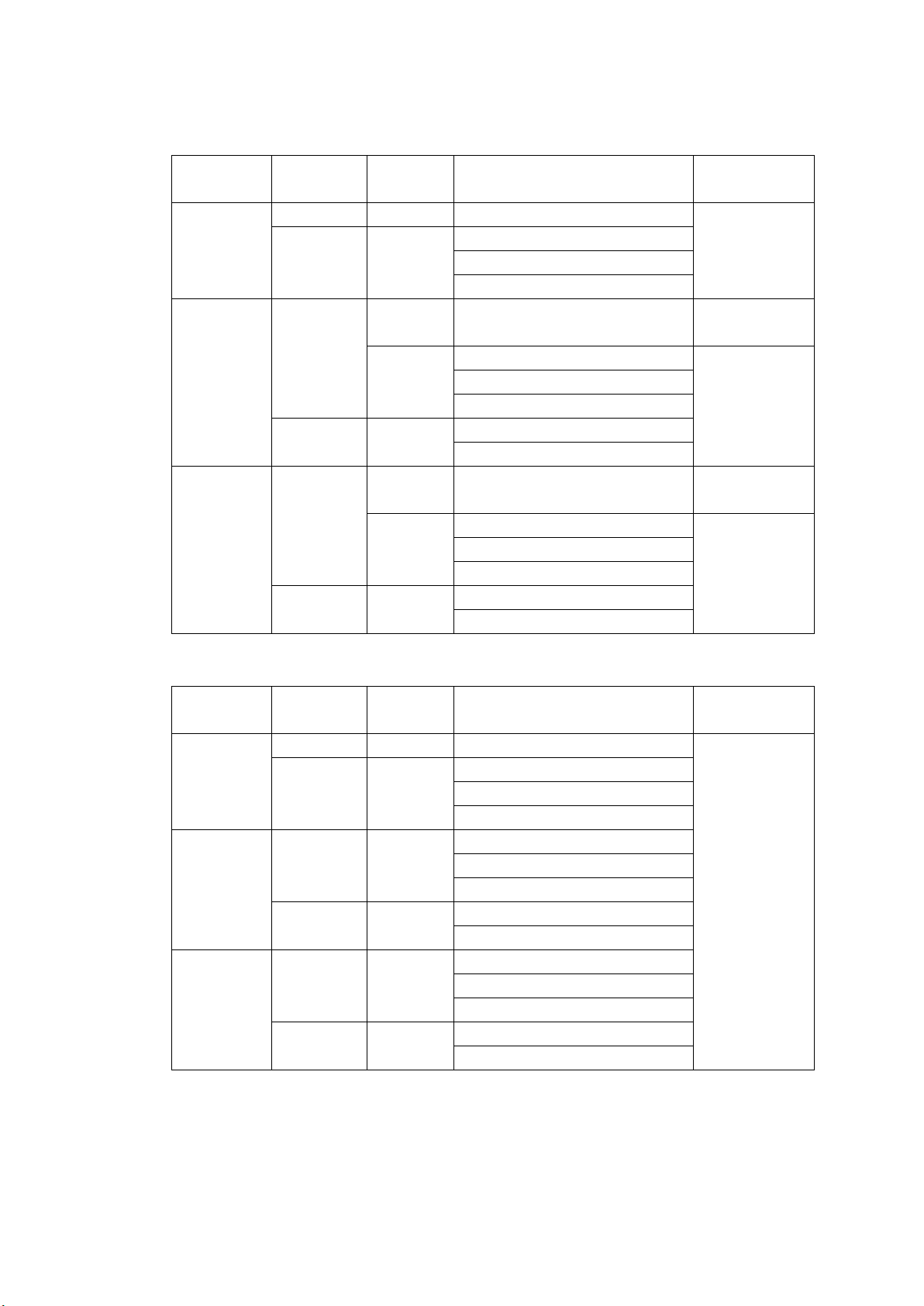
● Supported Formats
3G-A Formats and Standards
Color System Quantization Image Frame (Field) Frequency/Scanning Compliant
Standards
YCBCR 4:2:2 10 bits 1920×1080 60/59.94/50/P SMPTE ST 274
12 bits 1920×1080 60/59.94/50/I
30/29.97/25/24/23.98/P
30/29.97/25/24/23.98/PsF
YCBCR 4:4:4 10 bits 1280×720 60/59.94/50/30/29.97/25/24/23.98/P SMPTE ST 296
1920×1080 60/59.94/50/I SMPTE ST 274
30/29.97/25/24/23.98/P
30/29.97/25/24/23.98/PsF
12 bits 1920×1080 60/59.94/50/I
30/29.97/25/24/23.98/P
RGB 4:4:4 10 bits 1280×720 60/59.94/50/30/29.97/25/24/23.98/P SMPTE ST 296
1920×1080 60/59.94/50/I SMPTE ST 274
30/29.97/25/24/23.98/P
30/29.97/25/24/23.98/PsF
12 bits 1920×1080 60/59.94/50/I
30/29.97/25/24/23.98/P
SMPTE ST 425
SMPTE ST 425
SMPTE ST 425
SMPTE ST 425
SMPTE ST 425
3G-B Formats and Standards
Color System Quantization Image Frame (Field) Frequency/Scanning Compliant
Standards
YCBCR 4:2:2 10 bits 1920×1080 60/59.94/50/P SMPTE ST 274
12 bits 1920×1080 60/59.94/50/I
30/29.97/25/24/23.98/P
30/29.97/25/24/23.98/PsF
YCBCR 4:4:4 10 bits 1920×1080 60/59.94/50/I
30/29.97/25/24/23.98/P
30/29.97/25/24/23.98/PsF
12 bits 1920×1080 60/59.94/50/I
30/29.97/25/24/23.98/P
RGB 4:4:4 10 bits 1920×1080 60/59.94/50/I
30/29.97/25/24/23.98/P
30/29.97/25/24/23.98/PsF
12 bits 1920×1080 60/59.94/50/I
30/29.97/25/24/23.98/P
SMPTE ST 372
SMPTE ST 425
7
Page 18
2. SPECIFICATIONS
HD (DL) Formats and Standards
Color System Quantization Image Frame (Field) Frequency/Scanning Compliant
Standards
YCBCR 4:2:2 10 bits 1920×1080 60/59.94/50/P SMPTE ST 274
12 bits 1920×1080 60/59.94/50/I
30/29.97/25/24/23.98/P
30/29.97/25/24/23.98/PsF
YCBCR 4:4:4 10 bits 1920×1080 60/59.94/50/I
30/29.97/25/24/23.98/P
30/29.97/25/24/23.98/PsF
12 bits 1920×1080 60/59.94/50/I
30/29.97/25/24/23.98/P
30/29.97/25/24/23.98/PsF
RGB 4:4:4 10 bits 1920×1080 60/59.94/50/I
30/29.97/25/24/23.98/P
30/29.97/25/24/23.98/PsF
12 bits 1920×1080 60/59.94/50/I
30/29.97/25/24/23.98/P
30/29.97/25/24/23.98/PsF
SMPTE ST 372
HD and SD Formats and Standards
Color System Quantization Image Frame (Field) Frequency/Scanning Compliant
Standards
YCBCR 4:2:2 10 bits 1280×720 60/59.94/50/30/29.97/25/24/23.98/P SMPTE ST 292
SMPTE ST 296
1920×1080 60/59.94/50/I SMPTE ST 292
30/29.97/25/24/23.98/P
24/23.98/PsF SMPTE ST 292
720×487 59.94/I SMPTE ST 259
720×576 50/I
SMPTE ST 274
SMPTE RP 211
SMPTE ST 125
8
Page 19

2. SPECIFICATIONS
● Timing Adjustment
Adjustment Range Entire frame
Adjustment Unit
V Lines
H Clocks (148.5 MHz, 148.5/1.001 MHz, 74.25
MHz, 74.25/1.001 MHz, 27 MHz)
● Test Patterns
3G, HD 100% color bar, 75% color bar,
multiformat color bar (ARIB STD-B28, pattern 2
area can be set to 100% white, 75% white, or
+I), check field,
blue field 100%, green field 100%,
red field 100%,
flat field white 100%, black 0%
SD
525i/59.94 100% color bar, 75% color bar,
SMPTE color bar, check field,
blue field 100%, green field 100%,
red field 100%,
flat field white 100%, black 0%
625i/50 100% color bar, EBU color bar,
BBC color bar, check field,
blue field 100%, green field 100%,
red field 100%,
flat field white 100%, black 0%
Automatic Switching Automatically switches between available
patterns (except for check field)
Switch Time 1 to 255 sec
● Pattern Scrolling
Direction Eight directions (up, down, left, right, and their
combinations)
Speed Range and Unit
Interlace In unit of fields
V 0 to 256 lines, in 1 line steps
H 0 to 256 dots, in 2 dot steps
Progressive In unit of frames
V 0 to 256 lines, in 1 line steps
H 0 to 256 dots, in 2 dot steps
* Not available when the check field pattern is selected.
● Safety Area Markers
HD Action safe area (90%)
3G,
Title safe area (80%)
4:3 aspect ratio
9
Page 20

2. SPECIFICATIONS
(can be turned on and off separately)
SD Action safe area (90%)
Title safe area (80%)
(can be turned on and off separately)
* Not available when the check field pattern is selected.
10
Page 21

2. SPECIFICATIONS
● ID Characters
Number of Characters Up to 20 characters
Size [Dots] 32×32, 64×64, 128×128, 256×256
Intensity 100%, 75% (black only for the background
color)
Display Position Anywhere on the display
Display Position Adjustment Resolution
V 1 line
H 1 dot
Blinking Display (*1) O F F, 1 to 9 sec
Scrolling (*1)
Function Scroll including the ID character background
Direction Two directions (left and right)
Speed Range and Unit
Interlace In unit of fields
0 to 256 dots, in 2 dot steps
Progressive In unit of frames
0 to 256 dots, in 2 dot steps
* Not available when the check field pattern is selected.
*1 The blinking display and scrolling can be used simultaneously.
● Logo Mark
Logo Mark Data 4-level monochrome data from level 0 to 3
Maximum Size 320 (dots) × 240 (lines) (QVGA size)
Number of Logo Marks That Can Be Saved in the LT 4600A
Up to 4
Display Position Anywhere on the display
Display Position Adjustment Resolution
V 1 line
H 1 dot
Display Level Any level from 0 to 3
File Format
Before Conversion 24-bit full color bitmap format (.bmp)
After Conversion Original format (.l
g)
Conversion Color Matrix Y = (0.212×R) + (0.701×G) + (0.087×B)
Converts 256-level monochrome data (Y) to 4
levels (levels 0 to 3) using specified thresholds
Conversion Method Using the logo application
Logo Mark Data Transfer Save the data to a USB memory device and
transfer to the LT 4600A.
* Not available when the check field pattern is selected.
11
Page 22

2. SPECIFICATIONS
● Channel On/Off
Function Each of the Y/G, Cb/B, and Cr/R components
can be turned on and off for each channel
independently.
On Outputs the specified Y/G, Cb/B, or Cr/R signal
Off
Y/G 040h/000h
Cb/B 200h/000h
Cr/R 200h/000h
* Not available when the check field pattern is selected.
* Black pattern can be output by turning off all channels and all embedded audio signals.
● Image Overlay
Display Precedence ID characters > logo mark > safety area
markers > test pattern
(The display order cannot be changed.)
Simultaneous Display ID characters, logo mark, safety area markers,
and test pattern can be displayed
simultaneously.
● Embedded Audio
Embedded Channels Can be turned on and off at the group level
3G-A, HD, SD 16 channels (4 channels × 4 groups)
3G-B 32 channels (link A, link B, 4 channels each × 4
groups)
Sampling Frequency 48 kHz sampling (synced with the video signal)
Resolution 20 bits, 24 bits
Pre-emphasis OFF, 50/15, CCITT (only the CS bit is switched)
Frequency SILENCE, 400 Hz, 800 Hz, 1 kHz
Level -60 to 0 dBFS (1 dBFS steps)
Audio Click OFF, 1 to 4 sec
* Audio (including packets) cannot be embedded when the check field pattern is selected.
* The frequency, level, and audio click can be set for each channel.
* The following limitations apply for SD (525i/59.94).
• For 16 channel output, the resolution is set to 20 bits.
• Up to three groups (12 channels) can be output at 24-bit resolution.
● Lip Sync Patterns
Supported Formats 3G, HD, HD (DL), SD
Value On, Off
* Not available when the check field pattern is selected.
* Safety area markers, ID characters, and logo mark cannot be overlaid.
* The audio click setting of embedded audio is disabled, and audio synchronized to the lip sync pattern
is output.
12
Page 23

2.3.2 Genlock Function
External Reference Input
Format BNC 75 Ω loop-through
Compliant Standards
NTSC Black Burst Signal SMPTE RP 154, SMPTE ST 170,
PAL Black Burst Signal EBU N14, ITU-R BT 1700
HD Tri-Level Sync Signal SMPTE ST 240, SMPTE ST 274,
Sync Level
NTSC Black Burst Signal -286 mV
PAL Black Burst Signal -300 mV
HD Tri-Level Sync Signal ±300 mV
Operation Mode
Internal Operates using the internal signal
Stay-in-Sync Holds the last genlock input frequency when
2.3.3 Analog Black Output
2. SPECIFICATIONS
SMPTE ST 318
SMPTE ST 296
the signal is interrupted
Compliant Standards
NTSC Black Burst Signal SMPTE RP 154, SMPTE ST 170,
SMPTE ST 318
PAL Black Burst Signal EBU N14, ITU-R BT 1700
HD Tri-Level Sync Signal SMPTE ST 240, SMPTE ST 274,
SMPTE ST 296
Output Signal
Outputs 6 (3 signals × 2 outputs)
Output Format Setting Each of the three signals can be configured
independently.
Output Impedance 75 Ω
Output Connector BNC
Timing Adjustment
Value Each of the three signals can be configured
independently.
Adjustment Range
NTSC Black Burst Signal ±5 frames
PAL Black Burst Signal ±2 frames
HD Tri-Level Sync Signal 1 frame (entire frame)
Adjustment Unit
NTSC/PAL Black Burst Signal In units of 0.0185 μs (54 MHz clock unit)
HD Tri-Level Sync Signal In
units of 0.0135 μs (74.25/1.001 MHz clock
unit or 74.25 MHz clock unit)
* HD tri-level sync signal of 3G format (1080p) cannot be output.
* The output settings can be specified separately for the three signals, but for HD tri-level sync signal,
different frame frequencies (60 Hz, 59.94 Hz, and 50 Hz) cannot be specified at the same time.
13
Page 24

2.3.4 Word-Clock Output
Output Frequency 48 kHz
Output Amplitude 5V CMOS Compatible (when not terminated)
Output Connector BNC
Outputs 1
Timing Adjustment
Adjustment Range ±1 AES/EBU frame
Adjustment Unit 512 fs (24.576 MHz)
2.3.5 AES/EBU Digital Audio Output
Compliant Standards ANSI S4.40, AES3-2009, AES11-2009,
Output Impedance 75 Ω unbalanced
Output Amplitude 1 Vp-p ± 0.1 V
Output Connector BNC
Outputs 2 (each 2 channel pair)
Timing Adjustment
Adjustment Range ±1 AES/EBU frame
Adjustment Unit 512 fs (24.576 MHz)
Sampling Frequency 48 kHz sampling (synced with the video signal)
Resolution 20 bits, 24 bits
Pre-emphasis OFF, 50/15, CCITT (only the CS bit is switched)
Frequency SILENCE, 400 Hz, 800 Hz, 1 kHz
Level -60 to 0 dBFS (1 dBFS steps)
Audio Click OFF, 1 to 4 sec
Lip Sync ENABLE, DISABLE
Sampling Clock Accuracy Grade 2 (±10 ppm)
* The frequency, level, and audio click can be set for each channel.
(When lip sync is enabled, the audio click setting is disabled, and audio synchronized to the lip sync
pattern is output.)
* Turn off all channels to output a digital audio reference signal (DARS).
2.3.6 External Interface
2. SPECIFICATIONS
SMPTE ST 276
Ethernet
Specifications 10BASE-T/100BASE-TX auto switching
Function Transmission of operation status (e.g., genlock
synchronization status)
SNMP v1 compliant
USB
Connector USB Type
A
Specifications USB 2.0
Supported Media USB memory device (up to 8 GB)
Function Saving and loading of preset data
saving and loading of logo data
updating of firmware
14
Page 25

2.3.7 Presets
Presets Saves the panel settings (*1)
Number of Presets 10
Recall Method Front panel
Copy Method Copy all presets from the LT 4600A to a USB
* Last memory is not supported. By setting POWER ON RECALL, you can start the LT 4600A with
preset settings.
*1 Logo data and device-specific information (e.g., IP address, time) cannot be saved.
2.3.8 LCD
Number of Characters 20 characters × 2 lines
Backlight On, Off
2.3.9 General Specifications
2. SPECIFICATIONS
memory device or copy all presets from the
USB memory device to the LT 4600A
Environmental Conditions
Operating Temperature 0 to 40 °C
Operating Humidity Range 85 %RH or less (no condensation)
Optimal Temperature 10 to 35 °C
Operating Environment Indoors
Elevation Up to 2,000 m
Overvoltage Category ǁ
Pollution Degree 2
Power Requirements
Voltage 90 to 250 VAC
Power Consumption 25W max.
Dimensions 213 (W) × 44 (H) × 400 (D) mm (excluding
protrusions)
Weight 3.0kg
Accessories Power cord ....................................................... 1
Cover/Inlet stopper ........................................... 1
CD-ROM (Logo App, instruction manual) ........ 1
Sold Separately LR 2478 (rack mount adapter for two units)
LR 2481 (rack mount adapter for one unit)
15
Page 26
3. PANEL DESCRIPTION
3.1 Front Panel
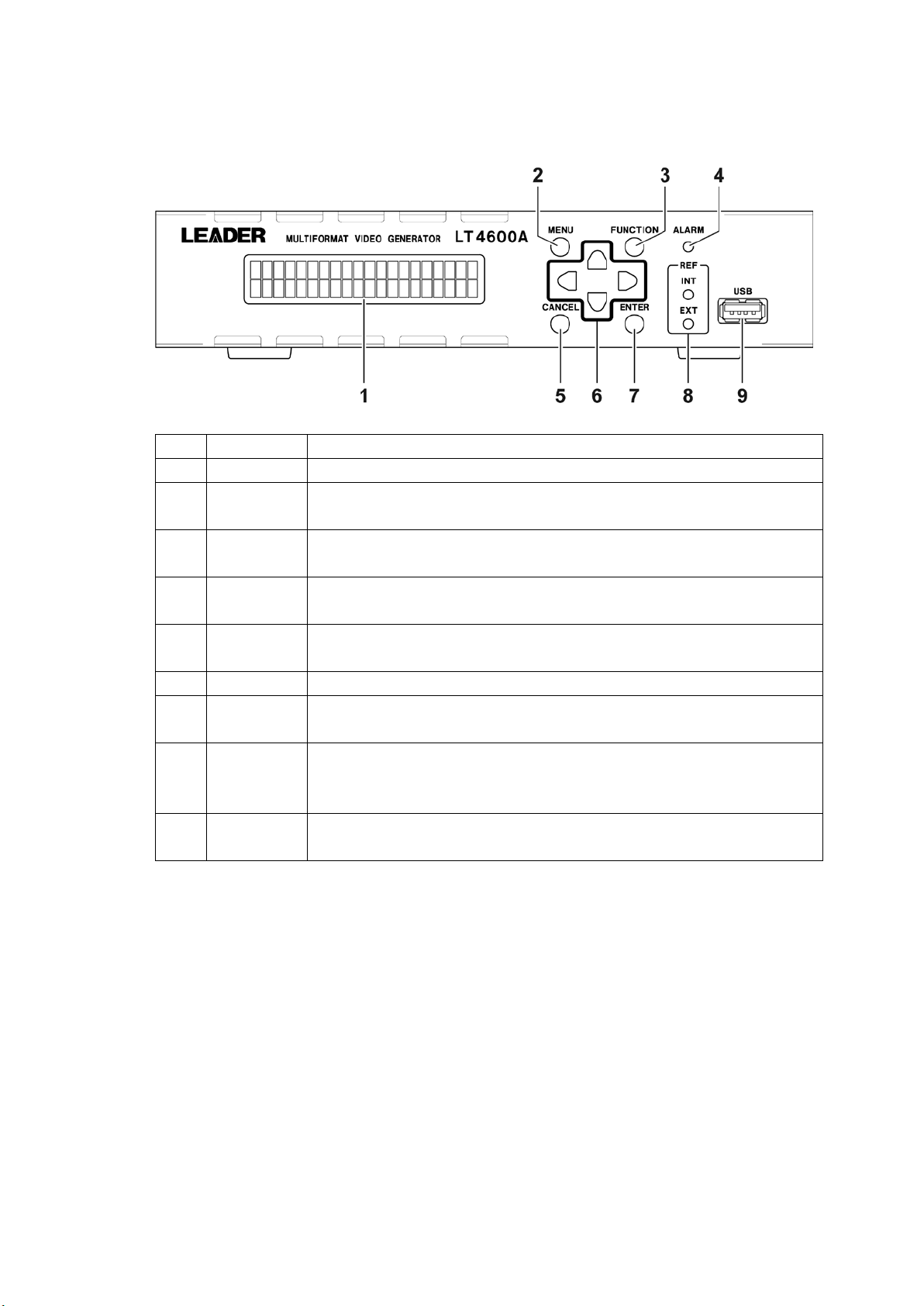
No. Name Description
1 LCD Shows various information.
2 MENU Switches the menu.
See section 4.5, “Menu Operations.”
3 FUNCTION Enables and disables the key lock.
See section 6.2, “Turning Key Lock On and Off.”
4 ALARM Blinks when the fan stops.
See section 4.3, “Alarm Indications.”
5 CANCEL Cancels settings.
See section 4.5, “Menu Operations.”
6 Arrow keys Used to move the cursor and to set values.
7 ENTER Confirms settings.
See section 4.5, “Menu Operations.”
8 REF INT lights when the internal reference signal is in use. EXT lights or blinks when
an external reference signal is in use.
See section 5.1, “Genlock Status Display.”
9 USB USB port. Used to save and load various data and update the firmware.
See section 4.4, “Connecting a USB Memory Device.”
3. PANEL DESCRIPTION
16
Page 27
3.2 Rear Panel
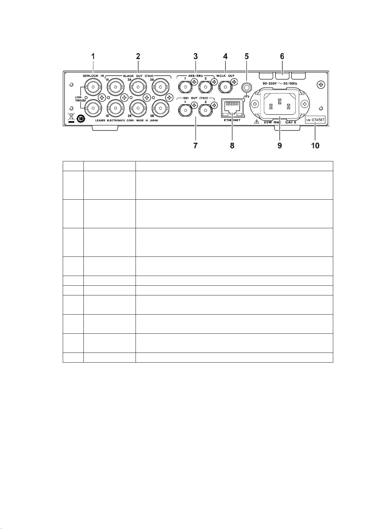
No. Name Description
1 GENLOCK IN Genlock input connectors. They are loop-through connectors.
2 BLACK OUT Black output connectors.
3 AES/EBU AES/EBU digital audio output connector.
4 WCLK OUT 48 kHz word-clock output connector.
5 Ground terminal Connect the instrument to an external ground.
6 Fan Cooling fan for the instrument.
7 SDI OUT SDI output connectors. Outputs SD, HD, and 3G signals.
8 ETHERNET Ethernet port. Used to remotely monitor the LT 4600A status.
9 AC inlet Attach the included cover/inlet stopper to the AC inlet.
10 Serial label The serial number is printed on this label.
3. PANEL DESCRIPTION
They receive HD tri-level sync or NTSC/ PAL black burst signals.
See chapter 7, “GENLOCK FUNCTION (REFERENCE SETTING.)”
They output HD tri-level sync or NTSC/PAL black burst signals.
See chapter 9, “ANALOG BLACK OUTPUT (BLACK SETTING).”
See chapter 11, “AES/EBU DIGITAL AUDIO OUTPUT (AES/EBU
SETTING).”
See chapter 12, “WORD-CLOCK OUTPUT (WCLK SETTING).”
See chapter 10, “SDI Output (SDI SETTING).”
See chapter 13, “SNMP.”
[See also] 4.1, “Attaching the Cover Inlet Stopper”
17
Page 28
4. BEFORE USE
4. BEFORE USE
4.1 Attaching the Cover Inlet Stopper
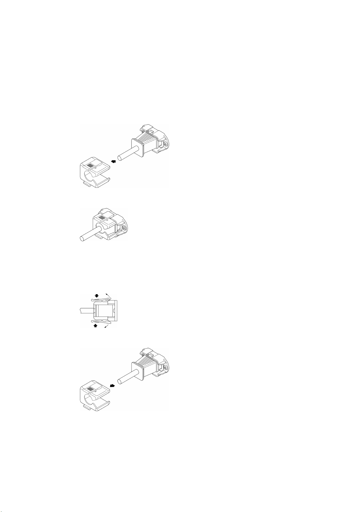
A cover/inlet stopper is included with the LV 7390. Use this device to prevent the power cord
from being pulled free of the AC inlet. To attach the cover/inlet stopper, follow the procedure
below.
● Attaching the Cover/Inlet Stopper
1. Cover the power cord with the cover/inlet stopper.
2. Push the cover/inlet stopper, until you hear a click, to attach it to the AC inlet.
3. Check that the cover/inlet stopper is securely attached to the AC inlet.
● Removing the Cover/Inlet Stopper
1. Release the lock by using two fingers to press the cover/inlet stopper levers.
2. Pull the cover/inlet stopper away from the AC inlet.
18
Page 29

4.2 Turning the Power On
● Turning the Power On
The LT 4600A does not have a power switch. Simply connect the power cord.
● Starting
When the power turns on, the LT 4600A starts to initialize. During initialization, signals are
not output, and you cannot use the keys.
● Startup Complete
4. BEFORE USE
When the following screen appears, the startup is complete.
● Power-on Settings
See section 14.1, “List of Settings.”
4.3 Alarm Indications
If an error occurs in the fan, the ALARM LED on the front panel blinks in red.
If this happens, contact your local LEADER agent.
19
Page 30
4. BEFORE USE
*USB STORAGE DEVICE*
* INSERT *
*USB STORAGE DEVICE*
* EJECT *
LT4600A LOCK STATUS
[ INTERNAL ]
0.UTILITY SETTING
LCD BACK LIGHT ↵
0.REFERENCE SETTING
GENLOCK MODE ↵
0.SYSTEM SETTING
SYSTEM SELECT ↵
0.BLACK SETTING
BLACK1 SIGNAL
0.SDI SETTING
SDI 1(3G-SDI-LvA)
0.AES/EBU SETTING
AES/EBU 1
0.WCLK SETTING
WCLK TIMING ↵
4.4 Connecting a USB Memory Device
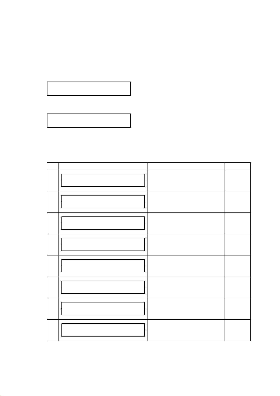
To import and export various data, you can use a USB memory device.
Use a USB memory device whose capacity is 8 GB or less. You can connect and disconnect
a USB memory device with the power turned on.
When you connect a USB memory device, the following message appears.
Do not turn the power off or remove the USB memory device while it is being accessed.
When you remove the USB memory device, the following message appears.
4.5 Menu Operations
There are eight main types of menus that appear on the LCD. The menu switches each time
you press the MENU key (when the menu level is at zero).
No. Menu Description Reference
1
Displays the genlock status and the
current main settings.
Chapter 5
2
Configure the backlight and other LT
Chapter 6
4600A settings.
3
Set the genlock. Chapter 7
4
Configure the frequency groups and
Chapter 8
other LT 4600A settings.
5
Set the black signal. Chapter 9
6
Set the SDI signal. Chapter 10
7
Set the AES/EBU signal. Chapter 11
8
Set the word-clock signal. Chapter 12
20
Page 31
4. BEFORE USE
0.UTILITY SETTING
LCD BACK LIGHT ↵
CANCEL
ENTER
1.LCD BACK LIGHT
■ON □OFF
1.WCLK TIMING
0 (512fs)
2.IP ADDRESS
192
.168.000.000
1.LCD BACK LIGHT
■ON □OFF
4.AUDIO ON/OFF
*■G1 ■G2 ■G3 ■G4
3.PATTERN SELECT
*COLOR BAR 75%
3.PATTERN SELECT
!SMPTE COLOR BAR
● Menu Levels
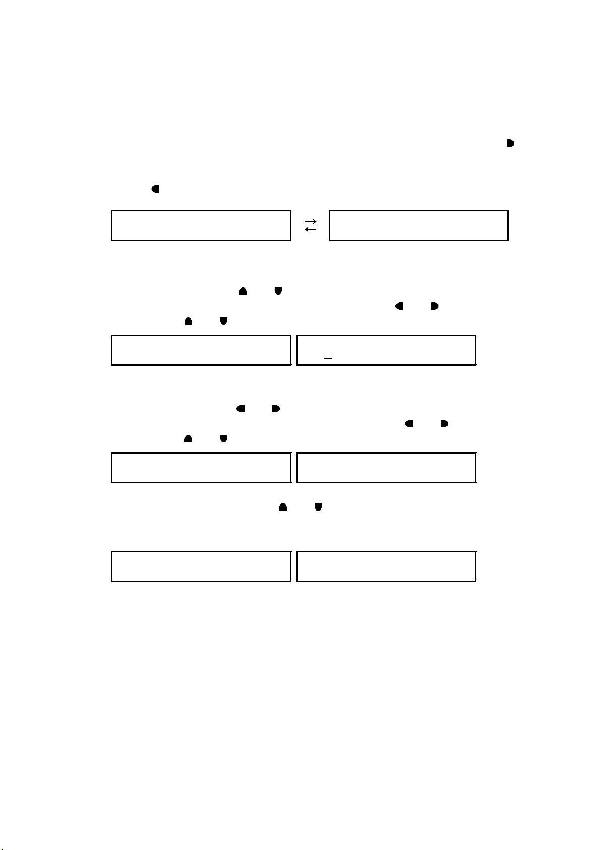
With the exception of a portion of the screens, the settings menus show a number to the
upper left of the screen. This number indicates the menu level. The larger the number, the
deeper the level.
To enter a lower level menu, press ENTER. (In some screens, you can also use the
key. )
To return to a higher level menu, press CANCEL or MENU. (In some screens, you can also
use the
k ey.)
● Specifying Values
To change values, use the
If a cursor (_) is displayed such as in IP ADDRESS, use the
cursor and the
and keys to change the value.
and keys. Hold down a key to change the number quickly.
and keys to move the
● Selecting Items
To select an item, use the
If a cursor (*) is displayed such as in AUDIO ON/OFF, use the
cursor and the
and keys to switch between on and off.
and keys.
and keys to move the
Some items are selected using the
and keys.
When you press the ENTER key to confirm the value, an asterisk appears to the left of the
item. An exclamation mark indicates that the item cannot be selected.
● Confirming and Canceling Settings
Press ENTER on a setting screen to confirm the setting. Press CANCEL to cancel the
setting.
For some items, the setting is immediately confirmed. Pressing CANCEL will not revert the
setting to the previous value.
21
Page 32
5. STATUS DISPLAY (STATUS)
LT4600A LOCK STATUS
[ INTERNAL ]
LT4600A LOCK STATUS
[ NO SIGNAL ]
LT4600A LOCK STATUS
[ TRACKING FAST ]
LT4600A LOCK STATUS
[ EXTERNAL ]
LT4600A LOCK STATUS
[ STAY-IN-SYNC ]
5. STATUS DISPLAY (STATUS)
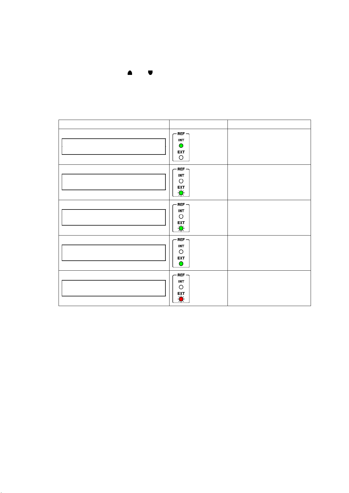
The STATUS display shows the genlock status and the current main settings. This screen is
only for viewing; you cannot change the settings.
To switch screens, use the
5.1 Genlock Status Display
LT 4600A LOCK STATU S displays the genlock status.
This section will explain the display details in conjunction with the REF display.
Screen Reference display Description
and keys.
[INT]
Lit in green
[EXT]
Blinking
green (fast)
[EXT]
Blinking
green (slow)
[EXT]
Lit in green
Internal mode
Genlock mode, no input signal
Genlock mode, drawing in the
reference signal
Genlock mode, normal operation
[EXT]
Blinking red
Genlock mode, reference signal
error
(Stay-in-sync in operation)
22
Page 33
5.2 Genlock Setting Display
[STATUS] GENLOCK ST
INTERNAL
[STATUS] BLACK 1
1080i/59.94
[STATUS] BLACK 2
1080i/59.94
[STATUS] BLACK 3
1080i/59.94
[STATUS] OUTPUT MODE
1:3G-LvA 2:3G-LvA
[STATUS] SDI1 FORMAT
1080p/59.94
[STATUS] SDI1 SAMPLE
422(YCbCr) 10bit
[STATUS] SDI2 FORMAT
1080p/59.94
[STATUS] SDI2 SAMPLE
422(YCbCr) 10bit
[STATUS] SDI1 PATT
COLOR BAR 100%
[STATUS] SDI2 PATT
COLOR BAR 100%
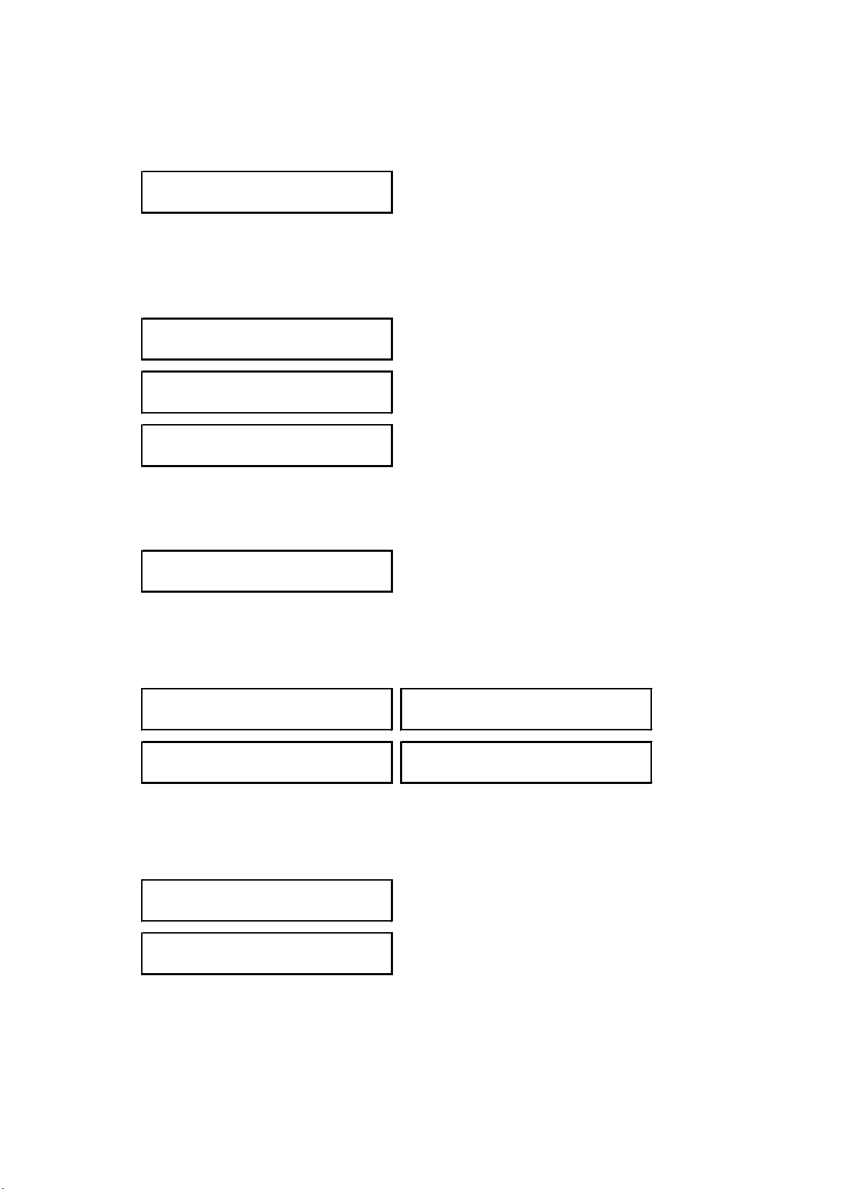
GENLOCK ST displays the genlock mode selected in section 7.2, “Selecting the Genlock
Mode.”
5.3 Black Setting Display
BLACK 1, BLACK 2, and BLACK 3 display the black format selected in section 9.1, “Selecting
the Black Format.”
5. STATUS DISPLAY (S TATUS)
5.4 SDI Setting Display
OUTPUT MODE displays the SDI output set in section 8.3, “Selecting the SDI Output Signal.”
SDI1 FO R M AT, SDI1 SAMPLE, SDI2 F O R MAT, and SDI2 SAMPLE display the SDI format
selected in section 10.1, “Selecting the SDI Format.”
If the SDI output is 3G-B or HD (DL), SDI FORMAT and SDI SAMPLE will be displayed.
SDI1 PATT and SDI2 PATT display the SDI pattern selected in section 10.2.1, “Selecting the
Pattern.”
If the SDI output is 3G-B or HD (DL), SDI PATT will be displayed.
23
Page 34
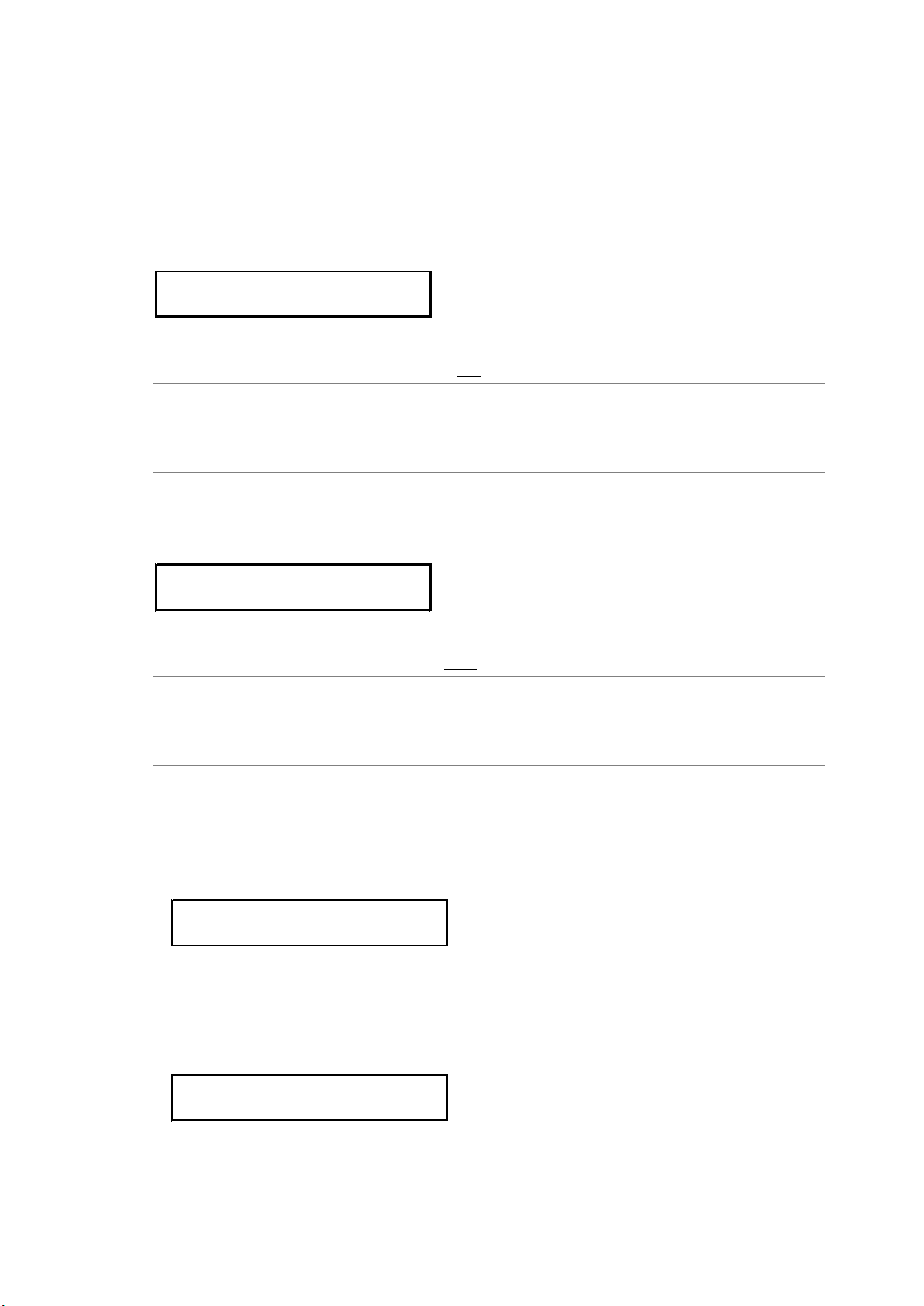
6. LT 4600A CONFIGURATION (UTILITY SETTING)
1.LCD BACK LIGHT
■ON □OFF
1.KEY LOCK
■ON □OFF
* KEY LOCK *
PUSH <FUNCTION> 3SEC
* KEY LOCK *
* UNLOCK SUCCESS *
6. LT 4600A CONFIGURATION (UTILITY SETTING)
UTILITY SETTING is used to configure the basic LT 4600A settings.
These settings are not stored to presets.
6.1 Turning the Backlight On and Off
To turn the LCD backlight on or off, follow the procedure below.
Procedure
UTILITY SETTING → LCD BACK LIGHT: ON / OFF
Settings
ON: The backlight is turned on.
OFF: The backlight is turned off.
6.2 Turning Key Lock On and Off
To turn key lock on and off, follow the procedure below.
Procedure
UTILITY SETTING → KEY LOCK: ON / OFF
Settings
ON: Key lock is enabled.
OFF: Key lock is disabled.
● Behavior When Key Lock Is Enabled
The LT 4600A locks its keys after 30 seconds of inactivity (no key operations).
When the keys are locked, all keys are disabled. If you press a key in this condition, the
following message is displayed for about 3 seconds.
When key lock is enabled, you can temporarily disable key lock by holding down
FUNCTION for 3 seconds. (The LT 4600A will lock its keys again after 30 seconds of
inactivity or if you hold down FUNCTION for 3 seconds.)
Release the key when the following message appears.
24
Page 35
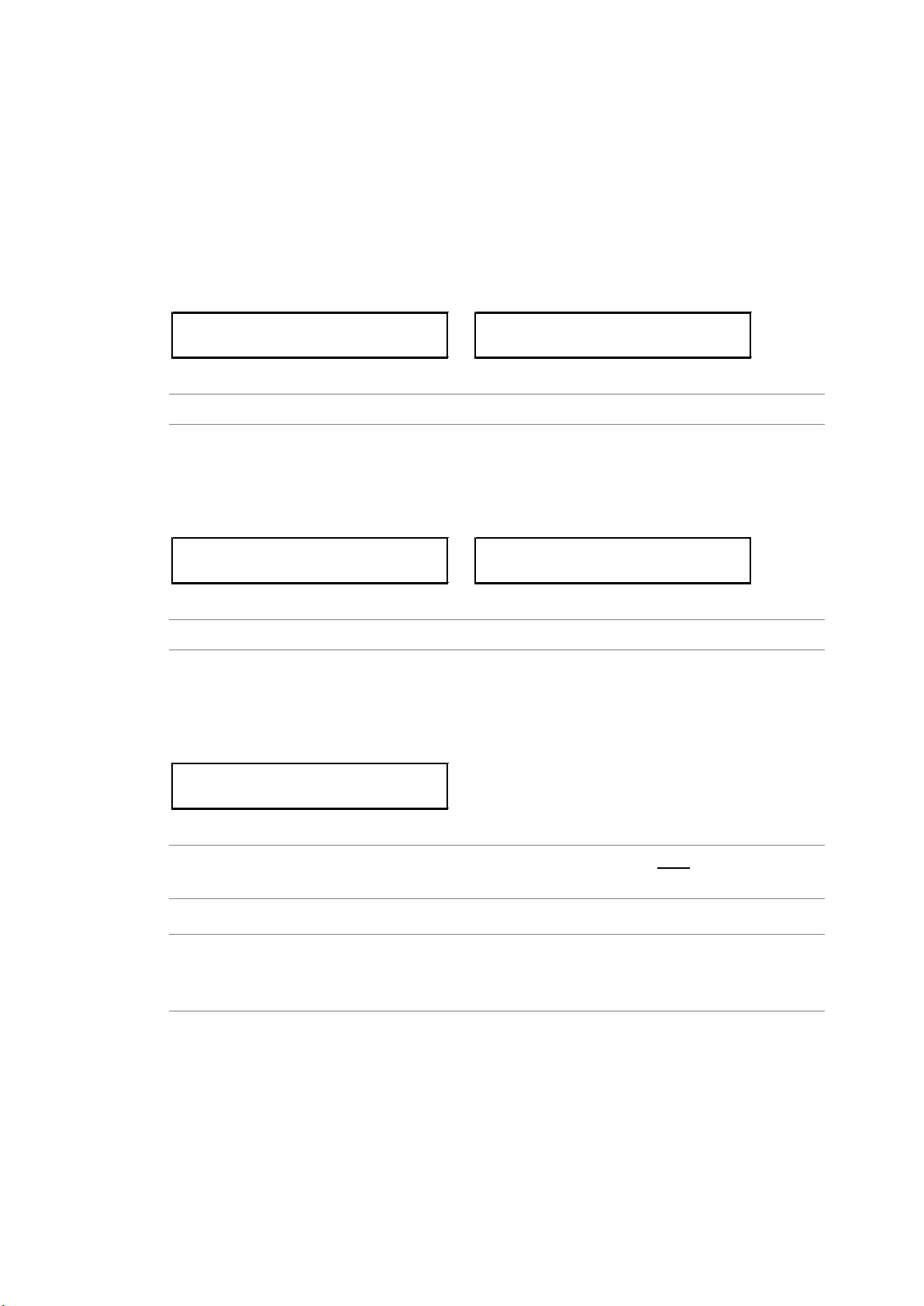
6. LT 4600A CONFIGURATION (UTILITY SETTING)
2.PRESET
NUMBER 0
NUMBER 0 PRESET ?
■OK □CANCEL
2.RECALL
NUMBER 0
NUMBER 0 RECALL ?
■OK □CANCEL
2.POWER ON RECALL
*OFF
6.3 Configuring Presets
Presets contain LT 4600A settings that you registered. Presets can be imported and exported
through a USB memory device. A preset can be recalled automatically at startup.
6.3.1 Saving Presets
You can save up to 10 presets by following the procedure below. For details on what is
saved in presets, see section 14.1, “List of Settings.”
By factory default, NUMBER 0 to NUMBER 9 contain factory default values.
Procedure
UTILITY SETTING → PRESET/RECALL → PRESET: NUMBER 0 - NUMBER 9
6.3.2 Recalling Presets
To recall a preset that you saved according to the procedure in section 6.3.1, “Saving
Presets,” follow the procedure below.
Procedure
UTILITY SETTING → PRESET/RECALL → RECALL: NUMBER 0 - NUMBER 9
6.3.3 Power-on Settings
To select the preset to use for starting the LT 4600A, follow the procedure below. For
details, see section 14.1, “List of Settings.”
Procedure
UTILITY SETTING → PRESET/RECALL → POWER ON RECALL: OFF / NUMBER 0 -
NUMBER 9
Settings
OFF: The LT 4600A starts with factory default settings.
NUMBER 0 - NUMBER 9:
The LT 4600A starts with the selected preset.
25
Page 36
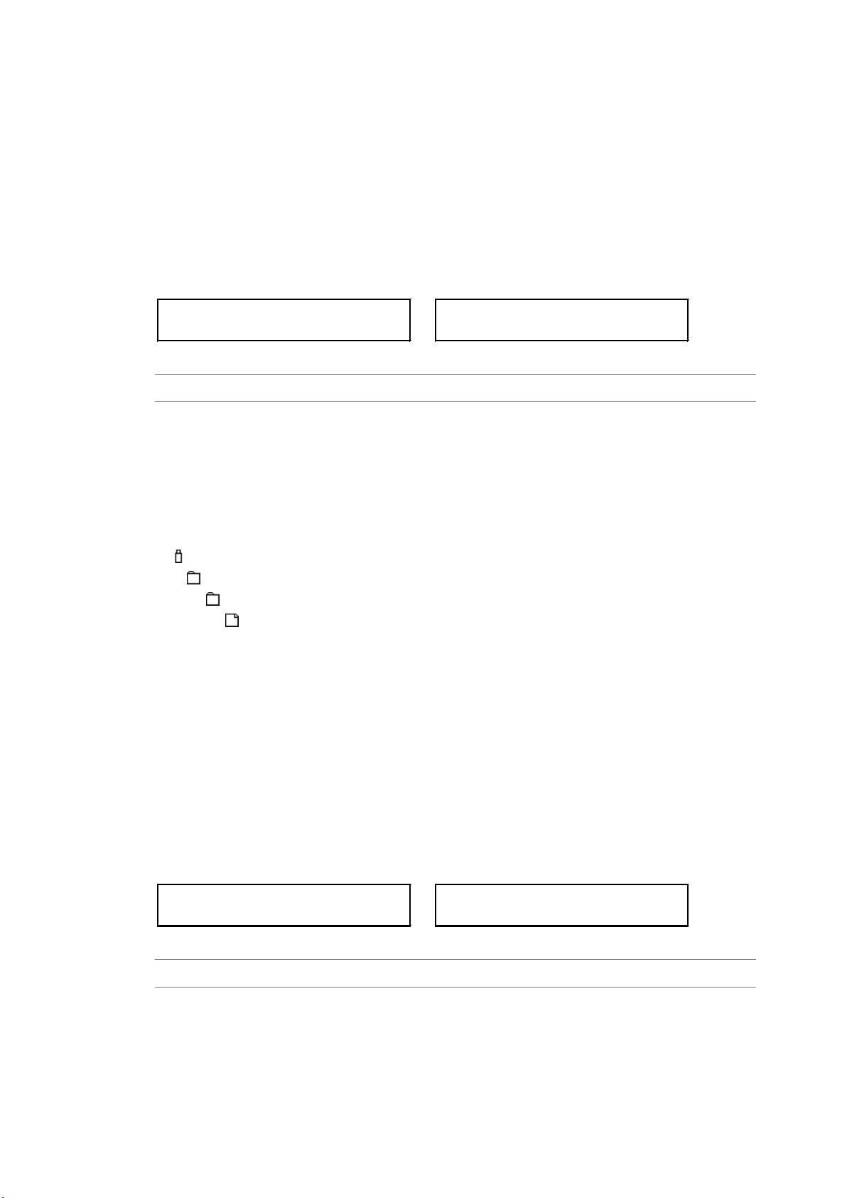
6. LT 4600A CONFIGURATION (UTILITY SETTING)
3.EXPORT TO USB
■OK □CANCEL
EXPORT TO USB
■■■■■■■■□□□□□□□ 50%
IMPORT FROM USB
■■■■■■■■□□□□□□□ 50%
3.IMPORT FROM USB
■OK □CANCEL
6.3.4 Exporting the Presets
To export the presets from the LT 4600A to a USB memory device, follow the procedure
below. This feature is useful when you want to use multiple LT 4600As with the same
settings.
All 10 presets are exported to a single file. You cannot export individual presets.
While the presets are being exported, an indicator appears to show the progress. When the
original screen returns, exporting is finished. Do not turn the power off or remove the USB
memory device until the original screen returns.
Procedure
UTILITY SETTING → PRESET/RECALL → IMPORT/EXPORT → EXPORT TO USB
● USB Memory Device File Structure
The presets are exported to the PRESET folder in the USB memory device. If a file
already exists, it is overwritten.
The date and time of the exported file will be the date and time specified according to the
procedure in section 6.6, “Setting the Date and Time.”
USB memory device
LT4600A
└
└
└
PRESET
LT4600A_PRESET_DATA.DAT
6.3.5 Importing Presets
To import the presets that have been exported according to the procedure in section 6.3.4,
“Exporting the Presets” from the USB memory device to the LT 4600A, follow the
procedure below. This feature is useful when you want to use multiple LT 4600As with the
same settings.
All 10 presets are imported at once. You cannot import individual presets.
While the presets are being imported, an indicator appears to show the progress. When the
original screen returns, importing is finished. Do not turn the power off or remove the USB
memory device until the original screen returns.
Procedure
UTILITY SETTING → PRESET/RECALL → IMPORT/EXPORT → IMPORT FROM USB
● USB Memory Device File Structure
The presets are imported from the PRESET folder in the USB memory device. (See
section 6.3.4, “Exporting the Presets.”) The presets in the LT 4600A are overwritten.
26
Page 37
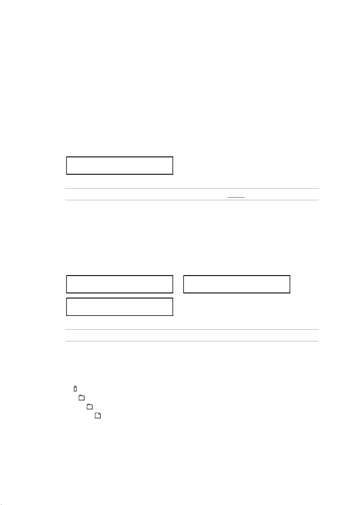
6.4 Setting Logos
2.LOGO SELECT
*NO DATA INT_1
2.IMPORT FROM USB
****.LG 1/**
DATA TRANSFER OK
■OK □CANCEL
IMPORT FROM USB
■■■■■■■■□□□□□□□ 50%
The logos (.lg format) that you create with the supplied Logo Application can be imported into
the LT 4600A and overlaid on SDI signals. Up to four logos can be imported. Imported logos
are retained even if the LT 4600A is restarted or initialized according to section 6.7,
“Initializing Settings.”
A logo can also be overlaid on an SDI signal without importing the logo, but in this case, the
logo is cleared when the LT 4600A is turned off.
Reference Section 10.8, “Setting Logos”
6.4.1 Selecting a Logo
To select a logo number, follow the procedure below. By factory default, all logo numbers
show NO DATA. If logos have been imported, their file names are displayed.
Procedure
UTILITY SETTING → LOGO DATA → LOGO SELECT → INT_1 - INT_4
6. LT 4600A CONFIGURATION (UTILITY SETTING)
6.4.2 Importing a Logo
To import a logo stored in a USB memory device to the number selected in section 6.4.1,
“Selecting a Logo,” follow the procedure below.
While the presets are being imported, an indicator appears to show the progress. When the
original screen returns, importing is finished. Do not turn the power off or remove the USB
memory device until the original screen returns.
Procedure
UTILITY SETTING → LOGO DATA → IMPORT FROM USB
● USB Memory Device File Structure
Place logos in the LOGO folder of the USB memory device. Up to 99 logos can be
selected from the LT 4600A. If a logo is already in the LT 4600A, it is overwritten.
USB memory device
LT4600A
└
└
└
LOGO
****.LG
27
Page 38
6.4.3 Exporting a Logo
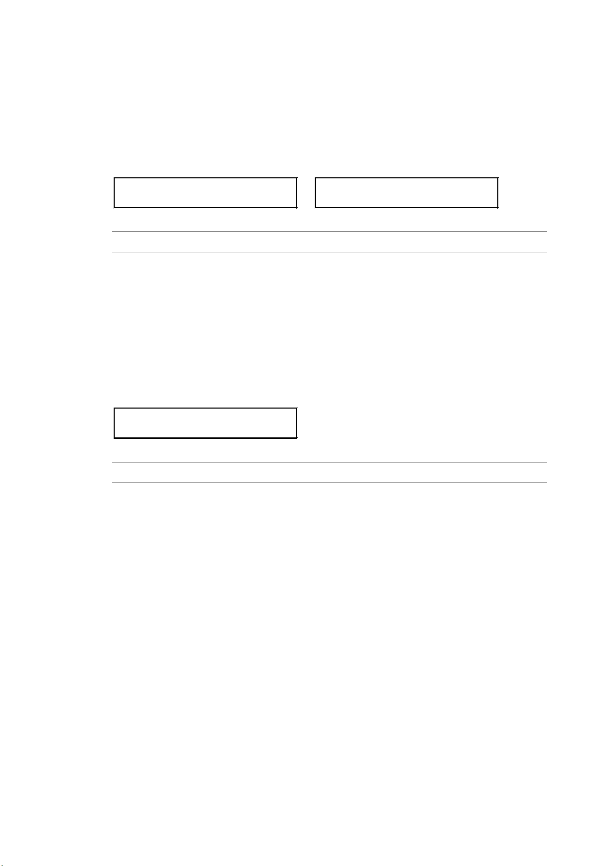
2.EXPORT TO USB
■OK □CANCEL
EXPORT TO USB
■■■■■■■■□□□□□□□ 50%
2.ERASE DATA
■OK □CANCEL
To export a logo selected in section 6.4.1, “Selecting a Logo,” to a USB memory device,
follow the procedure below.
While the presets are being exported, an indicator appears to show the progress. When the
original screen returns, exporting is finished. Do not turn the power off or remove the USB
memory device until the original screen returns.
Procedure
UTILITY SETTING → LOGO DATA → EXPORT TO USB
● USB Memory Device File Structure
Logos are exported to the LOGO folder in the USB memory device. (See section 6.4.2,
“Importing a Logo”) If a file with the same name already exists, it is overwritten.
The date and time of the exported file will be the date and time specified according to the
procedure in section 6.6, “Setting the Date and Time.”
6.4.4 Clearing a Logo
6. LT 4600A CONFIGURATION (UTILITY SETTING)
To clear a logo selected in section 6.4.1, “Selecting a Logo,” follow the procedure below.
Procedure
UTILITY SETTING → LOGO DATA → ERASE DATA
28
Page 39
6. LT 4600A CONFIGURATION (UTILITY SETTING)
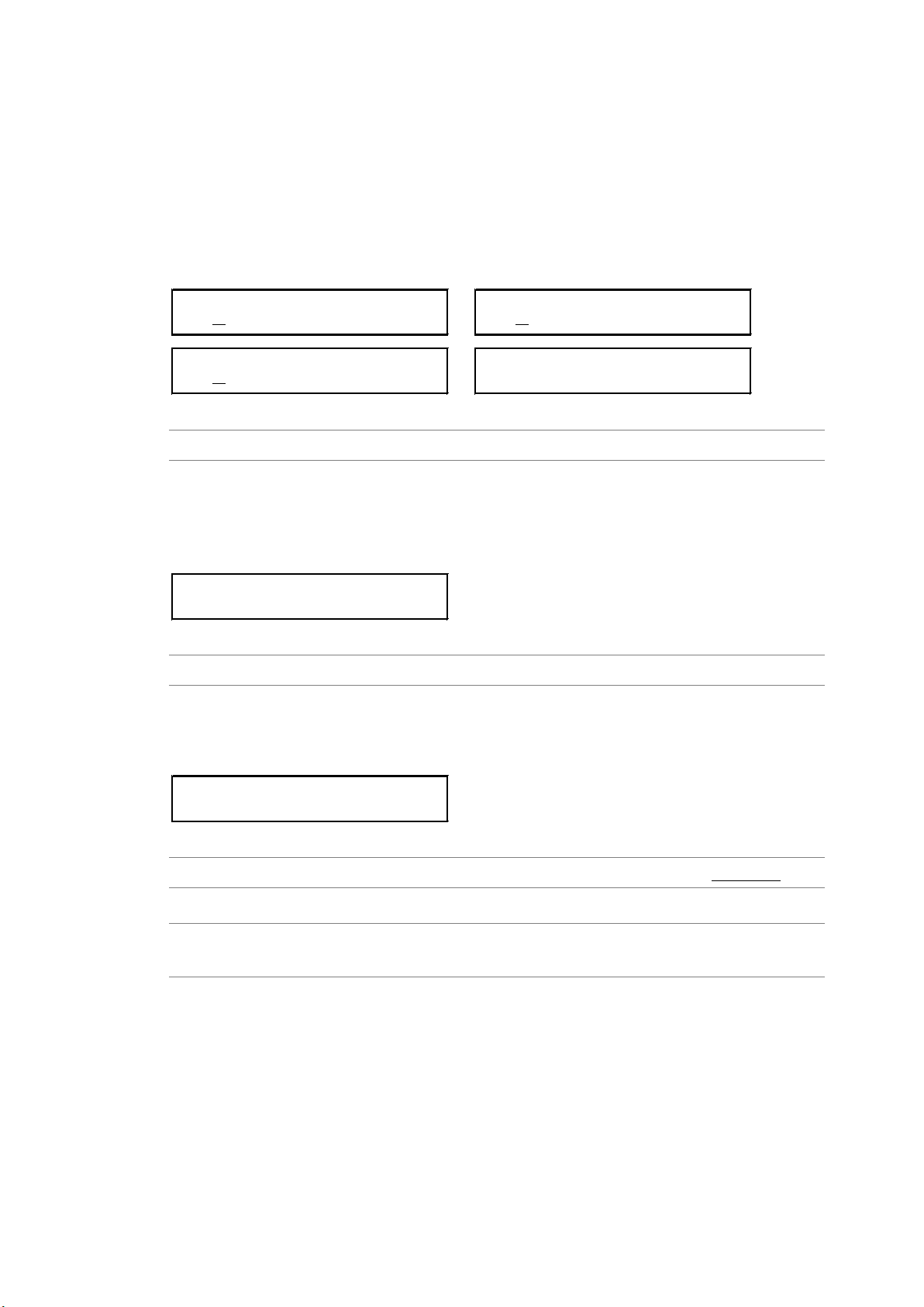
2.IP ADDRESS
192
.168.000.000
2.SUBNET MASK
255
.255.255.000
REBOOT ?
■OK □CANCEL
2.DEFAULT GATEWAY
000.000.000.000
2.MAC ADDRESS
**:**:**:**:**:**
3.ACTION
□ENABLE ■DISABLE
6.5 Configuring Ethernet Settings
6.5.1 Setting the IP Address
To set the IP address, subnet mask, and default gateway, follow the procedure below.
For the new IP address to take effect, you need to restart the LT 4600A. When you restart
the LT 4600A, some settings return to their factory default values. (See section 14.1, “List
of Settings.”)
If necessar y, save the current settings to a preset.
Procedure
UTILITY SETTING → ETHERNET → NETWORK SETTING
6.5.2 Viewing the MAC Address
To view the MAC address of the LT 4600A, follow the procedure below.
The MAC address is a unique number assigned to the device and cannot be changed.
Procedure
UTILITY SETTING → ETHERNET → MAC ADDRESS
6.5.3 Setting Trap Transmission
To select whether to transmit SNMP traps, follow the procedure below.
Procedure
UTILITY SETTING → ETHERNET → SNMP TRAP → ACTION: ENABLE / DISABLE
Settings
ENABLE: Traps are transmitted.
DISABLE: Traps are not transmitted.
29
Page 40
6. LT 4600A CONFIGURATION (UTILITY SETTING)
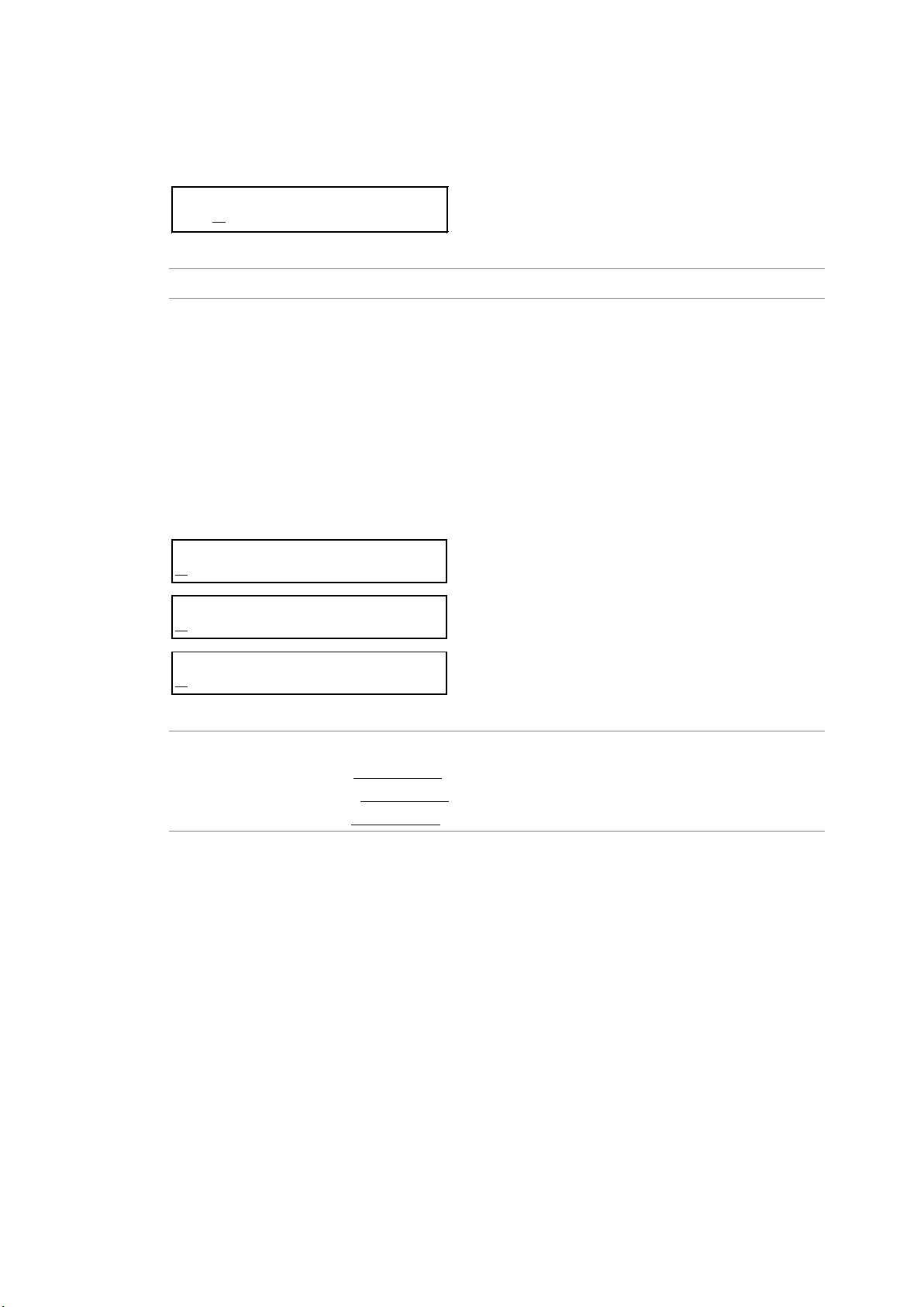
3.MANAGER IP
192
.168.000.000
3.READ COMMUNITY
L
DRUser
3.WRITE COMMUNITY
L
DRAdm
3.TRAP COMMUNITY
L
DRUser
6.5.4 Setting the Trap Transmission Destination
To set the IP address of the SNMP manager to send SNMP traps to, follow the procedure
below.
Procedure
UTILITY SETTING → ETHERNET → SNMP TRAP → MANAGER IP
6.5.5 Setting the Community Names
To change the SNMP read community, write community, and trap community, follow the
procedure below. To apply these settings, you need to restart the LT 4600A.
The characters that you can use are as follows. You can enter up to 15 characters.
0123456789ABCDEFGHIJKLMNOPQRSTUVWXYZabcdefghijklmnopqrstuvwxyz
▲
is the final character. If you enter this character, characters after this character will
▲
disappear, and you will not be able to edit them.
Procedure
UTILITY SETTING → ETHERNET → SNMP COMMUNITY
READ COMMUNITY: LDRUser
→
WRITE COMMUNITY: LDRAdm
→
TRAP COMMUNITY: LDRUser
→
▲
▲
▲
30
Page 41

6. LT 4600A CONFIGURATION (UTILITY SETTING)
2.GET MIB FILE
■OK □CANCEL
6.5.6 Retrieving the MIB File
To copy the MIB file, which is used for S N M P, from the LT 4600A to a USB memory device,
follow the procedure below.
Procedure
UTILITY SETTING → ETHERNET → GET MIB FILE
● USB Memory Device File Structure
The MIB file is saved in the MIB folder of the USB memory device. If a file already exists,
it is overwritten.
The date and time of the exported file will be the date and time specified according to the
procedure in section 6.6, “Setting the Date and Time.”
USB memory device
LT4600A
└
└
└
MIB
LT4600-MIB.mib
31
Page 42
6. LT 4600A CONFIGURATION (UTILITY SETTING)
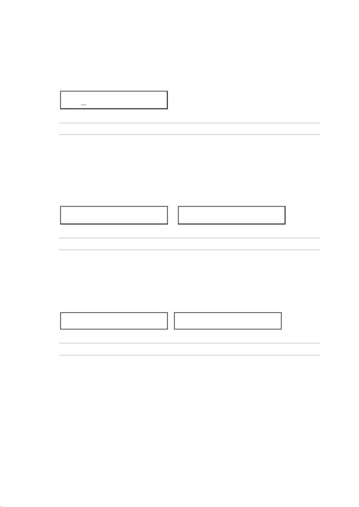
1.DATE & TIME ADJUST
201
2
/01/01 00:00:00
1.FACTORY DEFAULT
■OK □CANCEL
FORMAT & REBOOT OK ?
■OK □CANCEL
1.VERSION DISP(MAIN)
SYS :ver1.0
1.VERSION DISP(MAIN)
BOOT:ver1.0
6.6 Setting the Date and Time
To set the date and time, follow the procedure below.
The date and time are used in data exporting, genlock log, and so on.
The date and time are reset to their factory default values (2012/01/01 00:00:00) each time
the LT 4600A is started.
Procedure
UTILITY SETTING → DATE & TIME ADJUST
6.7 Initializing Settings
To reset all settings to their factory default values, follow the procedure below. For the factory
default values, see section 14.1, “List of Settings.” To initialize, you need to restart the LT
4600A.
Logos imported according to section 6.4.2, “Importing a Logo” are not deleted even if the LT
4600A is initialized.
Procedure
UTILITY SETTING → FACTORY DEFAULT
6.8 Viewing the Version Information
To view the LT 4600A version, follow the procedure below.
The LT 4600A version consists of a SYS version and BOOT version. SYS version is the main
version, and BOOT version is for maintenance. If you contact your local LEADER agent, tell
them the SYS version.
Procedure
UTILITY SETTING → VERSION DISPLAY
32
Page 43
7. GENLOCK FUNCTION (REFERENCE SETTING)
7. GENLOCK FUNCTION (REFERENCE SETTING)
7.1 Genlock Function
This chapter will explain how to use the LT 4600A for the following two lock modes.
Lock mode Reference signal Description
Internal mode Internal The internal reference signal is used.
Genlock mode External
7.1.1 Internal mode
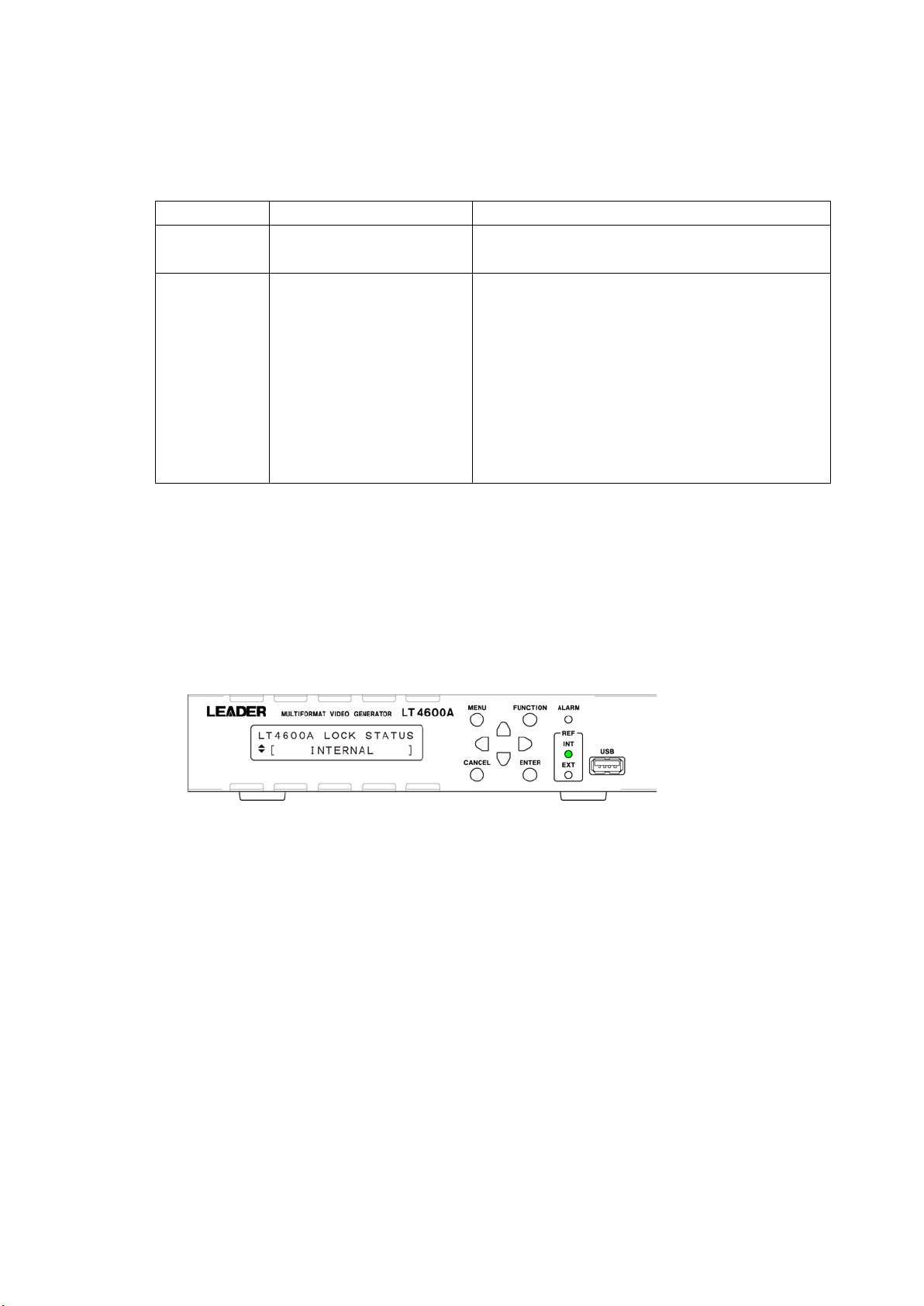
To switch to internal mode, under REFERENCE SETTING, set GENLOCK MODE to
INTERNAL.
Reference Section 7.2, “Selecting the Genlock Mode”
● Panel Display
(HD tri-level sync signal or
NTSC/PAL black burst signal)
The factory default setting is this mode.
An external reference signal received through
GENLOCK IN on the rear panel is used.
If the external reference signal is lost during operation,
the frequency immediately before the signal is lost is
maintained. (Stay-in-sync function)
During stay-in-sync operation, even if the external
reference signal returns, the LT 4600A will not lock back
on to the external reference signal until the LT 4600A is
instructed to do so from the front panel.
Under LT4600A LOCK STATUS, INTERNAL appears, and INT under REF lights in green.
33
Page 44
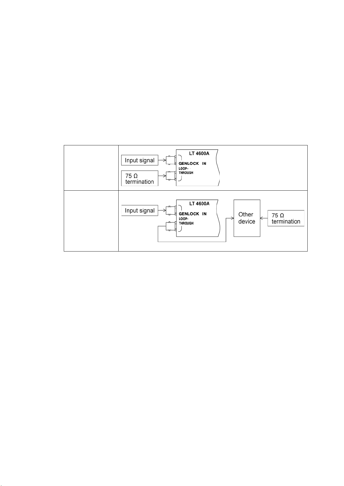
7.1.2 Genlock Mode
1. Under REFERENCE SETTING, set GENLOCK MODE to STAY-IN-SYNC.
7. GENLOCK FUNCTION (REFERENCE SETTING)
Reference Section 7.2, “Selecting the Genlock Mode”
2. Under REFERENCE SETTING, select LOCK FORMAT.
Select the reference signal format.
Reference Section 7.3, “Selecting the Genlock Format”
3. Apply a reference signal to GENLOCK IN on the rear panel.
The LT 4600A can use an HD tri-level sync or NTSC/PAL black burst signal for a
reference signal. Connect cables with a characteristic impedance of 75 Ω in one of the
following ways.
Input Method 1
Apply to one input
and terminate the
other at 75 Ω.
Input Method 2
Apply to one input
and connect the
other to another
device. Terminate
the device at the end
of the chain at 75 Ω.
34
Page 45
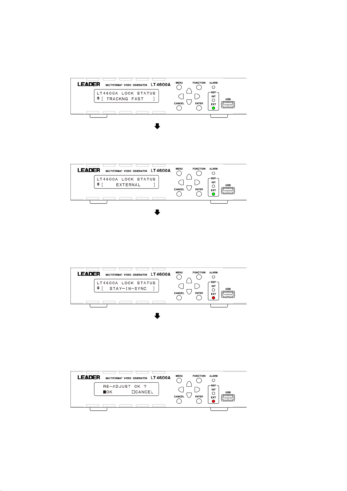
7. GENLOCK FUNCTION (REFERENCE SETTING)
● Panel Display
When you apply a reference signal, TRACKING FAST appears under LT4600A LOCK
STATUS, and EXT under REF blinks in green. This indicates that the reference signal is
being drawn in.
When genlock is complete, EXTERNAL appears under LT4600A LOCK STATU S, and
EXT under REF lights in green.
In genlock mode, use the LT 4600A in this condition.
If an error occurs in the external reference signal in the EXTERNAL state, the frequency
that was in use immediately before the error occurred is maintained (stay-in-sync
function).
Under LT4600A LOCK STATU S, STAY-IN-SYNC appears, and EXT under REF blinks in
red.
In the STAY-IN-SYNC status, even if the reference signal returns, the LT 4600A will not
automatically lock on to the reference signal. To lock on to the reference signal, set
GENLOCK MODE under REFERENCE SETTING to STAY-IN-SYNC, and then specify
RE-ADJUST.
Reference Section 7.2, “Selecting the Genlock Mode”
Relocking takes a few seconds, and the output signal becomes discontinuous.
35
Page 46
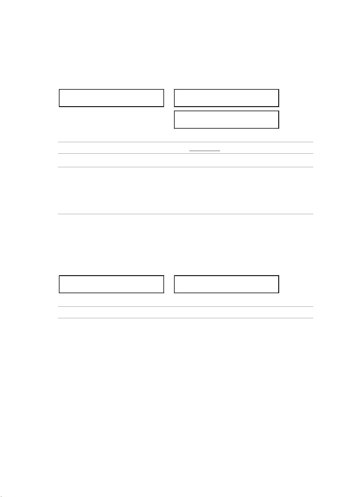
7. GENLOCK FUNCTION (REFERENCE SETTING)
RE-ADJUST OK ?
□OK ■CANCEL
1.GENLOCK MODE
*INTERNAL
CHANGE GL MODE ?
□OK ■CANCEL
1.LOCK FORMAT
*1125i/59.94
CHANGE GL FORMAT ?
■OK □CANCEL
7.2 Selecting the Genlock Mode
To select the genlock mode, follow the procedure below.
If you select STAY-IN-SYNC when the mode is already in STAY-IN-SYNC mode, a message
“RE-ADJUST OK?” will appear. This is used to relock when stay-in-sync operation is in
progress.
Procedure
REFERENCE SETTING → GENLOCK MODE: INTERNAL / STAY-IN-SYNC
Settings
INTERNAL: Internal mode is enabled. The internal reference signal is used.
STAY-IN-SYNC: Genlock mode is enabled. An external reference signal received through
GENLOCK IN on the rear panel is used. If the external reference signal is
lost during operation, the frequency immediately before the signal is lost is
maintained (stay-in-sync function).
7.3 Selecting the Genlock Format
To select the genlock format, follow the procedure below.
This setting is valid when GENLOCK MODE is set to STAY-IN-SYNC.
Note that the genlock formats are expressed in terms of the total number of lines, not the
number of effective lines.
Procedure
REFERENCE SETTING → LOCK FORMAT
● Genlock Formats
1125i/60, 1125i/59.94, 1125i/50,
1125p/30, 1125p/29.97, 1125p/25, 1125p/24, 1125p/23.98,
1125psF/24, 1125psF/23.98,
750p/60, 750p/59.94, 750p/50, 750p/30, 750p/29.97, 750p/25, 750p/24, 750p/23.98,
525i/59.94, NTSC BB (factory default value), NTSC BB+REF, NTSC BB+ID, NTSC
BB+REF+ID, 525p/59.94,
625i/50, PAL BB, PAL BB+REF, 625p/50
* REF represents the field reference pulse, and ID represents the field ID.
36
Page 47
7. GENLOCK FUNCTION (REFERENCE SETTING)
1.FINE PHASE ADJUST
0
1.GENLOCK LOG ON/OFF
□ON ■OFF
1.GENLOCK LOG DISP
00:2012/01/01 00:38
7.4 Adjusting the Timing (Fine Adjustment)
When the LT 4600A is locked in genlock mode, to finely adjust the black signal relative to the
reference signal, follow the procedure below.
The procedure here adjusts the timing of black signals 1 to 3 simultaneously. To adjust each
signal, see section 9.2, “Adjusting the Timing.”
The value takes effect immediately. Pressing CANCEL does not revert the setting to the
previous value.
Procedure
REFERENCE SETTING → FINE PHASE ADJUST: -20 - 0 - 20 (one step is approximately
0.5 ns)
7.5 Setting the Genlock Log
The genlock log records the changes in the genlock state and settings in chronological order.
Note that the log is cleared when the power is turned off.
7.5.1 Turning the Log On and Off
To set the genlock log to on or off, follow the procedure below.
This setting is not stored to presets.
Procedure
REFERENCE SETTING → GENLOCK LOG ON/OFF: ON / OFF
7.5.2 Viewing the Log
To view the genlock log, follow the procedure below.
Press
to view newer log entries, to view older log entries, and and to view the
details log entries.
You can view up to 100 entries from 00 to 99. Subsequent entries that occur overwrite the
oldest entries.
The date and time will be those specified according to the procedure in section 6.6, “Setting
the Date and Time.”
Procedure
REFERENCE SETTING → GENLOCK LOG DISP
37
Page 48

7.5.3 Saving the Log
1.GENLOCK LOG SAVE
■OK □CANCEL
To save the genlock log in log format to a USB memory device, follow the procedure below.
The content of a file in log format can be viewed using WordPad and other text editors.
Procedure
REFERENCE SETTING → GENLOCK LOG SAVE
● USB Memory Device File Structure
The genlock log is saved in the LOG folder in the USB memory device.
The date and time of the exported file will be the date and time specified according to the
procedure in section 6.6, “Setting the Date and Time.”
USB memory device
LT4600A
└
└
└
LOG
LT4600A_LOG_YYYYMMDDhhmmss.log
7. GENLOCK FUNCTION (REFERENCE SETTING)
38
Page 49
8. CONFIGURING THE SYSTEM (SYSTEM SETTING)
1.SYSTEM SELECT
*59.94Hz GROUP
CHANGE SYSTEM ?
■OK □CANCEL
2.MODE SELECT
*SDI 1 / 2
CHANGE MODE ?
■OK □CANCEL
8. CONFIGURING THE SYSTEM (SYSTEM SETTING)
SYSTEM SETTING is used to configure the LT 4600A operation.
Note that if you change the system settings, the settings specified using BLACK SETTING and
SDI SETTING are reset to their factory defaults.
8.1 Selecting the Frequency Group
To select the black-output and SDI-output frequency group, follow the procedure below.
When you change the frequency group, the settings specified using SDI OUTPUT SELECT
are reset to their factory defaults.
Procedure
SYSTEM SETTING → SYSTEM SELECT: 60.00Hz GROUP / 59.94Hz GROUP / 50.00Hz
GROUP
Settings
60.00Hz GROUP: 1080 or 720 images whose frame (field) frequency format is 60, 30, or
24 can be output.
59.94Hz GROUP: 1080 or 720 images whose frame (field) frequency format is 59.94,
29.97, or 23.98 can be output.
50.00Hz GROUP: 1080 or 720 images whose frame (field) frequency format is 50 or 25
can be output.
8.2 Selecting the SDI Output Mode
To select the SDI output mode, follow the procedure below.
Procedure
SYSTEM SETTING → SDI OUTPUT SELECT → MODE SELECT: SDI 1 / 2 / 3G-LvB / DUAL
Settings
SDI 1 / 2: 3G-A, HD, or SD is output. SDI OUT 1 and 2 can be set separately.
3G-LvB / DUAL: 3G-B or HD (DL) is output. When set to 3G-B, the same signal is output
from SDI OUT 1 and 2.
39
Page 50
8. CONFIGURING THE SYSTEM (SYSTEM SETTING)
2.SDI 1
*3G-SDI-LvA
OUTPUT CHANGE ?
■OK □CANCEL
2.SDI 2
*3G-SDI-LvA
OUTPUT CHANGE ?
■OK □CANCEL
2.3G-LvB/DUAL LINK
*3G-SDI-LvB
OUTPUT CHANGE ?
■OK □CANCEL
8.3 Selecting the SDI Output Signal
To select the SDI output mode, follow the procedure below.
Procedure
SYSTEM SETTING → SDI OUTPUT SELECT
→ SDI 1: 3G-SDI-LvA / HD/SD-SDI (when MODE SELECT is SDI 1 / 2)
→ SDI 2: 3G-SDI-LvA / HD/SD-SDI (when MODE SELECT is SDI 1 / 2)
→ 3G-LvB/DUAL LINK: 3G-SDI-LvB / HD DUAL LINK (when MODE SELECT is 3G-LvB /
DUAL)
Settings
3G-SDI-LvA: 3G-A is output from SDI OUT 1 or SDI OUT 2.
HD/SD-SDI: HD or SD is output from SDI OUT 1 or SDI OUT 2.
3G-SDI-LvB: 3G-B is output from SDI OUT 1 and SDI OUT 2.
HD DUAL LINK: HD (DL) is output from SDI OUT 1 and SDI OUT 2.
40
Page 51
9. ANALOG BLACK OUTPUT (BLACK SETTING)
2.BLK1 FORMAT
*1080i/59.94
CHANGE BLK1 FORMAT ?
■OK □CANCEL
9. ANALOG BLACK OUTPUT (BLACK SETTING)
Three analog black signals are output from the BLACK OUT connectors on the rear panel.
You can set the output signals using BLACK SETTING. Specify the settings under BLACK
SETTING after you have finished configuring the system settings. Note that if you change the
system settings, the settings specified using BLACK SETTING are reset to their factory
defaults.
Reference Chapter 8, “CONFIGURING THE SYSTEM (SYSTEM SETTING)”
In BLACK S E TTI N G, you can set the three signals separately. The procedure below is for black
1 (1A, 1B), but the same procedure can be applied to black 2 and 3.
9.1 Selecting the Black Format
To select the black signal format, follow the procedure below.
To use a normal composite black signal, select NTSC BB or PAL BB.
Procedure
BLACK SETTING → BLACK1 SIGNAL → BLK1 FORMAT
The formats that you can select vary depending on the frequency group that you selected in
section 8.1 “Selecting the Frequency Group,” as follows.
BLK* FORMAT
1080i/60 Yes No No
1080i/59.94 No Ye s No
1080i/50 No No Yes
1080p/30 Yes No No
1080p/29.97 No Ye s No
1080p/25 No No Ye s
1080p/24 Yes No No
1080p/23.98 No Ye s No
1080psF/24 Yes No No
1080psF/23.98 No Ye s No
720p/60 Yes No No
720p/59.94 No Ye s No
720p/50 No No Ye s
60.00Hz GROUP 59.94Hz GROUP 50.00Hz GROUP
SYSTEM SELECT
41
Page 52

9. ANALOG BLACK OUTPUT (BLACK SETTING)
BLK* FORMAT
720p/30 Yes No No
720p/29.97 No Ye s No
720p/25 No No Ye s
720p/24 Yes No No
720p/23.98 No Ye s No
NTSC BB FD FD FD
NTSC BB+REF Ye s Yes Yes
NTSC BB+ID Yes Yes Yes
NTSC BB+REF+ID Ye s Yes Yes
NTSC BB+SETUP Yes Yes Yes
NTSC BB+S+REF Yes Yes Yes
NTSC BB+S+ID Yes Yes Yes
NTSC BB+S+R+ID Yes Yes Yes
525i/59.94 Yes Yes Yes
525p/59.94 Yes Yes Yes
PAL BB Ye s Yes Yes
PAL BB+REF Yes Yes Yes
625i/50 Ye s Yes Yes
625p/50 Yes Ye s Yes
(Yes: Can be selected, No: Cannot be selected, FD: Factory default setting)
60.00Hz GROUP 59.94Hz GROUP 50.00Hz GROUP
SYSTEM SELECT
* R E F, R (Field REF): The following signal is included as a field ID signal.
• For NTSC, a 714 mV reference signal at line 10 (every two frames)
• For PA L, a 700 mV reference signal at line 7 (every four frames)
* ID (10 field ID): An ID signal complying with SMPTE ST 318 is included.
* SETUP, S (Setup): A 7.5IRE (7.5%) setup signal is included.
42
Page 53
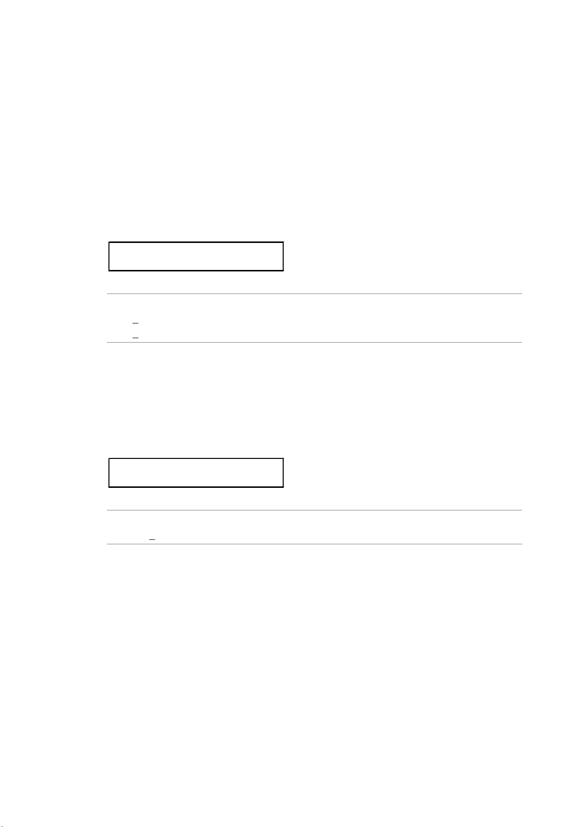
9. ANALOG BLACK OUTPUT (BLACK SETTING)
3.BLK1 F-PHASE
0 frame
3.BLK1 V-PHASE
0 line
9.2 Adjusting the Timing
Note that if you change the black format, the timing adjustment specified here is reset to its
factory default.
Reference Section 9.1, “Selecting the Black Format”
9.2.1 Adjusting the Timing (Frame)
To adjust the black signal relative to the reference signal at the frame level, follow the
procedure below.
This menu appears when BLK* FORMAT is set to NTSC *, 525i/59.94, PAL *, or 625i/50.
The value takes effect immediately. Pressing CANCEL does not revert the setting to the
previous value.
Procedure
BLACK SETTING → BLACK1 SIGNAL → BLK1 TIMING → BLK1 F-PHASE
: -5 - 0 - +5 (when BLK* FOR MAT is NTSC * or 525i/59.94)
: -2 - 0 - +2 (when BLK* FOR MAT is PAL * or 625i/50)
9.2.2 Adjusting the Timing (Line)
To adjust the black signal relative to the reference signal at the line level, follow the
procedure below. (The adjustment range provided below is the maximum. The range
depends on the format.)
The value takes effect immediately. Pressing CANCEL does not revert the setting to the
previous value.
Procedure
BLACK SETTING → BLACK1 SIGNAL → BLK1 TIMING → BLK1 V-PHASE
: -1124 - 0 - +1124
43
Page 54
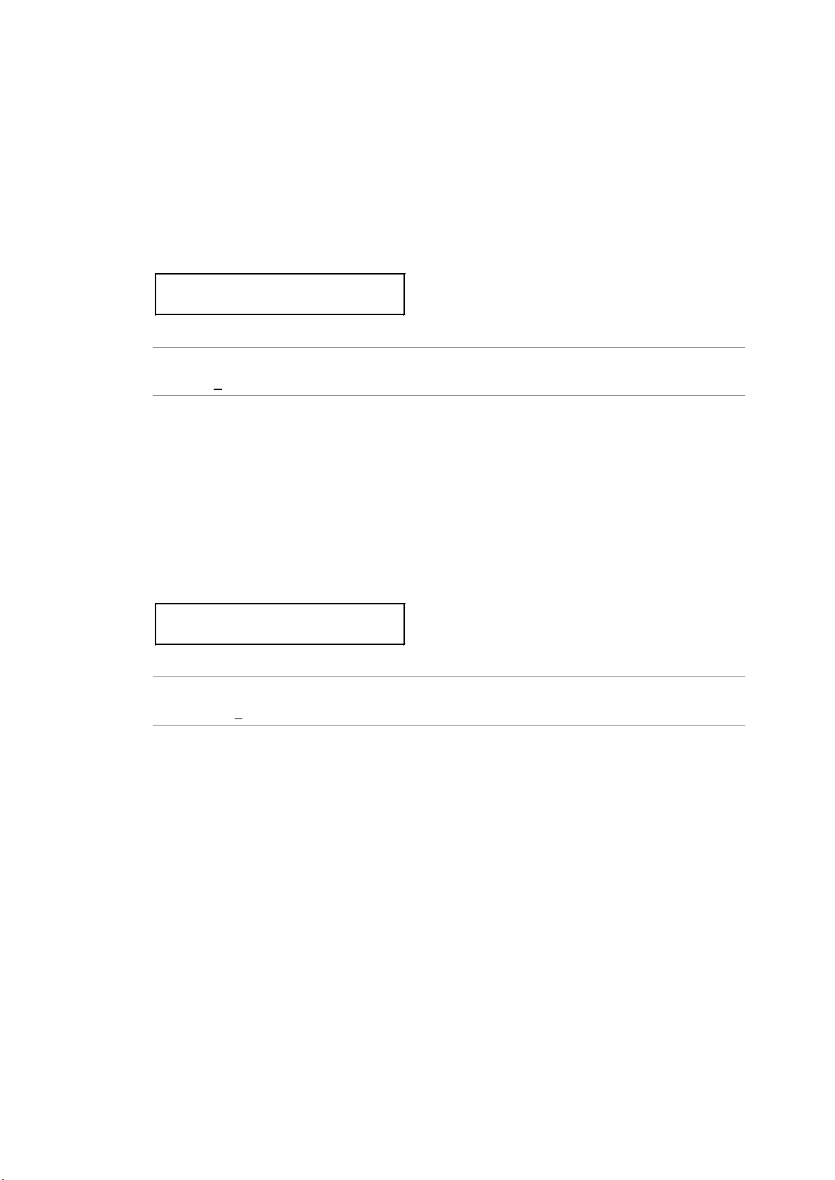
9. ANALOG BLACK OUTPUT (BLACK SETTING)
3.BLK1 H-PHASE[dot]
0 dot
3.BLK1 H-PHASE[μs]
+0.0000 μs
9.2.3 Adjusting the Timing (Dot)
To adjust the black signal relative to the reference signal at the dot level, follow the
procedure below. (The adjustment range provided below is the maximum. The range
depends on the format.)
You can also adjust at the time level instead of at the dot level. See section 9.2.4,
“Adjusting the Timing (Time).” Dot and time are mutually linked.
The value takes effect immediately. Pressing CANCEL does not revert the setting to the
previous value.
Procedure
BLACK SETTING → BLACK1 SIGNAL → BLK1 TIMING → BLK1 H-PHASE[dot]
: -4124 - 0 - +4124
9.2.4 Adjusting the Timing (Time)
To adjust the black signal relative to the reference signal at the time level, follow the
procedure below. (The adjustment range provided below is the maximum. The range
depends on the format.)
You can also adjust at the dot level instead of at the time level. See section 9.2.3,
“Adjusting the Timing (Dot).” Time and dot are mutually linked.
The value takes effect immediately. Pressing CANCEL does not revert the setting to the
previous value.
Procedure
BLACK SETTING → BLACK1 SIGNAL → BLK1 TIMING → BLK1 H-PHASE[μs]
: -63.9814 - 0 - +63.9814
44
Page 55
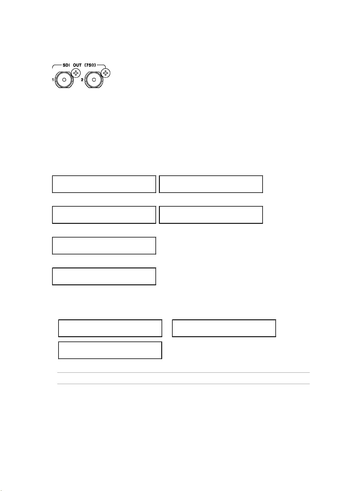
10. SDI OUTPUT (SDI SETTING)
0.SDI SETTING
SDI 1(3G-SDI-LvA)
0.SDI SETTING
SDI 2(3G-SDI-LvA)
0.SDI SETTING
SDI 1(HD/SD-SDI)
0.SDI SETTING
SDI 2(HD/SD-SDI)
0.SDI SETTING
SDI(3G-SDI-LvB)
0.SDI SETTING
SDI(HD DUAL LINK)
2.FORMAT
*422(YCbCr) 10bit
2.FORMAT
*1080p/59.94
CHANGE FORMAT ?
■OK □CANCEL
10. SDI OUTPUT (SDI SETTING)
Two SDI signals are output from the SDI OUT connectors on the rear panel.
You can set the output signals using SDI SE T T I N G. Specify the settings under SDI SETTING
after you have finished configuring the system settings. Note that if you change the system
settings, the settings specified using SDI SETTING are reset to their factory defaults.
Reference Chapter 8, “CONFIGURING THE SYSTEM (SYSTEM SETTING)”
The settings under SDI SETTING vary depending on the signal selected in section 8.3,
“Selecting the SDI Output Signal,” as shown below, but the procedure explanations use the
term “SDI” to cover all these cases.
When SDI 1 or SDI 2 is 3G-SDI-LvA
When SDI 1 or SDI 2 is HD/SD-SDI
When SDI is 3G-SDI-LvB
When SDI is HD DUAL LINK
10.1 Selecting the SDI Format
To select the SDI signal format and color system, follow the procedure below.
Procedure
SDI SETTING → SDI → FOR MAT
45
Page 56

10. SDI OUTPUT (SDI SETTING)
The selectable format and color system combinations are shown below.
Formats not listed cannot be selected. In addition, the formats that you can select vary
depending on the frequency group that you selected in section 8.1 “Selecting the Frequency
Group.”
● 3G-A Output
Color System
Format
1080i/60 No Yes Yes Ye s Yes Yes 60.00Hz
1080i/59.94 No Yes Ye s Yes Ye s Ye s 59.94Hz
1080i/50 No Ye s Yes Ye s Yes Ye s 50.00Hz
1080p/60 Yes No No No No No 60.00Hz
1080p/59.94 FD No No No No No 59.94Hz
1080p/50 Yes No No No No No 50.00Hz
1080p/30 No Ye s Ye s Yes Ye s Ye s 60.00Hz
1080p/29.97 No Ye s Yes Ye s Yes Yes 59.94Hz
1080p/25 No Ye s Ye s Yes Ye s Ye s 50.00Hz
1080p/24 No Ye s Ye s Yes Ye s Ye s 60.00Hz
1080p/23.98 No Ye s Yes Ye s Yes Yes 59.94Hz
1080psF/30 No Ye s Yes No Yes No 60.00Hz
1080psF/29.97 No Ye s Ye s No Yes No 59.94Hz
1080psF/25 No Ye s Yes No Yes No 50.00Hz
1080psF/24 No Ye s Yes No Yes No 60.00Hz
1080psF/23.98 No Ye s Ye s No Yes No 59.94Hz
720p/60 No No Yes No Yes No 60.00Hz
720p/59.94 No No Ye s No Yes No 59.94Hz
720p/50 No No Yes No Yes No 50.00Hz
720p/30 No No Yes No Yes No 60.00Hz
720p/29.97 No No Ye s No Yes No 59.94Hz
720p/25 No No Yes No Yes No 50.00Hz
720p/24 No No Yes No Yes No 60.00Hz
720p/23.98 No No Ye s No Yes No 59.94Hz
(Yes: Can be selected, No: Cannot be selected, FD: Factory default setting)
422(YCbCr)
10 bits
422(YCbCr)
12 bits
444(YCbCr)
10 bits
444(YCbCr)
12 bits
444(RGB)
10 bits
444(RGB)
12 bits
SYSTEM
SELECT
46
Page 57
● 3G-B Output
10. SDI OUTPUT (SDI SETTING)
Color System
Format
1080i/60 No Ye s Yes Ye s Yes Ye s 60.00Hz
1080i/59.94 No Yes Ye s Yes Ye s Ye s 59.94Hz
1080i/50 No Ye s Yes Ye s Yes Ye s 50.00Hz
1080p/60 Yes No No No No No 60.00Hz
1080p/59.94 FD No No No No No 59.94Hz
1080p/50 Yes No No No No No 50.00Hz
1080p/30 No Ye s Ye s Yes Ye s Ye s 60.00Hz
1080p/29.97 No Ye s Yes Ye s Yes Yes 59.94Hz
1080p/25 No Ye s Ye s Yes Ye s Ye s 50.00Hz
1080p/24 No Ye s Ye s Yes Ye s Ye s 60.00Hz
1080p/23.98 No Ye s Yes Ye s Yes Yes 59.94Hz
1080psF/30 No Ye s Yes No Yes No 60.00Hz
1080psF/29.97 No Ye s Ye s No Yes No 59.94Hz
1080psF/25 No Ye s Yes No Yes No 50.00Hz
1080psF/24 No Ye s Yes No Yes No 60.00Hz
1080psF/23.98 No Ye s Ye s No Yes No 59.94Hz
(Yes: Can be selected, No: Cannot be selected, FD: Factory default setting)
422(YCbCr)
10 bits
422(YCbCr)
12 bits
444(YCbCr)
10 bits
444(YCbCr)
12 bits
444(RGB)
10 bits
444(RGB)
12 bits
● HD (DL) Output
SYSTEM
SELECT
Color System
Format
1080i/60 No Ye s Yes Ye s Yes Ye s 60.00Hz
1080i/59.94 No Yes Ye s Yes Ye s Ye s 59.94Hz
1080i/50 No Ye s Yes Ye s Yes Ye s 50.00Hz
1080p/60 Yes No No No No No 60.00Hz
1080p/59.94 FD No No No No No 59.94Hz
1080p/50 Yes No No No No No 50.00Hz
1080p/30 No Ye s Ye s Yes Ye s Ye s 60.00Hz
1080p/29.97 No Ye s Yes Ye s Yes Yes 59.94Hz
1080p/25 No Ye s Ye s Yes Ye s Ye s 50.00Hz
1080p/24 No Ye s Ye s Yes Ye s Ye s 60.00Hz
1080p/23.98 No Ye s Yes Ye s Yes Yes 59.94Hz
1080psF/30 No Ye s Yes Yes Ye s Ye s 60.00Hz
1080psF/29.97 No Ye s Ye s Yes Ye s Ye s 59.94Hz
1080psF/25 No Ye s Yes Yes Ye s Ye s 50.00Hz
1080psF/24 No Ye s Yes Yes Ye s Ye s 60.00Hz
1080psF/23.98 No Ye s Ye s Yes Ye s Ye s 59.94Hz
(Yes: Can be selected, No: Cannot be selected, FD: Factory default setting)
422(YCbCr)
10 bits
422(YCbCr)
12 bits
444(YCbCr)
10 bits
444(YCbCr)
12 bits
444(RGB)
10 bits
444(RGB)
12 bits
SYSTEM
SELECT
47
Page 58
● HD/SD Output
3.PATTERN SELECT
*COLOR BAR 100%
10. SDI OUTPUT (SDI SETTING)
Color System
Format
1080i/60 Yes No No No No No 60.00Hz
1080i/59.94 FD No No No No No 59.94Hz
1080i/50 Yes No No No No No 50.00Hz
1080p/30 Yes No No No No No 60.00Hz
1080p/29.97 Ye s No No No No No 59.94Hz
1080p/25 Yes No No No No No 50.00Hz
1080p/24 Yes No No No No No 60.00Hz
1080p/23.98 Ye s No No No No No 59.94Hz
1080psF/24 Ye s No No No No No 60.00Hz
1080psF/23.98 Ye s No No No No No 59.94Hz
720p/60 Ye s No No No No No 60.00Hz
720p/59.94 Ye s No No No No No 59.94Hz
720p/50 Ye s No No No No No 50.00Hz
720p/30 Ye s No No No No No 60.00Hz
720p/29.97 Ye s No No No No No 59.94Hz
720p/25 Ye s No No No No No 50.00Hz
720p/24 Ye s No No No No No 60.00Hz
720p/23.98 Ye s No No No No No 59.94Hz
525i/59.94 Ye s No No No No No -
625i/50 Yes No No No No No -
(Yes: Can be selected, No: Cannot be selected, FD: Factory default setting)
422(YCbCr)
10 bits
422(YCbCr)
12 bits
444(YCbCr)
10 bits
444(YCbCr)
12 bits
444(RGB)
10 bits
444(RGB)
12 bits
10.2 Configuring Patterns
SYSTEM
SELECT
10.2.1 Selecting the Pattern
To select the output pattern, follow the procedure below.
Procedure
SDI SETTING → SDI → PATTERN → PATTERN SELECT: COLOR BAR 100% /
COLOR BAR 75% / MULTI CB 100% / MULT I CB 75% / MULT I CB (+I) /
SMPTE COLOR BAR / EBU COLOR BAR / BBC COLOR BAR / CHECK FIELD /
BLUE FIELD 100% / GREEN FIELD 100% / RED FIELD 100% /
FLAT FIELD 0% / FLAT FIELD 100%
48
Page 59
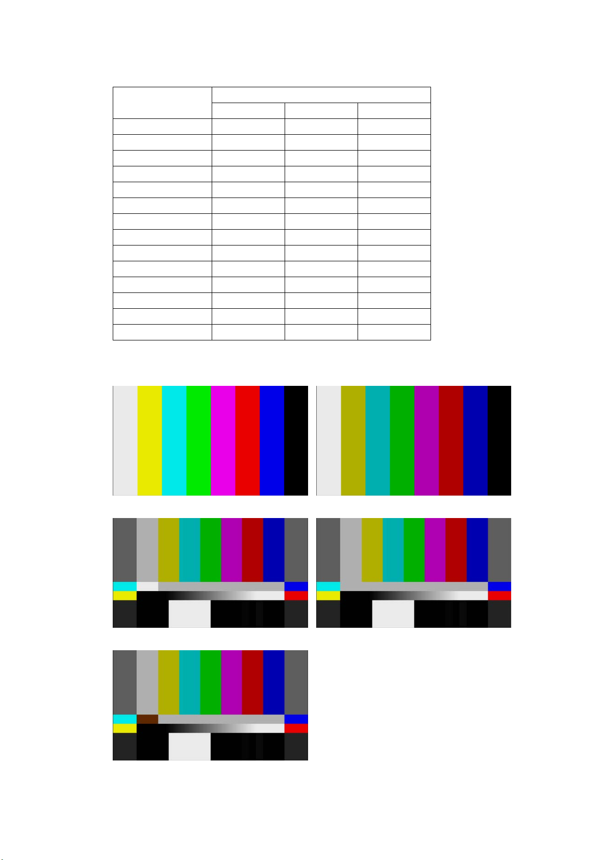
10. SDI OUTPUT (SDI SETTING)
The selectable patterns depend on the output format as shown below.
Pattern
COLOR BAR 100% Ye s Ye s Yes
COLOR BAR 75% Yes Ye s No
MULTI CB 100% Yes No No
MULTI CB 75% Yes No No
MULTI CB (+I) Yes No No
SMPTE COLOR BAR No Yes No
EBU COLOR BAR No No Ye s
BBC COLOR BAR No No Ye s
CHECK FIELD Ye s Ye s Yes
BLUE FIELD 100% Yes Ye s Yes
GREEN FIELD 100% Ye s Ye s Ye s
RED FIELD 100% Ye s Ye s Ye s
FLAT FIELD 0% Yes Ye s Yes
FLAT FIELD 100% Yes Ye s Ye s
(Yes: Can be selected No: Cannot be selected)
3G/HD(DL)/HD 525i/59.94 625i/50
Format
COLOR BAR 100% COLOR BAR 75%
MULTI CB 100% MULTI CB 75%
MULTI CB (+I)
49
Page 60

10. SDI OUTPUT (SDI SETTING)
SMPTE COLOR BAR EBU COLOR BAR
BBC COLOR BAR CHECK FIELD
BLUE FIELD 100% GREEN FILED 100%
RED FIELD 100%
50
Page 61
10. SDI OUTPUT (SDI SETTING)
4.SCROLL ON/OFF
□ON ■OFF
5.DIRECTION
*UP & RIGHT
FLAT FIELD 0% FLAT FIELD 100%
10.2.2 Turning Pattern Scrolling On and Off
To turn pattern scrolling on and off, follow the procedure shown below.
If the check field pattern is selected, the patter will not scroll even if this is set to ON.
Procedure
SDI SETTING → SDI → PATTERN → PATTE RN SCROLL → SCROLL ON/OFF: ON / OFF
10.2.3 Setting the Pattern Scroll Direction
To select the pattern scroll direction, follow the procedure below.
Procedure
SDI SETTING → SDI → PATTERN → PATTERN SCROLL → SCROLL PARAM SET →
DIRECTION: UP & RIGHT / UP / UP & LEFT / LEFT / DOWN & LEFT / DOWN / DOWN &
RIGHT / RIGHT
51
Page 62
10. SDI OUTPUT (SDI SETTING)
5.H SPEED
0 dot
5.V SPEED
0 dot
4.CHANGE ON/OFF
□ON ■OFF
4.SPEED
+1 sec
10.2.4 Setting the Pattern Scroll Speed
To select the pattern scroll speed, follow the procedure below.
The unit is dot/field (frame). If the speed is set to 0, the pattern will not scroll.
The value takes effect immediately. Pressing CANCEL does not revert the setting to the
previous value.
Procedure
SDI SETTING → SDI → PATTERN → PATTERN SCROLL → SCROLL PARAM SET
→ H SPEED: 0 - +256 (horizontal direction, 2 dot steps)
→ V SPEED: 0 - +256 (vertical direction, 1 dot steps)
10.2.5 Turning Pattern Change On and Off
To turn pattern change on and off, follow the procedure shown below.
If set to ON, the pattern is switched automatically between the available patterns (except
for the check field) in the current format.
Procedure
SDI SETTING → SDI → PATTERN → PATTERN CHANGE → CHANGE ON/OFF: ON /
OFF
10.2.6 Setting the Pattern Change Speed
To select the pattern change interval, follow the procedure below.
Procedure
SDI SETTING → SDI → PATTERN → PATTERN CHANGE → SPEED: +1 - +255
52
Page 63
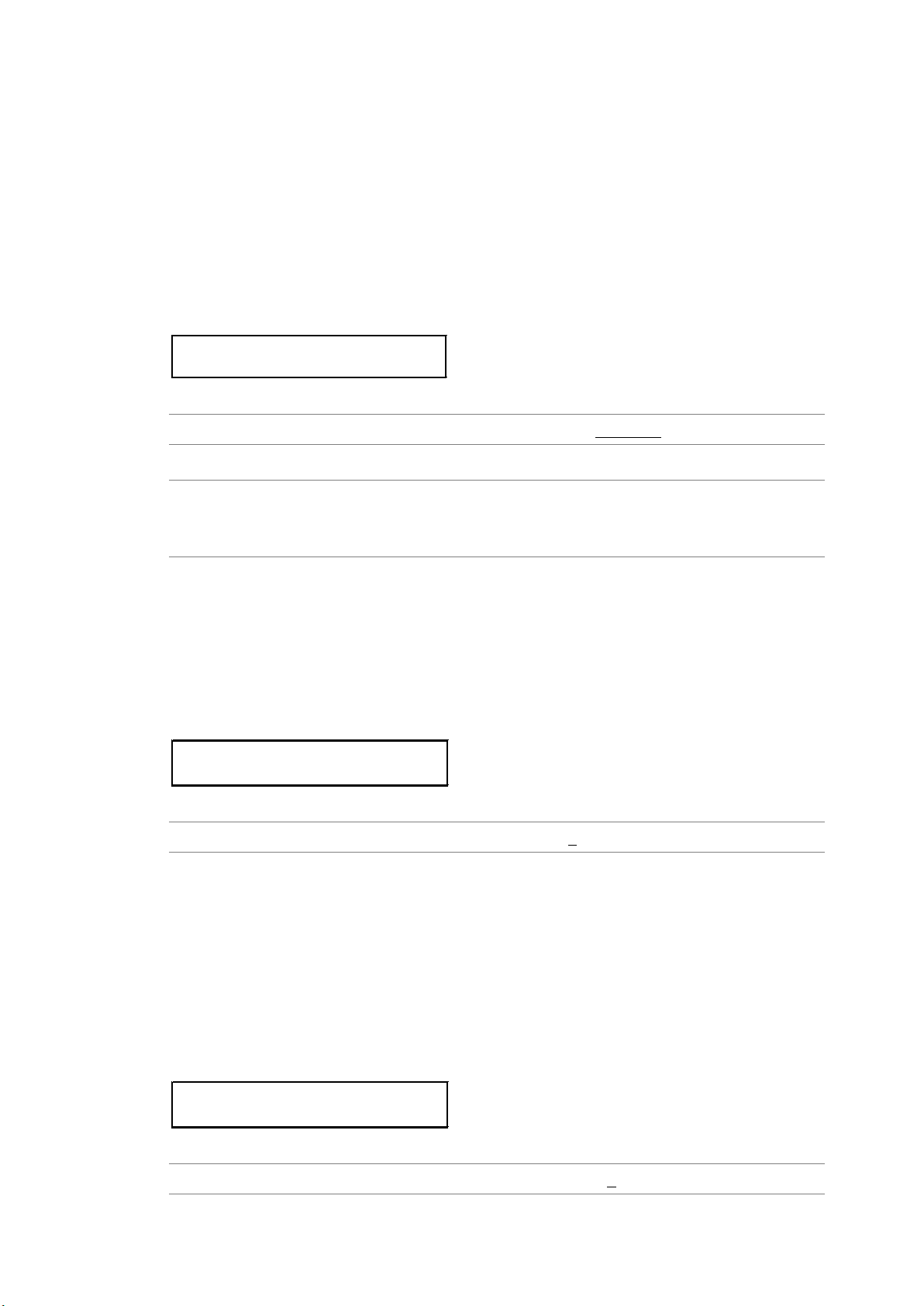
10. SDI OUTPUT (SDI SETTING)
3.0H TIMING
□SERIAL ■LEGACY
3.V-PHASE
0 line
3.H-PHASE [dot]
0 dot
10.3 Adjusting the Timing
Note that if you change the SDI format, the timing adjustment specified here is reset to its
factory default.
Reference Section 10.1, “Selecting the SDI Format”
10.3.1 Selecting the Timing Reference
To select the output timing used as a reference for the SDI and black signals, follow the
procedure below.
When the output signal is 3G, this menu item is not displayed. If is fixed at SERIAL.
Procedure
SDI SETTING → SDI → TIMING → 0H TIMING: SERIAL / LEGACY
Settings
SERIAL: Signals are output at the timing defined in the signal standard.
LEGACY: Signals are output at the same timing as LEADER’s conventional signal
generators.
10.3.2 Adjusting the Timing (Line)
To adjust the SDI signal relative to the reference signal at the line level, follow the
procedure below. (The adjustment range provided below is the maximum. The range
depends on the format.)
The value takes effect immediately. Pressing CANCEL does not revert the setting to the
previous value.
Procedure
SDI SETTING → SDI → TIMING → V-PHASE: -1124 - 0 - +1124
10.3.3 Adjusting the Timing (Dot)
To adjust the SDI signal relative to the reference signal at the dot level, follow the
procedure below. (The adjustment range provided below is the maximum. The range
depends on the format.)
You can also adjust at the time level instead of at the dot level. See section 10.3.4,
“Adjusting the Timing (Time).” Dot and time are mutually linked.
The value takes effect immediately. Pressing CANCEL does not revert the setting to the
previous value.
Procedure
SDI SETTING → SDI → TIMING → H-PHASE [dot]: -4124 - 0 - +4124
53
Page 64
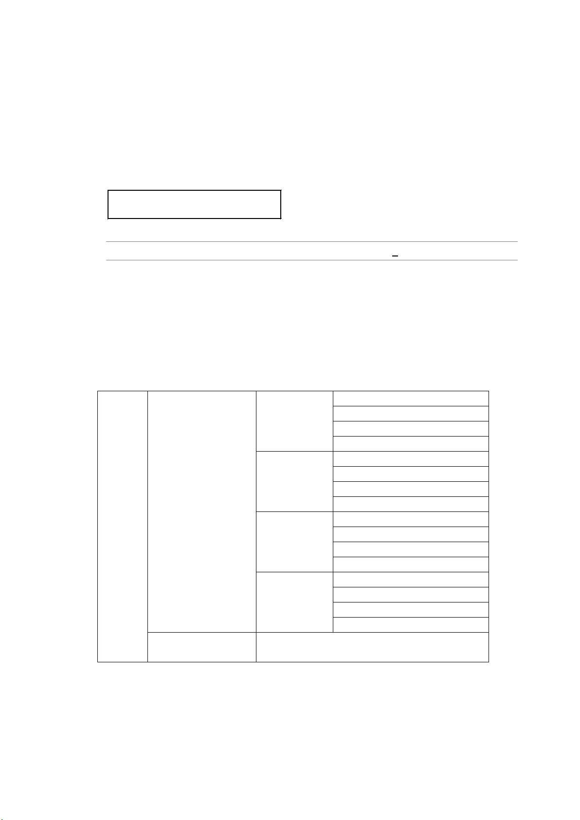
10. SDI OUTPUT (SDI SETTING)
3.H-PHASE [μs]
+0.0000 μsec
10.3.4 Adjusting the Timing (Time)
To adjust the SDI signal relative to the reference signal at the time level, follow the
procedure below. (The adjustment range provided below is the maximum. The range
depends on the format.)
You can also adjust at the dot level instead of at the time level. See section 10.3.3,
“Adjusting the Timing (Dot).” Time and dot are mutually linked.
The value takes effect immediately. Pressing CANCEL does not revert the setting to the
previous value.
Procedure
SDI SETTING → SDI → TIMING → H-PHASE [μs]: -63.9629 - 0 - +63.9629
10.4 Configuring Embedded Audio
16 audio channels (32 channels for 3G-B) can be embedded in an SDI signal.
Channels 1 to 4, 5 to 8, 9 to 12, and 13 to 16 are called group 1, 2, 3, and 4, respectively. The
frequency, level, and the like can be set for each channel separately.
In addition, if you link the group 2 settings to the group 1 settings, you only need to set group
1, and the group 2 settings will automatically be set to the same values as group 1.
Ch1
Ch2 (can also be set equal to Ch1)
Ch3 (can also be set equal to Ch1)
Ch4 (can also be set equal to Ch1)
Ch5
Ch6 (can also be set equal to Ch5)
Ch7 (can also be set equal to Ch5)
Ch8 (can also be set equal to Ch5)
Ch9
Ch10 (can also be set equal to Ch9)
Ch 11 (can also be set equal to Ch9)
Ch12 (can also be set equal to Ch9)
Ch13
Ch14 (can also be set equal to Ch13)
Ch15 (can also be set equal to Ch13)
Ch16 (can also be set equal to Ch13)
SDI signal
Link A (3G-B only)
Link B (3G-B only)
(can also be set to link A)
Group 1
Group 2
(can also be set
equal to group 1)
Group 3
Group 4
(can also be set
equal to group 3)
Same as link A
54
Page 65
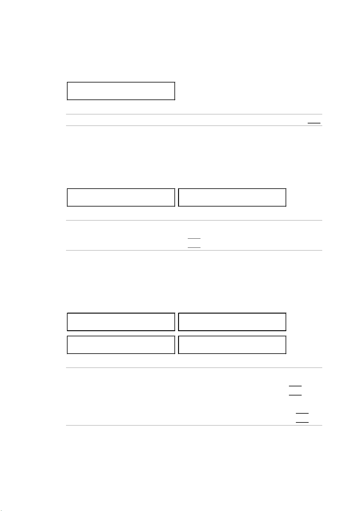
10. SDI OUTPUT (SDI SETTING)
4.EQUAL TO LINK-A
□ON ■OFF
5.EQUAL TO G1
□ON ■OFF
5.EQUAL TO G3
□ON ■OFF
7.EQUAL TO CH1
□ON ■OFF
7.EQUAL TO CH5
□ON ■OFF
7.EQUAL TO CH9
□ON ■OFF
7.EQUAL TO CH13
□ON ■OFF
10.4.1 Settings Shared by Links
If the output signal is 3G-B, the link B settings can be linked to link A settings by following
the procedure below to select ON. It is possible to set the link B settings even when this is
set to ON, but the values will be ignored.
Procedure
SDI SETTING → SDI → EMBEDDED AUDIO → LINK-B → EQUAL TO LINK-A: ON / OFF
10.4.2 Settings Shared by Groups
You can link the group 2 settings to the group 1 settings by following the procedure below
to set EQUAL TO G1 to ON. It is possible to set the group B settings even when this is set
to ON, but the values will be ignored.
The same hold true for EQUAL TO G3.
Procedure
SDI SETTING → SDI → EMBEDDED AUDIO
→ GROUP 2 SET → EQUAL TO G1: ON / OFF
→ GROUP 4 SET → EQUAL TO G3: ON / OFF
10.4.3 Settings Shared by Channels
You can link the channel 2 setting to the channel 1 setting by following the procedure below
to set EQUAL TO CH1 to ON. It is possible to set the channel 2 setting even when this is
set to ON, but the value will be ignored.
The same holds true for the other similar settings.
Procedure
SDI SETTING → SDI → EMBEDDED AUDIO
→ GROUP 1 SET → CH SELECT → GROUP1 CH2 → EQUAL TO CH1: ON / OFF
→ GROUP 1 SET → CH SELECT → GROUP1 CH3 → EQUAL TO CH1: ON / OFF
(Omitted)
→ GROUP 4 SET → CH SELECT → GROUP1 CH15 → EQUAL TO CH13: ON / OFF
→ GROUP 4 SET → CH SELECT → GROUP1 CH16 → EQUAL TO CH13: ON / OFF
55
Page 66
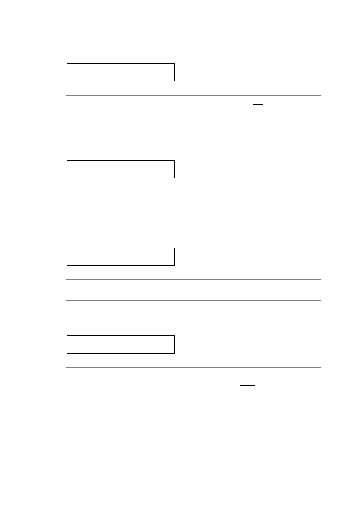
10. SDI OUTPUT (SDI SETTING)
4.AUDIO ON/OFF
*■G1 ■G2 ■G3 ■G4
5.RESOLUTION
■20bit □24bit
5.EMPHASIS
□50/15 □CCITT ■OFF
7.FREQUENCY
*1kHz
10.4.4 Turning the Audio On and Off
To turn the audio on or off at the group level, follow the procedure below.
Procedure
SDI SETTING → SDI → EMBEDDED AUDIO → AUDIO ON/OFF: ON / OFF
10.4.5 Selecting the Resolution
To select the resolution for the selected group, follow the procedure below.
If the output signal is 525i/59.94, not all groups can be set to 24 bit. Up to three groups can
be set to 24 bit.
Procedure
SDI SETTING → SDI → EMBEDDED AUDIO → GROUP * SET → RESOLUTION: 20bit /
24bit
10.4.6 Selecting the Pre-emphasis Mode
To select the pre-emphasis mode for the selected group, follow the procedure below.
Procedure
SDI SETTING → SDI → EMBEDDED AUDIO → GROUP * SET → EMPHASIS: 50/15 /
CCITT / OFF
10.4.7 Selecting the Frequency
To select the frequency of the selected channel, follow the procedure below.
Procedure
SDI SETTING → SDI → EMBEDDED AUDIO → GROUP * SET → CH SELECT →
GROUP * CH* → FREQUENCY: SILENCE / 400Hz / 800Hz / 1kHz
56
Page 67

10.4.8 Setting the Level
7.LEVEL
-20 dBFS
7.CLICK
*OFF ↵
2.Y,Cb,Cr ON/OFF
*■G/Y ■B/Cb ■R/Cr
3.90% AREA
□ON ■OFF
10. SDI OUTPUT (SDI SETTING)
To set the level of the selected channel, follow the procedure below.
Procedure
SDI SETTING → SDI → EMBEDDED AUDIO → GROUP * SET → CH SELECT →
GROUP * CH* → LEVEL: -60 - -20 - 0
10.4.9 Setting Clicks
You can insert click sounds into the selected channel. Follow the procedure below to set
the insertion interval in the range of 1 sec to 4 sec.
This setting is valid when LIPSYNC is set to OFF.
Procedure
SDI SETTING → SDI → EMBEDDED AUDIO → GROUP * SET → CH SELECT →
GROUP * CH* → CLICK: OFF / 1sec / 2sec / 3sec / 4sec
10.5 Turning YCbCr On and Off
To turn individual components in a YCbCr or GBR signal on and off, follow the procedure
below.
Procedure
SDI SETTING → SDI → Y,Cb,Cr ON/OFF: ON / OFF
10.6 Configuring Marker Settings
10.6.1 Turning the 90% Marker On and Off
To turn the 90% marker on and off, follow the procedure below.
If the 4:3 marker is off, the 90% marker is displayed at the outer frame of the picture. If the
4:3 marker is on, the marker is displayed at the 90% position by assuming the 4:3 marker
to be 100%.
Procedure
SDI SETTING → SDI → SAFETY AREA → 90% AREA: ON / OFF
57
Page 68
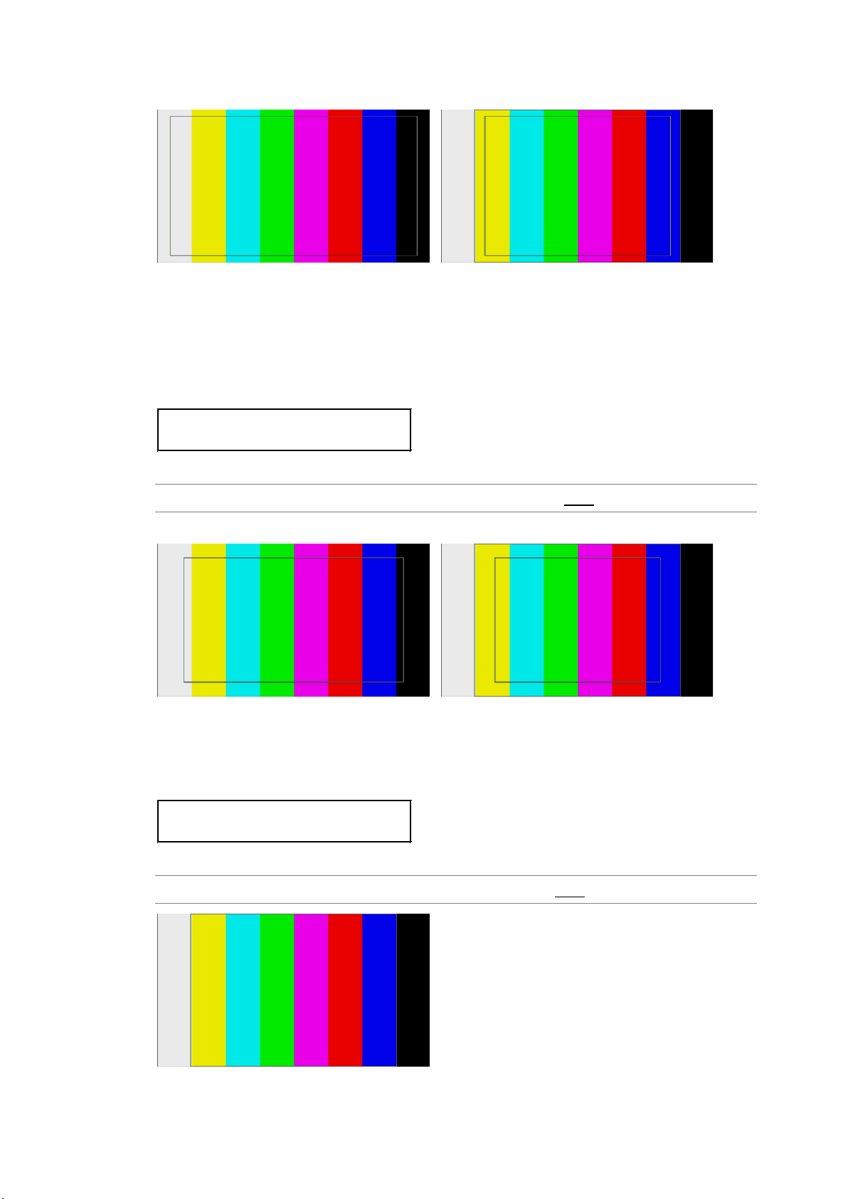
10. SDI OUTPUT (SDI SETTING)
3.80% AREA
□ON ■OFF
3.4:3 AREA
□ON ■OFF
90% AREA = ON / 4:3 AREA = OFF 90% AREA = ON / 4:3 AREA = ON
10.6.2 Turning the 80% Marker On and Off
To turn the 80% marker on and off, follow the procedure below.
If the 4:3 marker is off, the 80% marker is displayed at the outer frame of the picture. If the
4:3 marker is on, the marker is displayed at the 90% position by assuming the 4:3 marker
to be 100%.
Procedure
SDI SETTING → SDI → SAFETY AREA → 80% AREA: ON / OFF
80% AREA = ON / 4:3 AREA = OFF 80% AREA = ON / 4:3 AREA = ON
10.6.3 Turning the 4:3 Marker On and Off
To turn the 4:3 marker on and off, follow the procedure below.
This menu item does not appear if the output format is 525i/59.94 or 625i/50.
Procedure
SDI SETTING → SDI → SAFETY AREA → 4:3 AREA: ON / OFF
58
Page 69
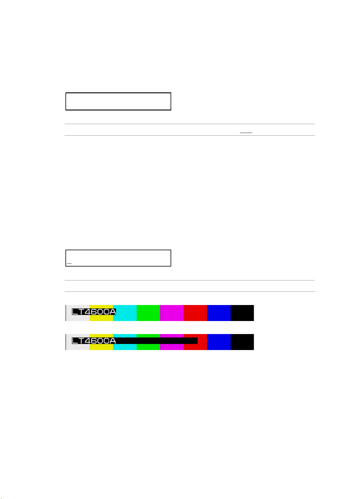
10. SDI OUTPUT (SDI SETTING)
3.ID ON/OFF
□ON ■OFF
3.CHARACTER SET
L
T4600A
10.7 Setting ID Characters
10.7.1 Turning ID Characters On and Off
To turn ID characters on and off, follow the procedure below.
If the check field pattern is selected, the ID characters will not be displayed even if this is
set to ON.
Procedure
SDI SETTING → SDI → ID CHARACTER → ID ON/OFF: ON / OFF
10.7.2 Creating ID Characters
To create ID characters, follow the procedure below.
The characters that you can use are as follows. You can enter up to 20 characters.
!”# $%&’()*+,-./ 0123456789:;<=>?@
▲
ABCDEFGHIJKLMNOPQRSTUVWXYZ[\]^_→←
The ID character background is displayed in black for 20 characters worth. If you enter “
▲
”
at the end of the ID character string, only the background of the entered characters will be
displayed in black. (“
If you enter “
” in the middle of the ID character string, characters after this character will
▲
” will not appear.)
▲
disappear, and you will not be able to edit them.
Procedure
SDI SETTING → SDI → ID CHARACTER → CHARACTER SET: LT4600A
▲
CHARACTER SET = LT4600A▲
CHARACTER SET = LT4600A
59
Page 70
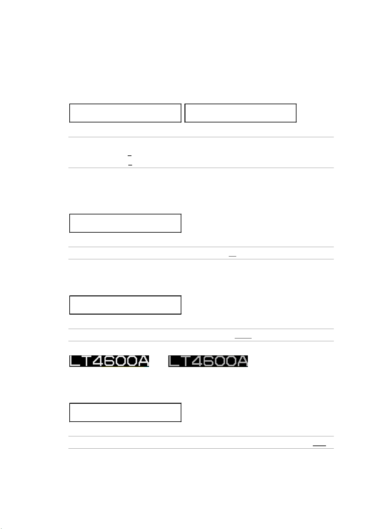
10. SDI OUTPUT (SDI SETTING)
3.ID V-POSITION
0 dot
3.ID H-POSITION
0 dot
3.ID SIZE
■x1 □x2 □x4 □x8
3.ID LEVEL
■100% □75%
4.ID BLINK ON/OFF
□ON ■OFF
10.7.3 Setting the Position of ID Characters
To set the position of the ID characters, follow the procedure below.
The values represent the coordinates at the upper left corner of the ID characters. The
upper left corner of the pattern is 0.
The value takes effect immediately. Pressing CANCEL does not revert the setting to the
previous value.
Procedure
SDI SETTING → SDI → ID CHARACTER
→ ID V-POSITION: 0 - +1079 (vertical direction)
→ ID H-POSITION: 0 - +1919 (horizontal direction)
10.7.4 Selecting the Size of ID Characters
To set the size of ID characters, follow the procedure below.
The size of ×1 is 32×32 dot/character.
Procedure
SDI SETTING → SDI → ID CHARACTER → ID SIZE: ×1 / ×2 / ×4 / ×8
10.7.5 Selecting the Level of ID Characters
To set the intensity level of ID characters, follow the procedure below.
Procedure
SDI SETTING → SDI → ID CHARACTER → ID LEVEL: 100% / 75%
ID LEVEL = 100% ID LEVEL = 75%
10.7.6 Turning ID Character Blinking On and Off
To turn ID character blinking on and off, follow the procedure below.
Procedure
SDI SETTING → SDI → ID CHARACTER → ID BLINK → ID BLINK ON/OFF: ON / OFF
60
Page 71
10. SDI OUTPUT (SDI SETTING)
4.ID BLINK ON TIME
+1 sec
4.ID BLINK OFF TIME
+1 sec
4.SCROLL ON/OFF
□ON ■OFF
4.DIRECTION
□LEFT ■RIGHT
4.SPEED
0 dot
10.7.7 Setting the ID Character Blinking Time
To set the ID character blinking time, follow the procedure below.
Procedure
SDI SETTING → SDI → ID CHARACTER → ID BLINK
→ ID BLINK ON TIME: +1 - +9 (on-time)
→ ID BLINK OFF TIME: +1 - +9 (off-time)
10.7.8 Turning ID Character Scrolling On and Off
To turn ID character scrolling on and off, follow the procedure below.
If set to ON, the ID characters scroll horizontally over the pattern.
Procedure
SDI SETTING → SDI → ID CHARACTER → ID SCROLL → SCROLL ON/OFF: ON / OFF
10.7.9 Selecting ID Character Scrolling Direction
To select the ID character scroll direction, follow the procedure below.
Procedure
SDI SETTING → SDI → ID CHARACTER → ID SCROLL → DIRECTION: LEFT / RIGHT
Settings
LEF T: Scrolls from right to left.
RIGHT: Scrolls from left to right.
10.7.10 Setting ID Character Scroll Speed
To set the ID character scroll speed, follow the procedure below.
The unit is dot/field (frame). If the speed is set to 0, the pattern will not scroll.
The value takes effect immediately. Pressing CANCEL does not revert the setting to the
previous value.
Procedure
SDI SETTING → SDI → ID CHARACTER → ID SCROLL → SPEED: 0 - +256 (2 dot steps)
61
Page 72
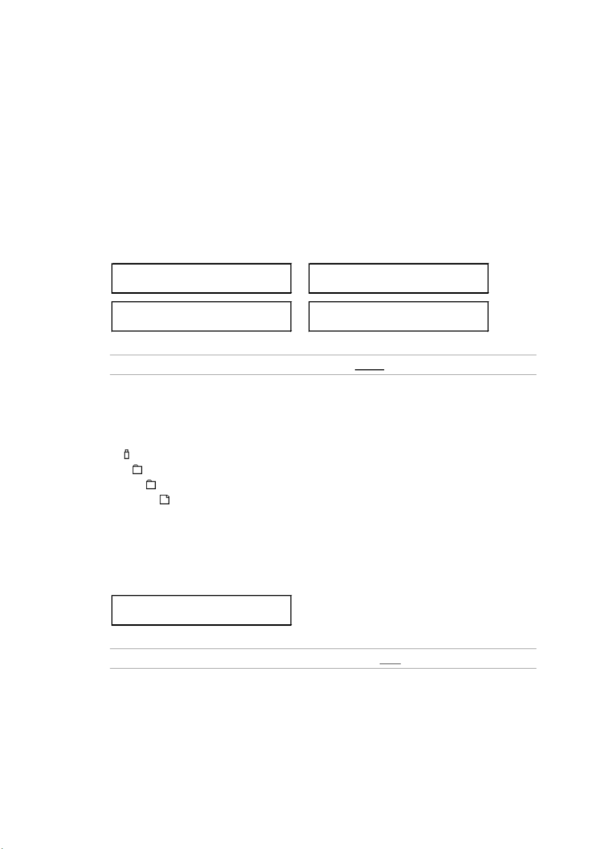
10.8 Setting Logos
3.LOGO SELECT
*NO DATA INT_1
DATA TRANSFER OK ?
■OK □CANCEL
3.LOGO SELECT
LEADER.LG 1/99
DATA TRANSFER OK ?
■OK □CANCEL
3.LOGO ON/OFF
□ON ■OFF
The logos (.lg format) that you create with the supplied Logo Application can be imported into
the LT 4600A and overlaid on SDI signals.
10.8.1 Loading a Logo
10. SDI OUTPUT (SDI SETTING)
To display a logo, you need to load it first.
You can either load a logo that has been imported into the LT 4600A according to section
6.4.2, “Importing a Logo,” or load a logo directly from a USB memory device.
To load a logo, follow the procedure below.
In LOGO SELECT, INT_1 to INT_4 represent imported logos, and 1 to 99 represent logos
stored in the USB memory device.
Procedure
SDI SETTING → SDI → LOGO → LOGO SELECT: INT_1 - INT_4 / 1 - 99
● USB Memory Device File Structure
Place logos in the LOGO folder of the USB memory device. Up to 99 logos can be
selected from the LT 4600A. If a logo is already loaded, it is overwritten.
USB memory device
LT4600A
└
└
└
LOGO
****.LG
10.8.2 Turning the Logo On and Off
To turn the logo on and off, follow the procedure below.
If the check field pattern is selected or if a logo has not been loaded into the LT 4600A, no
logo will be displayed even if this is set to ON.
Procedure
SDI SETTING → SDI → LOGO → LOGO ON/OFF: ON / OFF
62
Page 73
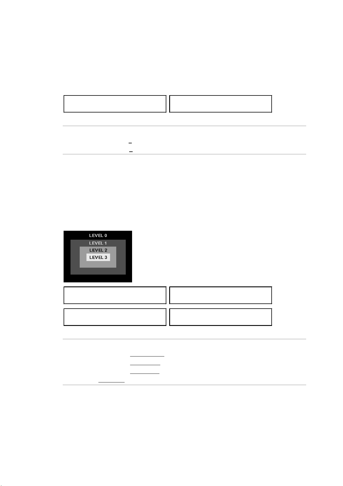
10.8.3 Setting the Logo Position
3.LOGO V-POSITION
0 dot
3.LOGO H-POSITION
0 dot
4.LEVEL 3
EB0h (100%)
4.LEVEL 2
A20h ( 66%)
4.LEVEL 1
590h ( 33%)
4.LEVEL 0
100h ( 0%)
To set the logo position, follow the procedure below.
The values represent the coordinates at the upper left corner of logo. The upper left corner
of the pattern is 0.
The value takes effect immediately. Pressing CANCEL does not revert the setting to the
previous value.
10. SDI OUTPUT (SDI SETTING)
Procedure
SDI SETTING → SDI → LOGO
→ LOGO V-POSITION: 0 - +1079 (vertical direction)
→ LOGO H-POSITION: 0 - +1919 (horizontal direction)
10.8.4 Setting the Logo Level
To set the logo intensity level, follow the procedure below.
Logos are made of 4-level monochrome data (LEVEL 3, LEVEL 2, LEVEL 1, and LEVEL 0).
You can set the intensity level for each level.
If LOGO BACKGROUND is set to O F F, the intensity level for LEVEL 0 is invalid.
The value takes effect immediately. Pressing CANCEL does not revert the setting to the
previous value.
Procedure
SDI SETTING → SDI → LOGO → LOGO LEVEL
→ LEVEL 3: 100h(0%) - EB0h(100%)
→ LEVEL 2: 100h(0%) - A20h(66%) - EB0h(100%)
→ LEVEL 1: 100h(0%) - 590h(33%) - EB0h(100%)
→ LEVEL 0: 100h(0%) - EB0h(100%)
63
Page 74
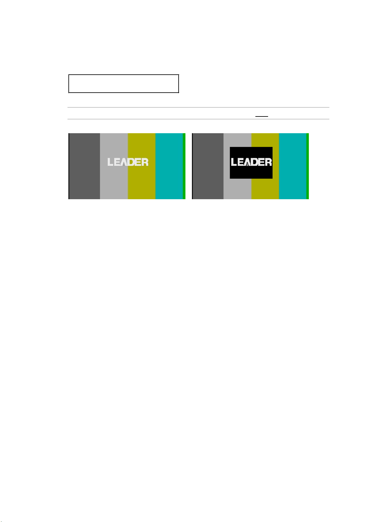
10. SDI OUTPUT (SDI SETTING)
3.LOGO BACKGROUND
□ON ■OFF
10.8.5 Selecting the Logo Background
To select whether to make the area set to LEVEL 0 transparent, follow the procedure
below.
Procedure
SDI SETTING → SDI → LOGO → LOGO BACKGROUND: ON / OFF
LOGO BACKGROUND = ON LOGO BACKGROUND = OFF
64
Page 75
10. SDI OUTPUT (SDI SETTING)
2.LIPSYNC
□ON ■OFF
10.9 Configuring Lip Sync
Combining the LT 4600A and our waveform monitor LV 5770(A) makes it possible to measure
the offset between the video signal and the audio signal that occurs in the transfer route for
each channel. Prepare an LV 5770(A) with an LV 5770SER08/09A and LV 5770SER41/43
installed. For information on how to use it, see the LV 5770SER08/09A instruction manual.
10.9.1 Turning Lip Sync On and Off
To turn lip sync on or off, follow the procedure below.
If set to ON, a lip sync pattern will be output.
If the check field pattern is selected, the pattern will not be output even if this is set to ON.
Procedure
SDI SETTING → SDI → LIPSYNC: ON / OFF
If set to ON, refer to section 10.4, “Configuring Embedded Audio,” and set all embedded
audio channels as shown below.
These settings are factory default settings.
Item Value
AUDIO ON/OFF ON
RESOLUTION 20 bits
EMPHASIS OFF
FREQUENCY 1kHz
LEVEL -20dBFS
65
Page 76
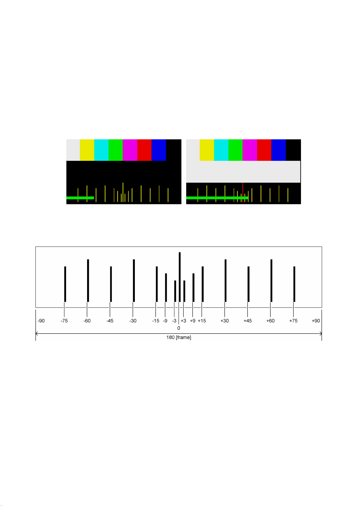
10. SDI OUTPUT (SDI SETTING)
10.9.2 Description of Lip Sync Patterns
A lip sync pattern is divided into three areas. From the top, they are the pattern, raster, and
scale areas. Audio is turned on or muted in sync with the image signal.
● Pattern
The pattern specified by PATTE RN is displayed.
Markers, ID characters, and logo are not displayed even if they are set to ON.
● Raster
If the scale slide bar is between 0 and +15 [frames], a white raster is displayed. If not, a
black raster is displayed.
● Scale
A green slide bar scrolls from left to right (approximately 6 seconds for 1080i/59.94).
The center scale turns red when the slide bar is between 0 and +15 [frames].
● Audio
If the scale slide bar is between 0 and +15 [frames], audio turns on. If not, audio is
muted.
The embedded audio click setting is invalid.
66
Page 77
11. AES/EBU DIGITAL AUDIO OUTPUT (AES/EBU SETTING)
2.AES/EBU TIMING
0 (512fs)
2.AUDIO ON/OFF
□ON ■OFF
2.RESOLUTION
■20bit □24bit
11. AES/EBU DIGITAL AUDIO OUTPUT (AES/EBU SETTING)
Two 48 kHz AES/EBU signals synchronized with video signals are output from the AES/EBU
connectors on the rear panel.
You can set the output signal using AES/EBU SETTING.
In AES/EBU SETTING, you can set the two signals separately. The procedure below is for
AES/EBU 1, but the same procedure can be applied to AES/EBU 2.
11.1 Adjusting the Timing
To adjust the AES/EBU signal relative to the reference signal, follow the procedure below.
The value takes effect immediately. Pressing CANCEL does not revert the setting to the
previous value.
Procedure
AES/EBU SETTING →AES/EBU 1 →
AES/EBU TIMING: -511 - 0 - +511 (±1 AES/EBU frame)
11.2 Turning the Audio On and Off
To turn the audio on or off, follow the procedure below.
Procedure
AES/EBU SETTING →AES/EBU 1 → AUDIO ON/OFF: ON / OFF
11.3 Selecting the Resolution
To select the resolution, follow the procedure below.
Procedure
AES/EBU SETTING →AES/EBU 1 → RESOLUTION: 20bit / 24bit
67
Page 78
11. AES/EBU DIGITAL AUDIO OUTPUT (AES/EBU SETTING)
2.EMPHASIS
□50/15 □CCITT ■OFF
4.EQUAL TO CH1
□ON ■OFF
4.FREQUENCY
*1kHz
4.LEVEL
-20 dBFS
11.4 Selecting the Pre-emphasis Mode
To select the pre-emphasis mode, follow the procedure below.
Procedure
AES/EBU SETTING →AES/EBU 1 → EMPHASIS: 50/15 / CCITT / OFF
11.5 Settings Shared by Channels
You can link the channel 2 setting to the channel 1 setting by following the procedure below to
select ON. It is possible to set the channel 2 setting even when this is set to ON, but the value
will be ignored.
Procedure
AES/EBU SETTING →AES/EBU 1 → CH SELECT → CH2 SETTING →
EQUAL TO CH1: ON / OFF
11.6 Selecting the Frequency
To select the frequency of the selected channel, follow the procedure below.
Procedure
AES/EBU SETTING →AES/EBU 1 → CH SELECT → CH* SETTING →
FREQUENCY: SILENCE / 400Hz / 800Hz / 1kHz
11.7 Setting the Level
To set the level of the selected channel, follow the procedure below.
Procedure
AES/EBU SETTING →AES/EBU 1 → CH SELECT → CH* SETTING → LEVEL: -60 - -20 - 0
68
Page 79
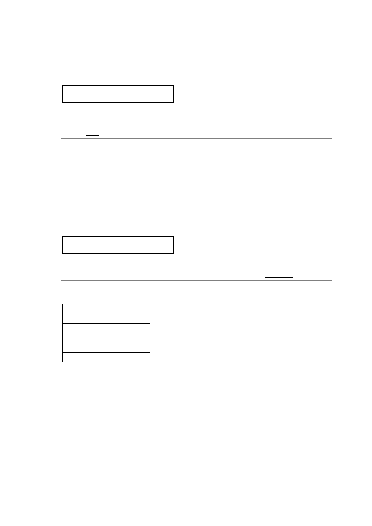
11. AES/EBU DIGITAL AUDIO OUTPUT (AES/EBU SETTING)
4.CLICK
*OFF
↵
2.LIPSYNC ENABLE
□ENABLE ■DISABLE
11.8 Setting Clicks
You can insert click sounds into the selected channel. Follow the procedure below to set the
insertion interval in the range of 1 sec to 4 sec.
This setting is valid when LIPSYNC ENABLE is set to DISABLE.
Procedure
AES/EBU SETTING →AES/EBU 1 → CH SELECT → CH* SETTING →
CLICK: OFF / 1sec / 2sec / 3sec / 4sec
11.9 Configuring Lip Sync
To select whether to output AES/EBU signals at the same timing as the lip sync audio signal,
follow the procedure below.
This setting is valid under the following conditions.
• When the output signal is 3G-A, HD, or SD, and SDI 1 lip sync is set to ON (see section
10.9.1, “Turning Lip Sync On and Off”)
• When the output signal is 3G-B or HD(DL), and lip sync is set to ON (see section 10.9.1,
“Turning Lip Sync On and Off”)
Procedure
AES/EBU SETTING →AES/EBU 1 → LIPSYNC ENABLE: ENABLE / DISABLE
If set to ENABLE, set all AES/EBU signal channels as shown below.
Item Value
AUDIO ON/OFF ON
RESOLUTION 20bit
EMPHASIS OFF
FREQUENCY 1kHz
LEVEL -20dBFS
69
Page 80
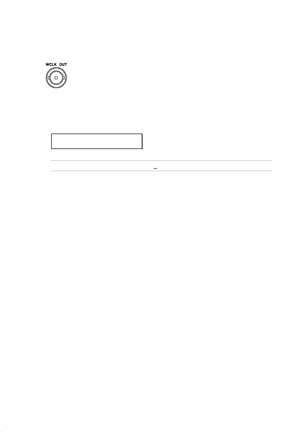
12. WORD-CLOCK OUTPUT (WCLK SETTING)
1.WCLK TIMING
0 (512fs)
12. WORD-CLOCK OUTPUT (WCLK SETTING)
A 48 kHz word-clock signal synchronized to the video signal is output from the WCLK OUT
12.1 Adjusting the Timing
connector on the rear panel. You can set the output signal using WCLK SETT I N G.
To adjust the word-clock signal relative to the reference signal, follow the procedure below.
The value takes effect immediately. Pressing CANCEL does not revert the setting to the
previous value.
Procedure
WCLK SETTING → WCLK TIMING: -511 - 0 - +511 (±1 AES/EBU frame)
70
Page 81

13. SNMP
By using SNMP (Simple Network Management Protocol), you can check the LT 4600A status
from an SNMP manager. In addition, when the fan stops or other errors occur, traps can be sent
from the LT 4600A to an SNMP manager.
* The Ethernet features of the LT 4600A have only been confirmed to work in a local network environment.
LEADER does not guarantee that they will work in any network environment.
* DHCP client and DNS resolver features are not supported.
13.1 SNMP Version
SNMPv1
13.2 SMI Definitions
IMPORTS
MODULE-IDENTITY, OBJECT-TYPE, NOTIFICATION-TYPE, enterprises
FROM SNMPv2-SMI
DisplayString
FROM SNMPv2-TC
OBJECT-GROU P, MODULE-COMPLIANCE
FROM SNMPv2-CONF;
13.3 Procedure
13. SNMP
1. On the LT 4600A, set the IP address.
Use UTILITY SETTING > ETHERNET > NETWORK SETTING.
Then, restart the LT 4600A according to the displayed instructions. The specified value
takes effect after you restart the LT 4600A.
2. Connect the LT 4600A’s Ethernet port to the network.
Connect to a network with an SNMP manager.
3. On the PC, start an SNMP manager.
An SNMP manager is not supplied with the LT 4600A. Please obtain it separately.
For details on how to use the SNMP manager, see its instruction manual.
Set the community names.
Use UTILITY SETTING > ETHERNET > SNMP COMMUNITY.
By default, the following community names are assigned.
Read Community: LDRUser
Write Community: LDRAdm
Trap Community: LDRUser
71
Page 82

4. On the SNMP manager, set the IP address of the trap transmission destination.
OID: 1.3.6.1.4.1.leader(20111).lt4600(28).trap(100).target(1).managerIp(1).0
You can also set it from the LT 4600A menu.
5. On the SNMP manager, set trap transmission to enable(1).
OID: 1.3.6.1.4.1.leader(20111).lt4600(28).trap(100).target(1).trapAction(2).0
You can also set it from the LT 4600A menu.
6. Restart the LT 4600A.
7. When the LT 4600A restarts, check that the standard trap "ColdStart" is received by the
SNMP manager.
13.4 Enterprise MIB
● Retrieving the MIB File
Copy the file from the LT 4600A to a USB memory device.
Connect a USB memory device to the LT 4600A, and from the menu, select UTILITY
SETTING > ETHERNET > GET MIB FILE > OK. The file LT4600-MIB.mib will be copied to
the USB memory device.
For details on how to use the MIB file, see the instruction manual for the SNMP manager.
Reference Section 6.5.5, “Retrieving the MIB File”
● Enterprise Number
13. SNMP
Leader’s enterprise number is 20111.
iso(1).org(3).dod(6).internet(1).private(4).enterprises(1).leader(20111)
● MIB Structure
lt4600 OBJECT IDENTIFIER ::= { leader 28 }
standard OBJECT IDENTIFIER ::= { lt4600 1 }
status OBJECT IDENTIFIER ::= { standard 1 }
fanUnit OBJECT IDENTIFIER
::= { status 1 }
genlockSts OBJECT IDENTIFIER ::= { status 2 }
reference OBJECT IDENTIFIER ::= { standard 2 }
analogBlack OBJECT IDENTIFIER ::= { standard 3 }
output1 OBJECT IDENTIFIER ::= { analogBlack 1 }
output2 OBJECT IDENTIFIER ::= { analogBlack 2 }
output3 OBJECT IDENTIFIER ::= { analogBlack 3 }
serialDigital OBJECT IDENTIFIER ::= { standard 4 }
sdi1 OBJECT IDENTIFIER ::= { serialDigital 1 }
sdi2 OBJECT IDENTIFIER ::= { serialDigital 2 }
trap OBJECT IDENTIFIER ::= { lt4600 100 }
target OBJECT IDENTIFIER ::= { trap 1 }
● ACCESS
In the tables, "ACCESS" indicates the following:
72
Page 83

RO: Read only.
R/W: Read and write.
13. SNMP
73
Page 84
13. SNMP
13.4.1 status Group
● fanUnit(1) Group
MIB OID SYNTAX ACCESS VA LUE Description
fanStatus fanUnit.1 INTEGER RO 2 stop
3 operation
● genlockSts(2) Group
MIB OID SYNTAX ACCESS VA LUE Description
genStatus genlockSts.1 INTEGER RO 1 disable
2 internal
3 unlock
4 locked
5 stay-in-sync
13.4.2 reference Group
MIB OID SYNTAX ACCESS VA LUE Description
genMode reference.1 INTEGER RO 1 internal
2 stay-in-sync
genFormat reference.2 INTEGER RO 1 1125i/60
2 1125i/59.94
3 1125i/50
4 1125p/30
5 1125p/29.97
6 1125p/25
7 1125p/24
8 1125p/23.98
9 1125psF/24
10 1125psF/23.98
21 750p/60
22 750p/59.94
23 750p/50
24 750p/30
25 750p/29.97
26 750p/25
27 750p/24
28 750p/23.98
41 NTSC BB
42 NTSC BB+REF
43 NTSC BB+ID
44 NTSC BB+REF+ID
49 525i/59.94
50 525p/59.94
61 PAL BB
62 PAL BB+REF
63 625i/50
74
Page 85
13. SNMP
MIB OID SYNTAX ACCESS VA LUE Description
64 625p/50
13.4.3 analogBlack Group
● output1(1) Group
MIB OID SYNTAX ACCESS VA LUE Description
blk1Format output1.1 INTEGER RO 1 1080i/60
2 1080i/59.94
3 1080i/50
4 1080p/30
5 1080p/29.97
6 1080p/25
7 1080p/24
8 1080p/23.98
15 1080psF/24
16 1080psF/23.98
21 720p/60
22 720p/59.94
23 720p/50
24 720p/30
25 720p/29.97
26 720p/25
27 720p/24
28 720p/23.98
41 NTSC BB
42 NTSC BB+REF
43 NTSC BB+ID
44 NTSC BB+REF+ID
45 NTSC BB+SETUP
46 NTSC BB+S+REF
47 NTSC BB+S+ID
48 NTSC BB+S+R+ID
49 525i/59.94
50 525p/59.94
61 PAL BB
62 PAL BB+REF
63 625i/50
64 625p/50
75
Page 86
13. SNMP
● output2(2) Group
MIB OID SYNTAX ACCESS VA LUE Description
blk2Format output2.1 INTEGER RO Same as output1(1) group
● output3(3) Group
MIB OID SYNTAX ACCESS VA LUE Description
blk3Format output3.1 INTEGER RO Same as output1(1) group
13.4.4 serialDigital Group
● sdi1(1) Group
MIB OID SYNTAX ACCESS VA LUE Description
sdi1Format sdi1.1 INTEGER RO 4 3G-A 422(YCbCr) 10 bit 1080p/60
5 3G-A 422(YCbCr) 10 bit 1080p/59.94
6 3G-A 422(YCbCr) 10 bit 1080p/50
1001 3G-A 422(YCbCr) 12 bit 1080i/60
1002 3G-A 422(YCbCr) 12 bit 1080i/59.94
1003 3G-A 422(YCbCr) 12 bit 1080i/50
1007 3G-A 422(YCbCr) 12 bit 1080p/30
1008 3G-A 422(YCbCr) 12 bit 1080p/29.97
1009 3G-A 422(YCbCr) 12 bit 1080p/25
1010 3G-A 422(YCbCr) 12 bit 1080p/24
1011 3G-A 422(YCbCr) 12 bit 1080p/23.98
1012 3G-A 422(YCbCr) 12 bit 1080psF/30
1013 3G-A 422(YCbCr) 12 bit 1080psF/29.97
1014 3G-A 422(YCbCr) 12 bit 1080psF/25
1015 3G-A 422(YCbCr) 12 bit 1080psF/24
1016 3G-A 422(YCbCr) 12 bit 1080psF/23.98
2001 3G-A 444(YCbCr) 10 bit 1080i/60
2002 3G-A 444(YCbCr) 10 bit 1080i/59.94
2003 3G-A 444(YCbCr) 10 bit 1080i/50
2007 3G-A 444(YCbCr) 10 bit 1080p/30
2008 3G-A 444(YCbCr) 10 bit 1080p/29.97
2009 3G-A 444(YCbCr) 10 bit 1080p/25
2010 3G-A 444(YCbCr) 10 bit 1080p/24
2011 3G-A 444(YCbCr) 10 bit 1080p/23.98
2012 3G-A 444(YCbCr) 10 bit 1080psF/30
2013 3G-A 444(YCbCr) 10 bit 1080psF/29.97
2014 3G-A 444(YCbCr) 10 bit 1080psF/25
2015 3G-A 444(YCbCr) 10 bit 1080psF/24
2016 3G-A 444(YCbCr) 10 bit 1080psF/23.98
2021 3G-A 444(YCbCr) 10 bit 720p/60
2022 3G-A 444(YCbCr) 10 bit 720p/59.94
2023 3G-A 444(YCbCr) 10 bit 720p/50
2024 3G-A 444(YCbCr) 10 bit 720p/30
2025 3G-A 444(YCbCr) 10 bit 720p/29.97
76
Page 87
13. SNMP
MIB OID SYNTAX ACCESS VA LUE Description
2026 3G-A 444(YCbCr) 10 bit 720p/25
2027 3G-A 444(YCbCr) 10 bit 720p/24
2028 3G-A 444(YCbCr) 10 bit 720p/23.98
3001 3G-A 444(YCbCr) 12 bit 1080i/60
3002 3G-A 444(YCbCr) 12 bit 1080i/59.94
3003 3G-A 444(YCbCr) 12 bit 1080i/50
3007 3G-A 444(YCbCr) 12 bit 1080p/30
3008 3G-A 444(YCbCr) 12 bit 1080p/29.97
3009 3G-A 444(YCbCr) 12 bit 1080p/25
3010 3G-A 444(YCbCr) 12 bit 1080p/24
3011 3G-A 444(YCbCr) 12 bit 1080p/23.98
4001 3G-A 444(RGB) 10 bit 1080i/60
4002 3G-A 444(RGB) 10 bit 1080i/59.94
4003 3G-A 444(RGB) 10 bit 1080i/50
4007 3G-A 444(RGB) 10 bit 1080p/30
4008 3G-A 444(RGB) 10 bit 1080p/29.97
4009 3G-A 444(RGB) 10 bit 1080p/25
4010 3G-A 444(RGB) 10 bit 1080p/24
4011 3G-A 444(RGB) 10 bit 1080p/23.98
4012 3G-A 444(RGB) 10 bit 1080psF/30
4013 3G-A 444(RGB) 10 bit 1080psF/29.97
4014 3G-A 444(RGB) 10 bit 1080psF/25
4015 3G-A 444(RGB) 10 bit 1080psF/24
4016 3G-A 444(RGB) 10 bit 1080psF/23.98
4021 3G-A 444(RGB) 10 bit 720p/60
4022 3G-A 444(RGB) 10 bit 720p/59.94
4023 3G-A 444(RGB) 10 bit 720p/50
4024 3G-A 444(RGB) 10 bit 720p/30
4025 3G-A 444(RGB) 10 bit 720p/29.97
4026 3G-A 444(RGB) 10 bit 720p/25
4027 3G-A 444(RGB) 10 bit 720p/24
4028 3G-A 444(RGB) 10 bit 720p/23.98
5001 3G-A 444(RGB) 12 bit 1080i/60
5002 3G-A 444(RGB) 12 bit 1080i/59.94
5003 3G-A 444(RGB) 12 bit 1080i/50
5007 3G-A 444(RGB) 12 bit 1080p/30
5008 3G-A 444(RGB) 12 bit 1080p/29.97
5009 3G-A 444(RGB) 12 bit 1080p/25
5010 3G-A 444(RGB) 12 bit 1080p/24
5011 3G-A 444(RGB) 12 bit 1080p/23.98
10001 HD 422(YCbCr) 10 bit 1080i/60
10002 HD 422(YCbCr) 10 bit 1080i/59.94
10003 HD 422(YCbCr) 10 bit 1080i/50
10007 HD 422(YCbCr) 10 bit 1080p/30
10008 HD 422(YCbCr) 10 bit 1080p/29.97
77
Page 88
13. SNMP
MIB OID SYNTAX ACCESS VA LUE Description
10009 HD 422(YCbCr) 10 bit 1080p/25
10010 HD 422(YCbCr) 10 bit 1080p/24
10011 HD 422(YCbCr) 10 bit 1080p/23.98
10015 HD 422(YCbCr) 10 bit 1080psF/24
10016 HD 422(YCbCr) 10 bit 1080psF/23.98
10021 HD 422(YCbCr) 10 bit 720p/60
10022 HD 422(YCbCr) 10 bit 720p/59.94
10023 HD 422(YCbCr) 10 bit 720p/50
10024 HD 422(YCbCr) 10 bit 720p/30
10025 HD 422(YCbCr) 10 bit 720p/29.97
10026 HD 422(YCbCr) 10 bit 720p/25
10027 HD 422(YCbCr) 10 bit 720p/24
10028 HD 422(YCbCr) 10 bit 720p/23.98
10049 HD 422(YCbCr) 10 bit 525i/59.94
10063 HD 422(YCbCr) 10 bit 625i/50
20004 3G-B 422(YCbCr) 10 bit 1080p/60
20005 3G-B 422(YCbCr) 10 bit 1080p/59.94
20006 3G-B 422(YCbCr) 10 bit 1080p/50
21001 3G-B 422(YCbCr) 12 bit 1080i/60
21002 3G-B 422(YCbCr) 12 bit 1080i/59.94
21003 3G-B 422(YCbCr) 12 bit 1080i/50
21007 3G-B 422(YCbCr) 12 bit 1080p/30
21008 3G-B 422(YCbCr) 12 bit 1080p/29.97
21009 3G-B 422(YCbCr) 12 bit 1080p/25
21010 3G-B 422(YCbCr) 12 bit 1080p/24
21011 3G-B 422(YCbCr) 12 bit 1080p/23.98
21012 3G-B 422(YCbCr) 12 bit 1080psF/30
21013 3G-B 422(YCbCr) 12 bit 1080psF/29.97
21014 3G-B 422(YCbCr) 12 bit 1080psF/25
21015 3G-B 422(YCbCr) 12 bit 1080psF/24
21016 3G-B 422(YCbCr) 12 bit 1080psF/23.98
22001 3G-B 444(YCbCr) 10 bit 1080i/60
22002 3G-B 444(YCbCr) 10 bit 1080i/59.94
22003 3G-B 444(YCbCr) 10 bit 1080i/50
22007 3G-B 444(YCbCr) 10 bit 1080p/30
22008 3G-B 444(YCbCr) 10 bit 1080p/29.97
22009 3G-B 444(YCbCr) 10 bit 1080p/25
22010 3G-B 444(YCbCr) 10 bit 1080p/24
22011 3G-B 444(YCbCr) 10 bit 1080p/23.98
22012 3G-B 444(YCbCr) 10 bit 1080psF/30
22013 3G-B 444(YCbCr) 10 bit 1080psF/29.97
22014 3G-B 444(YCbCr) 10 bit 1080psF/25
22015 3G-B 444(YCbCr) 10 bit 1080psF/24
22016 3G-B 444(YCbCr) 10 bit 1080psF/23.98
23001 3G-B 444(YCbCr) 12 bit 1080i/60
78
Page 89
13. SNMP
MIB OID SYNTAX ACCESS VA LUE Description
23002 3G-B 444(YCbCr) 12 bit 1080i/59.94
23003 3G-B 444(YCbCr) 12 bit 1080i/50
23007 3G-B 444(YCbCr) 12 bit 1080p/30
23008 3G-B 444(YCbCr) 12 bit 1080p/29.97
23009 3G-B 444(YCbCr) 12 bit 1080p/25
23010 3G-B 444(YCbCr) 12 bit 1080p/24
23011 3G-B 444(YCbCr) 12 bit 1080p/23.98
24001 3G-B 444(RGB) 10 bit 1080i/60
24002 3G-B 444(RGB) 10 bit 1080i/59.94
24003 3G-B 444(RGB) 10 bit 1080i/50
24007 3G-B 444(RGB) 10 bit 1080p/30
24008 3G-B 444(RGB) 10 bit 1080p/29.97
24009 3G-B 444(RGB) 10 bit 1080p/25
24010 3G-B 444(RGB) 10 bit 1080p/24
24011 3G-B 444(RGB) 10 bit 1080p/23.98
24012 3G-B 444(RGB) 10 bit 1080psF/30
24013 3G-B 444(RGB) 10 bit 1080psF/29.97
24014 3G-B 444(RGB) 10 bit 1080psF/25
24015 3G-B 444(RGB) 10 bit 1080psF/24
24016 3G-B 444(RGB) 10 bit 1080psF/23.98
25001 3G-B 444(RGB) 12 bit 1080i/60
25002 3G-B 444(RGB) 12 bit 1080i/59.94
25003 3G-B 444(RGB) 12 bit 1080i/50
25007 3G-B 444(RGB) 12 bit 1080p/30
25008 3G-B 444(RGB) 12 bit 1080p/29.97
25009 3G-B 444(RGB) 12 bit 1080p/25
25010 3G-B 444(RGB) 12 bit 1080p/24
25011 3G-B 444(RGB) 12 bit 1080p/23.98
30004 HD(DL) 422(YCbCr) 10 bit 1080p/60
30005 HD(DL) 422(YCbCr) 10 bit 1080p/59.94
30006 HD(DL) 422(YCbCr) 10 bit 1080p/50
31001 HD(DL) 422(YCbCr) 12 bit 1080i/60
31002 HD(DL) 422(YCbCr) 12 bit 1080i/59.94
31003 HD(DL) 422(YCbCr) 12 bit 1080i/50
31007 HD(DL) 422(YCbCr) 12 bit 1080p/30
31008 HD(DL) 422(YCbCr) 12 bit 1080p/29.97
31009 HD(DL) 422(YCbCr) 12 bit 1080p/25
31010 HD(DL) 422(YCbCr) 12 bit 1080p/24
31011 HD(DL) 422(YCbCr) 12 bit 1080p/23.98
31012 HD(DL) 422(YCbCr) 12 bit 1080psF/30
31013 HD(DL) 422(YCbCr) 12 bit 1080psF/29.97
31014 HD(DL) 422(YCbCr) 12 bit 1080psF/25
31015 HD(DL) 422(YCbCr) 12 bit 1080psF/24
31016 HD(DL) 422(YCbCr) 12 bit 1080psF/23.98
32001 HD(DL) 444(YCbCr) 10 bit 1080i/60
79
Page 90
13. SNMP
MIB OID SYNTAX ACCESS VA LUE Description
32002 HD(DL) 444(YCbCr) 10 bit 1080i/59.94
32003 HD(DL) 444(YCbCr) 10 bit 1080i/50
32007 HD(DL) 444(YCbCr) 10 bit 1080p/30
32008 HD(DL) 444(YCbCr) 10 bit 1080p/29.97
32009 HD(DL) 444(YCbCr) 10 bit 1080p/25
32010 HD(DL) 444(YCbCr) 10 bit 1080p/24
32011 HD(DL) 444(YCbCr) 10 bit 1080p/23.98
32012 HD(DL) 444(YCbCr) 10 bit 1080psF/30
32013 HD(DL) 444(YCbCr) 10 bit 1080psF/29.97
32014 HD(DL) 444(YCbCr) 10 bit 1080psF/25
32015 HD(DL) 444(YCbCr) 10 bit 1080psF/24
32016 HD(DL) 444(YCbCr) 10 bit 1080psF/23.98
33001 HD(DL) 444(YCbCr) 12 bit 1080i/60
33002 HD(DL) 444(YCbCr) 12 bit 1080i/59.94
33003 HD(DL) 444(YCbCr) 12 bit 1080i/50
33007 HD(DL) 444(YCbCr) 12 bit 1080p/30
33008 HD(DL) 444(YCbCr) 12 bit 1080p/29.97
33009 HD(DL) 444(YCbCr) 12 bit 1080p/25
33010 HD(DL) 444(YCbCr) 12 bit 1080p/24
33011 HD(DL) 444(YCbCr) 12 bit 1080p/23.98
33012 HD(DL) 444(YCbCr) 12 bit 1080psF/30
33013 HD(DL) 444(YCbCr) 12 bit 1080psF/29.97
33014 HD(DL) 444(YCbCr) 12 bit 1080psF/25
33015 HD(DL) 444(YCbCr) 12 bit 1080psF/24
33016 HD(DL) 444(YCbCr) 12 bit 1080psF/23.98
34001 HD(DL) 444(RGB) 10 bit 1080i/60
34002 HD(DL) 444(RGB) 10 bit 1080i/59.94
34003 HD(DL) 444(RGB) 10 bit 1080i/50
34007 HD(DL) 444(RGB) 10 bit 1080p/30
34008 HD(DL) 444(RGB) 10 bit 1080p/29.97
34009 HD(DL) 444(RGB) 10 bit 1080p/25
34010 HD(DL) 444(RGB) 10 bit 1080p/24
34011 HD(DL) 444(RGB) 10 bit 1080p/23.98
34012 HD(DL) 444(RGB) 10 bit 1080psF/30
34013 HD(DL) 444(RGB) 10 bit 1080psF/29.97
34014 HD(DL) 444(RGB) 10 bit 1080psF/25
34015 HD(DL) 444(RGB) 10 bit 1080psF/24
34016 HD(DL) 444(RGB) 10 bit 1080psF/23.98
35001 HD(DL) 444(RGB) 12 bit 1080i/60
35002 HD(DL) 444(RGB) 12 bit 1080i/59.94
35003 HD(DL) 444(RGB) 12 bit 1080i/50
35007 HD(DL) 444(RGB) 12 bit 1080p/30
35008 HD(DL) 444(RGB) 12 bit 1080p/29.97
35009 HD(DL) 444(RGB) 12 bit 1080p/25
35010 HD(DL) 444(RGB) 12 bit 1080p/24
80
Page 91
13. SNMP
MIB OID SYNTAX ACCESS VA LUE Description
35011 HD(DL) 444(RGB) 12 bit 1080p/23.98
35012 HD(DL) 444(RGB) 12 bit 1080psF/30
35013 HD(DL) 444(RGB) 12 bit 1080psF/29.97
35014 HD(DL) 444(RGB) 12 bit 1080psF/25
35015 HD(DL) 444(RGB) 12 bit 1080psF/24
35016 HD(DL) 444(RGB) 12 bit 1080psF/23.98
sdi1Pattern sdi1.2 INTEGER RO 1 Color Bar 100%
2 Color Bar 75%
3 Multi CB 100%
4 Multi CB 75%
5 Multi CB (+I)
6 SMPTE Color Bar
7 EBU Color Bar
8 BBC Color Bar
9 Check Field
10 Blue Field
11 Green Field
12 Red Field
13 Flat Field 0%
14 Flat Field 100%
1001 Color Bar 100% (LIPSYNC: ON)
1002 Color Bar 75% (LIPSYNC: ON)
1003 Multi CB 100% (LIPSYNC: ON)
1004 Multi CB 75% (LIPSYNC: ON)
1005 Multi CB (+I) (LIPSYNC: ON)
1006 SMPTE Color Bar (LIPSYNC: ON)
1007 EBU Color Bar (LIPSYNC: ON)
1008 BBC Color Bar (LIPSYNC: ON)
1010 Blue Field (LIPSYNC: ON)
1011 Green Field (LIPSYNC: ON)
1012 Red Field (LIPSYNC: ON)
1013 Flat Field 0% (LIPSYNC: ON)
1014 Flat Field 100% (LIPSYNC: ON)
sdi1Scroll sdi1.3 INTEGER RO 1 Off
2 On
sdi1Vtiming sdi1.4 INTEGER RO ±1124 -
sdi1Htiming sdi1.5 INTEGER RO ±4124 -
sdi1Emb-audio sdi1.6 INTEGER RO 1 G1: OFF G2: OFF G3: OFF G4: OFF
2 G1: OFF G2: OFF G3: OFF G4: ON
3 G1: OFF G2: OFF G3: ON G4: OFF
4 G1: OFF G2: OFF G3: ON G4: ON
5 G1: OFF G2: ON G3: OFF G4: OFF
6 G1: OFF G2: ON G3: OFF G4: ON
7 G1: OFF G2: ON G3: ON G4: OFF
8 G1: OFF G2: ON G3: ON G4: ON
81
Page 92
13. SNMP
MIB OID SYNTAX ACCESS VA LUE Description
9 G1: ON G2: OFF G3: OFF G4: OFF
10 G1: ON G2: OFF G3: OFF G4: ON
11 G1: ON G2: OFF G3: ON G4: OFF
12 G1: ON G2: OFF G3: ON G4: ON
13 G1: ON G2: ON G3: OFF G4: OFF
14 G1: ON G2: ON G3: OFF G4: ON
15 G1: ON G2: ON G3: ON G4: OFF
16 G1: ON G2: ON G3: ON G4: ON
sdi1YCbCr-onoff sdi1.7 INTEGER RO 1 Y: OFF Cb: OFF Cr: OFF
2 Y: OFF Cb: OFF Cr: ON
3 Y: OFF Cb: ON Cr: OFF
4 Y: OFF Cb: ON Cr: ON
5 Y: ON Cb: OFF Cr: OFF
6 Y: ON Cb: OFF Cr: ON
7 Y: ON Cb: ON Cr: OFF
8 Y: ON Cb: ON Cr: ON
sdi1Safty90area sdi1.8 INTEGER RO 1 Off
2 On
sdi1Safty80area sdi1.9 INTEGER RO 1 Off
2 On
sdi1Safty43area sdi1.10 INTEGER RO 1 Off
2 On
sdi1Id-charactor sd i1. 11 INTEGER RO 1 Off
2 On
sdi1Logo sdi1.12 INTEGER RO 1 Off
2 On
● sdi2(2) Group
MIB OID SYNTAX ACCESS VA LUE Description
sdi2Format sdi2.1 INTEGER RO Same as sdi1(1) group
sdi2Pattern sdi2.2 INTEGER RO
sdi2Scroll sdi2.3 INTEGER RO
sdi2Vtiming sdi2.4 INTEGER RO
sdi2Htiming sdi2.5 INTEGER RO
sdi2Emb-audio sdi2.6 INTEGER RO
sdi2YCbCr-onoff sdi2.7 INTEGER RO
sdi2Safty90area sdi2.8 INTEGER RO
sdi2Safty80area sdi2.9 INTEGER RO
sdi2Safty43area sdi2.10 INTEGER RO
sdi2Id-charactor sd i2. 11 INTEGER RO
sdi2Logo sdi2.12 INTEGER RO
82
Page 93

13. SNMP
13.4.5 trap Group
● target(1) Group
MIB OID SYNTAX ACCESS VA LUE Description
managerIp target.1 IP ADDRESS R/W *.*.*.* Trap transmission destination
trapAction target.2 INTEGER R/W 1 enable
2 disable
13.5 Extended TRAP
ID Event Name Description Object Data
1 fanUnitStatus Fan unit status change detection fanUnit.status
10 genlockSignalStatus Genlock status change detection genlockSts.status
83
Page 94
14. APPENDIX
14.1 List of Settings
A list of settings that you can specify on the LT 4600A is provided below. The description of
each item is as follows:
Presets Y Items that are saved to presets
N Items that are not saved to presets
Last memory Y At startup, settings that are set to those that were in use the last time the power was
turned off
M Settings that are initialized at startup when POWER ON RECALL is set to OFF
Settings that are set to those of the preset at startup when POWER ON RECALL is
set to a value between NUMBER 0 and 9
For details on POWER ON RECALL, see section 6.3.3, “Power-on Settings.”
N Settings that are set to their factory defaults at startup
14.1.1 UTILITY SETTING
14. APPENDIX
Setting Value (Maximum)
LCD BACK LIGHT ON / OFF ON N Y
KEY LOCK ON / OFF OFF N Y
POWER ON RECALL OFF / NUMBER 0 - NUMBER 9 OFF N Y
LOGO SELECT INT_1 - INT_4 INT_1 N Y
IP ADDRESS 000.000.000.000 - 255.255.255.255 192.168.000.000 N Y
SUBNET MASK 000.000.000.000 - 255.255.255.255 255.255.255.000 N Y
DEFAULT GATEWAY 000.000.000.000 - 255.255.255.255 000.000.000.000 N Y
ACTION ENABLE / DISABLE DISABLE N Y
MANAGER IP 000.000.000.000 - 255.255.255.255 192.168.000.000 N Y
READ COMMUNITY
WRITE COMMUNITY LDRAdm▲ N Y
TRAP COMMUNITY LDRUser▲ N Y
DATE & TIME ADJUST 2000/01/01 00:00:00 - 2099/12/31 23:59:59 2012/01/01
0123456789
▲
ABCDEFGHIJKLMNOPQRSTUVWXYZ
abcdefghijklmnopqrstuvwxyz
Factory
Default Value
LDRUser
00:00:00
Preset
N Y
▲
N N
Last
memory
84
Page 95

14.1.2 REFERENCE SETTING
14. APPENDIX
Setting Value (Maximum)
GENLOCK MODE INTERNAL / STAY-IN-SYNC INTERNAL Y M
LOCK FORMAT 1125i/60 / 1125i/59.94 / 1125i/50 /
1125p/30 / 1125p/29.97 / 1125p/25 /
1125p/24 / 1125p/23.98 / 1125psF/24 /
1125psF/23.98 / 750p/60 / 750p/59.94 /
750p/50 / 750p/30 / 750p/29.97 /
750p/25 / 750p/24 / 750p/23.98 /
525i/59.94 / NTSC BB / NTSC BB+REF /
NTSC BB+ID / NTSC BB+REF+ID /
525p/59.94 / 625i/50 / PAL BB /
PAL BB+REF / 625p/50
FINE PHASE ADJUST ±20 0 Y M
GENLOCK LOG ON/OFF ON / OFF OFF N N
Factory
Default Value
NTSC BB Y M
Preset
14.1.3 SYSTEM SETTING
Setting Value (Maximum)
SYSTEM SELECT 60.00Hz GROUP / 59.94Hz GROUP /
50.00Hz GROUP
MODE SELECT SDI 1 / 2 / 3G-LvB / DUAL SDI 1 / 2 Y M
SDI 1 3G-SDI-LvA / HD/SD-SDI HD/SD-SDI Y M
SDI 2 3G-SDI-LvA / HD/SD-SDI HD/SD-SDI Y M
3G-LvB/DUAL LINK 3G-SDI-LvB / HD DUAL LINK HD DUAL LINK Y M
Factory
Default Value
59.94Hz GROUP Y M
Preset
Last
memory
Last
memory
85
Page 96

14.1.4 BLACK SETTING
14. APPENDIX
Setting Value (Maximum)
BLK1 FORMAT 1080i/60 / 1080i/59.94 / 1080i/50 /
1080p/30 / 1080p/29.97 / 1080p/25 /
1080p/24 / 1080p/23.98 / 1080psF/24 /
1080psF/23.98 / 720p/60 / 720p/59.94 /
720p/50 / 720p/30 / 720p/29.97 /
720p/25 / 720p/24 / 720p/23.98 /
NTSC BB / NTSC BB+REF /
NTSC BB+ID / NTSC BB+REF+ID /
NTSC BB+SETUP / NTSC BB+S+REF /
NTSC BB+S+ID / NTSC BB+S+R+ID /
525i/59.94 / 525p/59.94 / PAL BB /
PAL BB+REF / 625i/50 / 625p/50
BLK1 F-PHASE ±5 0 Y M
BLK1 V-PHASE ±1124 0 Y M
BLK1 H-PHASE[dot] ±4124 0 Y M
BLK1 H-PHASE[μs] ±63.9814 +0.0000 Y M
Factory
Default Value
NTSC BB Y M
Preset
* BLK2 and BLK3 settings are the same as BLK1 settings.
14.1.5 SDI SETTING
Last
memory
Setting Value (Maximum)
FO RMAT 1080i/60 / 1080i/59.94 / 1080i/50 /
1080p/60 / 1080p/59.94 / 1080p/50 /
1080p/30 / 1080p/29.97 / 1080p/25 /
1080p/24 / 1080p/23.98 / 1080psF/30 /
1080psF/29.97 / 1080psF/25 / 1080psF/24 /
1080psF/23.98 / 720p/60 / 720p/59.94 /
720p/50 / 720p/30 / 720p/29.97 /
720p/25 / 720p/24 / 720p/23.98 /
525i/59.94 / 625i/50
422(YCbCr) 10bit / 422(YCbCr) 12bit /
444(YCbCr) 10bit / 444(YCbCr) 12bit /
444(RGB) 10bit / 444(RGB) 12bit
PATTERN SELECT COLOR BAR 100% / COLOR BAR 75% /
MULTI CB 100% / MULTI CB 75% /
MULTI CB (+I) / SMPTE COLOR BAR /
EBU COLOR BAR / BBC COLOR BAR /
CHECK FIELD /
BLUE FIELD / GREEN FIELD /
RED FIELD /
FALT FIELD 100% / FLAT FIELD 0% /
DIRECTION UP & RIGHT / UP / UP & LEFT / LEFT /
DOWN & LEFT / DOWN /
Factory
Default Value
1080i/59.94 Y M
422(YCbCr) 10bit Y M
COLOR BAR 100% Y M
UP & RIGHT Y M
Preset
Last
memory
86
Page 97

14. APPENDIX
Setting Value (Maximum)
DOWN & RIGHT / RIGHT
H SPEED 0 - +256 0 Y M
V SPEED 0 - +256 0 Y M
SCROLL ON/OFF ON / OFF OFF Y M
SPEED +1 - +255 +1 Y M
CHANGE ON/OFF ON / OFF OFF Y M
0H TIMING SERIAL / LEGACY LEGACY Y M
V-PHASE ±1124 0 Y M
H-PHASE [dot] ±4124 0 Y M
H-PHASE [μs] ±63.9629 0.0000 Y M
AUDIO ON/OFF ON / OFF All ON Y M
RESOLUTION 20bit / 24bit 20bit Y M
EMPHASIS 50/15 / CCITT / OFF OFF Y M
FREQUENCY SILENCE / 400Hz / 800Hz / 1kHz 1kHz Y M
LEVEL -60 - 0 -20 Y M
CLICK OFF / 1sec / 2sec / 3sec / 4sec OFF Y M
EQUAL TO CH1 ON / OFF OFF Y M
EQUAL TO CH5 ON / OFF OFF Y M
EQUAL TO CH9 ON / OFF OFF Y M
EQUAL TO CH13 ON / OFF OFF Y M
EQUAL TO G1 ON / OFF OFF Y M
EQUAL TO G3 ON / OFF OFF Y M
EQUAL TO LINK-A ON / OFF OFF Y M
Y,Cb,Cr ON/OFF ON / OFF All ON Y M
90% AREA ON / OFF OFF Y M
80% AREA ON / OFF OFF Y M
4:3 AREA ON / OFF OFF Y M
CHARACTER SET
ID V-POSITION 0 - +1079 0 Y M
ID H-POSITION 0 - +1919 0 Y M
ID SIZE X1 / X2 / X4 / X8 X1 Y M
ID LEVEL 100% / 75% 100% Y M
ID BLINK ON TIME +1 - +9 +1 Y M
ID BLINK OFF TIME +1 - +9 +1 Y M
ID BLINK ON/OFF ON / OFF OFF Y M
DIRECTION LEFT / RIGHT RIGHT Y M
SPEED 0 - +256 0 Y M
SCROLL ON/OFF ON / OFF OFF Y M
ID ON/OFF ON / OFF OFF Y M
LOGO SELECT INT_1 - INT_4 / 1 - 99
LOGO V-POSITION 0 - +1079 0 Y M
!”# $%&’()*+,-./0123456789:;<=>?@
▲
ABCDEFGHIJKLMNOPQRSTUVWXYZ
[\]^_→←
(Presets are INT_1 to INT_4 only.)
Factory
Default Value
LT4600A
INT_1 Y M
Preset
Y M
▲
Last
memory
87
Page 98
14. APPENDIX
Setting Value (Maximum)
LOGO H-POSITION 0 - +1919 0 Y M
LEVEL 3 100h - EB0h EB0h Y M
LEVEL 2 100h - EB0h A20h Y M
LEVEL 1 100h - EB0h 590h Y M
LEVEL 0 100h - EB0h 100h Y M
LOGO BACKGROUND ON / OFF OFF Y M
LOGO ON/OFF ON / OFF OFF Y M
LIPSYNC ON / OFF OFF Y M
Factory
Default Value
Preset
14.1.6 AES/EBU SETTING
Setting Value (Maximum)
AES/EBU TIMING ±511 0 Y M
AUDIO ON/OFF ON / OFF OFF Y M
RESOLUTION 20bit / 24bit 20bit Y M
EMPHASIS 50/15 / CCITT / OFF OFF Y M
FREQUENCY SILENCE / 400Hz / 800Hz / 1kHz 1kHz Y M
LEVEL -60 - 0 -20 Y M
CLICK OFF / 1sec / 2sec / 3sec / 4sec OFF Y M
EQUAL TO CH1 ON / OFF OFF Y M
LIPSYNC ENABLE ENABLE / DISABLE DISABLE Y M
Factory
Default Value
Preset
* AES/EBU 2 settings are the same as AES/EBU 1 settings.
14.1.7 WCLK SETTING
Last
memory
Last
memory
Setting Val ue (Maximum)
WCLK TIMING ±511 0 Y M
Factory
Default Value
Preset
Last
memory
88
Page 99
14.2 MENU TREE
LT4600A LOCK STATUS
[ INTERNAL ]
[STATUS] GENLOCK ST
INTERNAL
[STATUS] SDI2 SAMPLE
422(YCbCr) 10bit
[STATUS] SDI2 PATT
COLOR BAR 100%
[STATUS] SDI2 FORMAT
1080i/59.94
[STATUS] BLACK 3
NTSC BB
[STATUS] OUTPUT MODE
1:HD/SD 2:HD/SD
[STATUS] SDI1 SAMPLE
422(YCbCr) 10bit
[STATUS] SDI1 FORMAT
1080i/59.94
[STATUS] BLACK 2
NTSC BB
[STATUS] BLACK 1
NTSC BB
[STATUS] SDI1 PATT
COLOR BAR 100%
The screen shows the initial settings.
14.2.1 STATUS MENU
14. APPENDIX
89
Page 100
14.2.2 UTILITY MENU
2.SNMP TRAP
MANAGER IP ↵
2.SNMP TRAP
ACTION ↵
FORMAT & REBOOT OK ?
□OK ■CANCEL
2.GET MIB FILE
□OK ■CANCEL
OVER WRITE OK ?
□OK ■CANCEL
2.SNMP COMMUNITY
READ COMMUNITY ↵
3.READ COMMUNITY
L
DRUser
2.MAC ADDRESS
**:**:**:**:**:**
3.ACTION
□ENABLE ■DISABLE
1.FACTORY DEFAULT
□OK ■CANCEL
1.ETHERNET
SNMP TRAP
1.DATE & TIME ADJUST
2012
/01/01 00:00:00
1.VERSION DISP(MAIN)
BOOT:ver1.0
1.VERSION DISP(MAIN)
SYS :ver1.0
1.ETHERNET
SNMP COMMUNITY
0.UTILITY SETTING
FACTORY DEFAULT ↵
0.UTILITY SETTING
ETHERNET
0.UTILITY SETTING
VERSION DISPLAY ↵
1.ETHERNET
NETWORK SETTING ↵
0.UTILITY SETTING
DATE & TIME ADJUST↵
1.ETHERNET
MAC ADDRESS ↵
1.ETHERNET
GET MIB FILE ↵
REBOOT ?
□OK ■CANCEL
3.MANAGER IP
192
.168.000.000
2.SUBNET MASK
255
.255.255.000
2.SNMP COMMUNITY
WRITE COMMUNITY ↵
3.WRITE COMMUNITY
L
DRAdm
2.SNMP COMMUNITY
TRAP COMMUNITY ↵
3.TRAP COMMUNITY
L
DRUser
2.DEFAULT GATEWAY
000
.000.000.000
2.IP ADDRESS
192
.168.000.000
14. APPENDIX
90
 Loading...