

Page 1

LT 4440 / LT 444
CHANGEOVER
INSTRUCTION MANUAL
Page 2

TABLE OF CONTENTS
1. INTRODUCTION.......................................................................................................... 1
1.1 Scope of Warranty..............................................................................................................1
1.2 Operating Precautions .......................................................................................................1
1.2.1 Line Voltage and Fuse ................................................................................................1
1.2.2 Maximum Allowable Input Voltage ..............................................................................2
1.2.3 Shorting of and Applying External Signals to Output Connectors............................... 2
1.2.4 Installation...................................................................................................................2
1.2.5 Mechanical Shock.......................................................................................................2
1.2.6 Calibration...................................................................................................................3
1.2.7 Routine Maintenance .................................................................................................. 3
1.2.8 Warm-Up..................................................................................................................... 3
1.2.9 EU WEEE Directive ....................................................................................................3
1.3 Preventing Power Cord Disconnection ..............................................................................3
1.4 Rack Mounting Precautions ............................................................................................... 4
2. SPECIFICATIONS ....................................................................................................... 5
2.1 Description ......................................................................................................................... 5
2.2 Features ............................................................................................................................. 5
2.3 Specifications ..................................................................................................................... 6
2.3.1 Inputs .......................................................................................................................... 6
2.3.2 Outputs .......................................................................................................................6
2.3.3 Input/Output Characteristics (CH1 to CH11) ............................................................... 6
2.3.4 Delay for Starting the Monitor .....................................................................................6
2.3.5 Input Signal Type ........................................................................................................6
2.3.6 Determination Criteria of the Signal Level ..................................................................7
2.3.7 Detection Reference Level..........................................................................................7
2.3.8 Error Display ............................................................................................................... 8
2.3.9 Panel Key Lock ........................................................................................................... 8
2.3.10 External Control (REMOTE) Connector......................................................................8
2.3.11 General Specifications ................................................................................................ 8
3. PANEL AND DIPSWITCH DESCRIPTION ................................................................... 9
3.1 Front Panel....................................................................................................................... 11
3.2 Rear Panel ....................................................................................................................... 11
3.3 Side Panel........................................................................................................................12
3.4 Dipswitch Section.............................................................................................................12
3.5 Detailed Description of the Front Panel ...........................................................................13
3.6 Detailed Description of the Dipswitch Section..................................................................14
4. OPERATING PROCEDURE ...................................................................................... 16
4.1 Signal Inputs and Outputs................................................................................................16
4.2 Turning the Dipswitches ON/OFF ....................................................................................16
4.3 Setting the Error Detection Signal....................................................................................17
4.4 Setting the Error Detection Level ..................................................................................... 18
4.4.1 Low Level Setting......................................................................................................18
Page 3

4.4.2 High Level Setting.....................................................................................................18
4.4.3 Example of Incorrect Level Setting ........................................................................... 18
4.5 USER Settings ................................................................................................................. 19
4.5.1 USER Setting Example.............................................................................................19
4.6 Attenuator Function..........................................................................................................20
4.7 Powering Up.....................................................................................................................20
4.8 Powering Down ................................................................................................................20
4.9 Key Lock Function............................................................................................................21
4.10 Output Signal Switching ................................................................................................... 21
4.11 Error Signal Release Operation ....................................................................................... 22
4.12 Auto Switching Function...................................................................................................23
4.12.1 When set to NORMAL and AUTO SWITCHING SWITCH FAULT ............................23
4.12.2 When set to NORMAL and AUTO SWITCHING DISABLED ....................................24
4.12.3 When set to OVERRIDE and AUTO SWITCHING SWITCH FAULT......................... 24
4.12.4 When set to OVERRIDE and AUTO SWITCHING DISABLED .................................24
4.13 LIST OF OPERATING STATUS ....................................................................................... 25
5. REMOTE CONTROL ................................................................................................. 26
6. APPLICATIONS ......................................................................................................... 28
6.1 Connection ....................................................................................................................... 28
6.2 Dipswitch Setup Procedure..............................................................................................29
6.3 Panel Setup......................................................................................................................30
7. FACTORY DEFAULT SETTINGS............................................................................... 31
8. PREVENTING POWER CORD DESCRIPTION ........................................................ 32
8.1 Connecting the Power Cord ............................................................................................. 32
8.2 Disconnecting the Power Cord......................................................................................... 33
9. MAINTENANCE ......................................................................................................... 34
Page 4

GENERAL SAFETY SUMMARY
■ To Avoid Personal Injury
It is recommended that only qualified personnel with technical knowledge use this instrument
only after reading and fully understanding all functions of the instrument described in this
instruction manual.
This instrument is not designed and manufactured for consumers.
If you do not have enough knowledge on electricity, to avoid personal injury and prevent
damage to this product, please be sure to use this product only under the supervision of an
engineer who has sufficient knowledge about electronics.
■ Precautions on Contents
Should you find the contents in this manual and any of its technical terms confusing, please
feel free to contact your local Leader agent.
■ Symbols and Terms
Following terms and symbols that indicate necessary warnings and cautions used in this
manual and on the product are there for safe operation.
<Symbol>
<Term>
<Term>
The sections where this symbol is marked in this manual or instrument,
if not correctly performed or practiced, could result in personal injury or
cause danger to the instrument. Misuse could also produce
unintentional movement to create an operational impediment on the
instrument or other products that might be connected to it. Be sure to
refer to the safety precautions in this manual to safely use the part of
the instrument where this symbol is marked.
Warning statements identify warning conditions that if disregarded or
not correctly performed or adhere to, could result in serious personal
injury or even loss of life.
Caution statements identify warning conditions if disregarded or not
correctly performed or adhere to, could result in personal injury or
damage to the instrument.
I
Page 5

GENERAL SAFETY SUMMARY
Review the following safety precautions to avoid operator’s injury and loss of life and prevent
damage and deterioration to this product. To avoid potential hazards, use this product as
specified.
■ Warning on the Cases and Panels of the Instrument
Operator should not remove any cases or panel for any reasons. If you touch the inside of
the instrument it could result in electric shock or fire.
Refrain from spilling any liquid on or inserting flammable or metal objects inside the
instrument. Such actions could cause fire, electric shock, malfunction, and accidents
when the power is turned on.
■ Warnings on Power Line
Make sure to connect only to the rated power line voltage. Excessive voltage may cause
fire.
Confirm the voltage of the commercial power line before connecting the power cord.
The power frequency of the power line should be 50/60 Hz.
Use only the power cord that came with the instrument. The use of other cords could
cause a fire hazard. If the provided cord is damaged, stop using it and contact your local
Leader agent.
The use of a damaged cord can cause electric shock or fire. When unplugging the power
cord, pull by the plug, not the cord.
The instrument does not have a power switch. Provide means for immediately shutting
down the power supply in an emergency.
II
Page 6

GENERAL SAFETY SUMMARY
■ Warnings on Installation Environments
● About the Operating Temperature Range
Operate the instrument in the temperature range of 0 to 45 °C. Operating the
instrument at higher temperatures could cause a fire hazard.
Rapid changes in the temperature from a cold environment to a warm environment can
cause condensation inside the instrument and could damage the instrument. If there is
a possibility of condensation, allow the instrument to sit for 30 minutes without the
power on.
● About the Operating Humidity Range
Operate the instrument in the humidity range ≤ 90 %RH (without condensation).
Do not operate the instrument with wet hands. Doing so could cause a shock or fire
hazard.
● About the Operation in the Presence of Gasses
Operating the instrument in or near the presence or storage locations of flammable or
explosive gasses or fumes could cause an explosion or fire hazard. Do not operate the
instrument anywhere near such environments.
● Do Not Insert Objects
Do not insert metal or flammable objects into the instrument or drop liquid on or into the
instrument. Doing so could cause fire, electric shock, malfunction, and accidents.
■ Warning While Operating
If abnormal symptoms such as smoke, flame, or odor arise from the instrument while in
use, stop using the instrument immediately to avoid a fire hazard. Turn off the power and
remove the power cord plug from the outlet. Check that the fire has not spread, and
contact your local Leader agent.
■ Warnings on Grounding
The instrument has a ground terminal to prevent electric shock and to protect the
instrument. Ensure that the instrument is properly grounded for safe operation.
III
Page 7

GENERAL SAFETY SUMMARY
■ Caution on Input/Output Connectors
Input connectors are rated with a maximum input.
Do not supply input exceeding the specifications given in this manual.
Also, do not supply external power to output connectors as it could cause the instrument
to malfunction.
■ Caution on Extended Non-Use
Be sure to disconnect the power cord plug from the socket if you do not plan to use the
instrument for a long time.
Adhere to the warnings and precautions described above and use the instrument correctly and
safely. In addition, individual precautions are given in the sections of the instruction manual.
If you have any questions or comments regarding the contents of this instruction manual, please
contact your local Leader agent.
IV
Page 8

1. INTRODUCTION
Thank you for purchasing Leader’s measuring instruments.
Read this instruction manual thoroughly before using the product to ensure safe and correct
operation.
If you have any difficulties or questions on how to use the instrument after you have read
this manual, please feel free to contact your local Leader agent.
After you have read the manual, keep the manual in a safe place for quick reference.
1.1 Scope of Warranty
This Leader instrument has been manufactured under the strictest quality control
guidelines. Leader will repair free of charge any malfunctions that may occur under
normal use for 1 year after the date of purchase.
Keep the receipt or invoice as it will serve as a warranty card.
Even during the warranty period, Leader will charge a fee for repairs in the following
cases.
1. Repair of malfunction or damages resulting from fire, natural calamity, or improper
voltage applied by the user.
2. Repair of an instrument that has been improperly repaired, adjusted, or modified.
3. Repair of malfunctions or damages resulting from improper use.
4. Repair of malfunctions caused by devices other than this instrument.
5. Repair of malfunctions or damages without the presentation of a proof of purchase
or receipt bill for the instrument.
1.2 Operating Precautions
1. INTRODUCTION
1.2.1 Line Voltage and Fuse
Confirm that the power line voltage is correct before connecting the power cord.
The voltage range is indicated on the rear panel.
The instrument must be connected to the rated line voltage and line frequency of 50/60
Hz.
If the fuse blows, contact your local LEADER agent.
(The fuse is located in the power supply circuit inside the case.)
1
Page 9

1. INTRODUCTION
1.2.2 Maximum Allowable Input Voltage
The maximum allowable input voltage to the input connectors is shown in the table
below. Do not apply excessive voltage to prevent damage to the instrument.
Table 1-1 Maximum allowable input voltage
Connector Maximum Allowable Input Voltage
Input connector ±5V (DC + peak AC)
1.2.3 Shorting of and Applying External Signals to Output Connectors
● Shorting of output connectors
Do not short the output connectors. Doing so can damage the instrument.
● Applying external signal to output connectors
Do not apply external signals to the output connectors. Doing so can damage the
instrument or device connected to it.
1.2.4 Installation
Do not use the instrument in the following environments.
● High temperature environments
Do not place the instrument under direct sunlight or near a heater (e.g., stove).
Avoid using the instrument in a way that leads to drastic changes in temperature
such as moving the instrument from a cold environment to a hot environment; this
may cause condensation.
Operating temperature range: 0 to 45°C
● High humidity environments
Do not place the instrument in a high humidity environment (e.g., bathroom, near a
humidifier).
Operating humidity range: ≤ 90% RH
● Dusty environments
1.2.5 Mechanical Shock
The instrument uses precision parts. If a strong shock is applied to the instrument such
as dropping the instrument, damage may result.
2
Page 10

1.2.6 Calibration
1. INTRODUCTION
This instrument is produced under the strictest quality controls at the factory, but
accuracy may gradually deteriorate due to worn components.
Therefore, periodic calibration should be performed.
When service or calibration is required, contact your local Leader agent.
1.2.7 Routine Maintenance
Remove the power cord plug from the socket when cleaning the instrument.
Avoid the use of thinner or benzene solvents for cleaning cases, panels and knobs
since this might remove the paint or damage plastic surfaces.
Wipe cases, panels, and knobs lightly with a soft cloth damped with neutral detergent.
Do not allow water, detergent, or other foreign objects to enter the instrument while
cleaning.
If a liquid or metal object enters the instrument, it can cause electric shock or fire.
1.2.8 Warm-Up
To secure the most accurate operation, turn on the power to the instrument 30 minutes
before actual use to stabilize the internal temperature.
1.2.9 EU WEEE Directive
The EU WEEE Directive applies to this product and its accessories. When disposing of
this product or its accessories, follow the regulations in your country or region.
(WEEE Directive: Waste Electrical and Electronic Equipment)
1.3 Preventing Power Cord Disconnection
The instrument does not have a power switch. Provide means for immediately shutting
down the power supply in an emergency.
3
Page 11

1.4 Rack Mounting Precautions
The size of the instrument is 1U. When rack mounting the instrument, use the rack
support that came with the instrument as well as L angles, shelf boards, and slide rails
that are sold commercially. Be sure to follow the installation conditions and prevent
adverse effects on the instrument. (The table below lists the recommended slide rails.)
Leader will not be held responsible for accidents that occur when these rails are not
used.
Table 1-2 Recommended Slide Rails for the LT 4440/LT 444 (one rail on each side)
Parts Number Maker Name
C-203-16 IDEAL
KC-251-16 TAKIGEN
MODEL203-16 Accuride Japan
* Please also have eight M4 screws ready for attaching the slide rails.
If you have any questions about the slide rails indicated above or any questions about
rack mounting, contact your local Leader agent.
1. INTRODUCTION
Figure 1-1 Attachment of the slide rail
* The method for fixing the slide rail (outer member) to the rack varies depending on the rack that you are
using. Please refer to the manual or specifications of the rack.
4
Page 12

2. SPECIFICATIONS
2.1 Description
The LT 4440/LT 444 is a changeover unit that automatically switches the signal from the
primary signal to the backup signal when problems are detected in the primary signal.
Two systems of input signals (primary and backup) are connected to the LT 4440/LT 444,
and the LT 4440/LT 444 detects errors on the amplitude of the primary input signal. A
single LT 4440/LT 444 provides 11 channels. HD-SDI (channels 1 to 6 only), SD-SDI,
AES/EBU digital audio, analog black burst signal, and tri-level sync signals are supported
through the configuration of the internal switch. If a switch occurs from the primary signal
to the backup signal, the LT 4440/LT 444 indicates the channel that caused the problem
on the panel LED.
The LT 4440 is a short version of the LT 444 with a depth of 400 mm. You can set up a
backup system by combining the LT 4440 with the LT 443D or the LT 4400 Multiformat
Video Generator.
2.2 Features
2. SPECIFICATIONS
● Input/Output
Provides 11 channels (a single channel consists of PRIMARY input, BACKUP input,
and OUTPUT output) on a single LT 4440/LT 444.
● Delay for Starting the Monitor
The delay for starting the error monitor at power up can be set to FAST or SLOW
depending on the rise time of the system signal source being connected.
● Determination Criteria of the Signal Level
The internal preset switch allows level detection switching among SD-SDI, AES/EBU
digital audio, NTSC or PAL analog black burst, HD analog tri-level sync, HD-SDI
(only supported on channels 1 to 6), and other signals.
● Error Display
When a signal level error is detected, the LT 4440/LT 444 illuminates the error LED
on the panel as well as the panel LED that indicates the channel causing the
problem. This feature allows quick investigation of the problem.
● System Configuration
Because the LT 4440 has the same depth as the LT 4400, you can configure a 2U
backup system by combining the LT4440 with the LT4400.
5
Page 13

2. SPECIFICATIONS
2.3 Specifications
2.3.1 Inputs
PRIMARY inputs 1 input each for 11 channels
BACKUP inputs 1 input each for 11 channels
2.3.2 Outputs
OUTPUT outputs 1 output each for 11 channels
2.3.3 Input/Output Characteristics (CH1 to CH11)
Return Loss 30 dB (0 to 10 MHz)
Insertion Loss 0.2 dB (0 to 10 MHz)
Cross Talk –60 dB (0 to 10 MHz)
2.3.4 Delay for Starting the Monitor
(75Ω BNC connector)
(75Ω BNC connector)
(75Ω BNC connector)
15 dB (10 to 750 MHz)
10 dB (750 MHz to 1.5 GHz)
0.5 dB (10 to 200 MHz)
2.0 dB (200 MHz to 1.5 GHz)
–30 dB (10 MHz to 1.0 GHz)
–20 dB (1.0 to 1.5 GHz)
Select from two delay settings for starting the error monitor at power up according to
the rise time of the system signal source connected to the LT 4440/LT 444.
FAST 1 minute or more (60 to 80 s)
SLOW 4 minutes or more (240 to 320 s)
2.3.5 Input Signal Type
Set the type of input signal applied to the LT 4440/LT 444 using the internal dipswitch.
Signal Type HD-SDI (CH1 to CH6 only)
SD-SDI (270 Mb/s)
SD-SDI (143 Mb/s)
AES/EBU digital audio
Tri-level sync signal
NTSC black burst
PAL black burst
6
Page 14

2. SPECIFICATIONS
2.3.6 Determination Criteria of the Signal Level
Detection Level Detects an error when the amplitude of the
2.3.7 Detection Reference Level
When the Determination Criteria Is Set to Low (*1)
HD-SDI (CH1 to CH6 only) 450 to 635 mV (800 mV)
SD-SDI (270 Mb/s) 450 to 635 mV (800 mV)
SD-SDI (143 Mb/s) 450 to 635 mV (800 mV)
AES/EBU digital audio 631 to 794 mV (1000 mV)
NTSC black burst -180 to -227 mV (-286 mV)
PAL black burst -190 to -238 mV (-300 mV)
Tri-level sync 337 to 476 mV (600 mV)
When the Determination Criteria Is Set to HIGH (*1)
HD-SDI (CH1 to CH6 only) 505 to 713 mV (800 mV)
SD-SDI (270 Mb/s) 505 to 713 mV (800 mV)
SD-SDI (143 Mb/s) 505 to 713 mV (800 mV)
AES/EBU digital audio 734 to 924 mV (1000 mV)
NTSC black burst -210 to -264 mV (-286 mV)
PAL black burst -220 to -277 mV (-300 mV)
Tri-level sync 379 to 535 mV (600 mV)
User-Defined Detection Level Setting (CH7 to CH11 only)
USER setting 1 Set between -100 to -700 mV (*2)
USER setting 2 Set between -100 to -700 mV (*2)
Expansion of the Detection Level Using the Attenuator (CH7 to CH11 only)
Set the internal attenuator to expand the detection level further by 5 times
USER setting 1 Set between -700 to -3500 mV (*2)
USER setting 2 Set between -700 to -3500 mV (*2)
*1 The signals levels inside the parentheses are those during normal conditions.
User-Defined Detection Level Setting (CH7 to CH11 only)
*2 When a signal equivalent to the H.SYNC waveform is applied. The specifications of the detection
level may not be achieved depending on the waveform shape.
input signal drops by 2 to 5 dB from the
defined level and makes the switch. The
detection level varies slightly depending on
the type of signal specified using the
internal dipswitch. The detection level can
be set to LOW or HIGH for each signal
type.
7
Page 15

2. SPECIFICATIONS
2.3.8 Error Display
Total Error LED Notifies errors by illuminating the error LED
Error Channel LED Detects the channel causing the error and
2.3.9 Panel Key Lock
Time to Key Lock The key lock is automatically enabled when
2.3.10 External Control (REMOTE) Connector
Application For external remote control.
Inputs RESET, AUTO SWITCHING, and TOGGLE
Outputs FAULT and SYNC SOURCE
Connector Type 9-pin Dsub connector (female)
2.3.11 General Specifications
on the panel.
notifies the channel by illuminating the
corresponding LED.
key operation is not detected for 60 s.
SYNC
(Inch screws for fixing the shell)
Environmental Conditions
Operating Temperature 0 to 45°C
Operating Humidity ≤ 90% RH (without condensation)
Spec-Guaranteed Temperature 5 to 40°C
Spec-Guaranteed Humidity ≤ 85% RH (without condensation)
Operating Environment Indoor use
Operating Altitude Up to 2,000 m
Overvoltage Category II
Pollution Degree 2
Power Requirements
Voltage 90 to 250 VAC (no switching necessary)
Frequency 50/60 Hz
Power Consumption 25 Wmax.
Dimensions 426(W) × 44(H) × 400(D) mm (LT 4440)
426(W) × 44(H) × 560(D) mm (LT 444)
(excluding protrusions)
Weight 3.5 kg (LT 4440)
4.0 kg (LT 444)
Accessories Rack supports ................................. 2
Rack support attachment screws .... 4
Power cord ...................................... 1
Instruction manual........................... 1
Cover/Inlet stopper.......................... 1
8
Page 16

3. PANEL AND DIPSWITCH DESCRIPTION
3. PANEL AND DIPSWITCH DESCRIPTION
The front panel, rear panel, side panel, and dipswitch section of the LT 4440/LT 444 are
indicated below.
Figure 3-1 Front Panel
Figure 3-2 Rear Panel
Figure 3-3 Side Panel
9
Page 17

3. PANEL AND DIPSWITCH DESCRIPTION
Removing the four screws from this cover enables you to set the internal dipswitch.
This figure shows the factory default settings.
Figure 3-4 Dipswitch Section
10
Page 18

3.1 Front Panel
Figure 3-1 shows the front panel of the LT 4440/LT 444.
1 KEY LOCK
Switch used to turn ON/OFF the key lock.
This key is also disabled while the instrument is starting up at power up.
2 FAULT INDICATOR
This LED blinks when a level error is detected.
This LED keeps blinking even if the error is cleared.
The LED is cleared by clearing the error and pressing the RESET key.
3 AUTO SWITCHING
Switch used to set the operation mode to SWITCH FAULT or DISABLED when an
error is detected.
4 SYNC SOURCE
Switch used to manually switch the signal passed to OUTPUT between PRIMARY
and BACKUP input.
5 FAULT CHANNEL
The LED of the channel on which a level error was detected keeps illuminating.
This LED keeps illuminating even if the error is cleared.
The LED is cleared by clearing the error and pressing the RESET key.
3.2 Rear Panel
3. PANEL AND DIPSWITCH DESCRIPTION
Figure 3-2 shows the rear panel of the LT 4440/LT 444.
6 REMOTE
Connector for remote control. It also has a level error status output.
7 PRIMARY/BACKUP/OUTPUT
OUTPUT connector that passes the signal from the PRIMARY or BACKUP signal
connector.
8 AC inlet
Connect the power cord that came with the instrument. The operating supply voltage
range is 90 VAC to 250 VAC.
A fuse socket is under the AC inlet.
11
Page 19

3.3 Side Panel
Figure 3-3 shows the side panel of the LT 4440/LT 444.
9 Serial Number
Provide this number when contacting LEADER.
3.4 Dipswitch Section
Figure 3-4 shows the dipswitch section of the LT 4440/LT 444.
10 Dipswitch cover
Removing the four screws from this cover enables you to set the internal dipswitch.
11 Signal selection switches CH1 to CH11
Dipswitches used to select the signal type for CH1 to CH11.
12 Error detection level selection switch
Switch used to set the error detection sensitivity to high level or low level for each
signal type selected.
13 Mode selection switch
Switch used to set the operation mode.
14 User defined volume
Adjust the USER ADJUST1 and USER ADJUST2 dials to adjust the error detection
levels.
3. PANEL AND DIPSWITCH DESCRIPTION
12
Page 20

3. PANEL AND DIPSWITCH DESCRIPTION
3.5 Detailed Description of the Front Panel
Table 3-1 Front panel functions
No. Key Name LED Name Description
1 KEY LOCK
2 FAULT
INDICATOR
(RESET)
3 AUTO
SWITCHING
4 SYNC
SOURCE
5 FAULT
CHANNEL
KEY LOCK ON/OFF switch.
ON Illuminates when KEY LOCK is ON.
OFF Illuminates when KEY LOCK is OFF.
Use this key to clear the PRIMARY or BACKUP LED under
FAULT INDICATOR.
(Valid only when KEY LOCK is OFF.)
PRIMARY This LED keeps blinking when a level error is detected when
SYNC SOURCE is set to PRIMARY.
BACKUP This LED keeps blinking when a level error is detected when
SYNC SOURCE is set to BACKUP.
Switch used to set the operation mode to SWITCH FAULT or
DISABLED.
(Valid only when KEY LOCK is OFF.)
SWITCH
FAULT
DISABLED Auto switching is not performed even when a level error is
Switch used to manually switch the signal passed to OUTPUT
PRIMARY Indicates that the PRIMARY input signal is currently being
BACKUP Indicates that the BACKUP input signal is currently being passed
When the FAULT INDICATOR illuminates due to a level error,
1~11 The LED of the channel on which a level error was detected
When a level error is detected in the signal being passed to
OUTPUT, a switch is made to the other signal
(PRIMARY/BACKUP).
detected in the signal being passed OUTPUT
between PRIMARY and BACKUP input.
(Valid only when KEY LOCK is OFF.)
passed to OUTPUT. Common to CH1 to CH11.
to OUTPUT. Common to CH1 to CH11.
the corresponding channel LED illuminates.
illuminates. You can clear the LED using the FAULT INDICATOR
key.
(Clearing is valid only when KEY LOCK is OFF.)
13
Page 21

3. PANEL AND DIPSWITCH DESCRIPTION
3.6 Detailed Description of the Dipswitch Section
Table 3-2 Signal selection switch (CH1 to CH11)
No. SW No. Selection Signal
All OFF Disable (no error detection)
11
SW1 : ON NTSC Black Burst
SW2 : ON PAL Black Burst
SW3 : ON SD-SDI (143 Mb/s)
SW4 : ON SD-SDI (270 Mb/s) Tri-Level sync
SW5 : ON AES/EBU digital audio
SW6 : ON User Define 1 (adjust using USER ADJUST1)
SW7 : ON User Define 2 (adjust using USER ADJUST2)
SW8 : ON CH 1 to 6 : HD-SDI
CH 7 to 11 : Attenuation
* Multiple selections on one dipswitch are prohibited except for Attenuation (SW8 on CH7 to CH11).
Table 3-3 Error detection low level selection switch (VREF LOW)
No. SW No. Error Detection Level Selection
All OFF Disable (no error detection)
12
SW1 : ON Select low level for NTSC Black Burst
SW2 : ON Select low level for PAL Black Burst
SW3 : ON Select low level for SD-SDI (143 Mb/s)
SW4 : ON Select low level for SD-SDI (270 Mb/s)
Select low level for tri-level sync
SW5 : ON Select low level for AES/EBU digital audio
SW6 : ON Select user-defined level 1 (common to high level and low level)
SW7 : ON Select user-defined level 2 (common to high level and low level)
SW8 : ON Channels 1-6: Select low level for HD-SDI
* Selecting both the error detection low level selection switch and error detection high level selection
switch on each signal is prohibited. For details, see section 4.4, “Setting the Error Detection Level.”
14
Page 22

3. PANEL AND DIPSWITCH DESCRIPTION
Table 3-4 Error detection high level selection switch (VREF HIGH)
No. SW No. Error Detection Level Selection
All OFF Disable (no error detection)
12
SW1 : ON Select high level for NTSC Black Burst
SW2 : ON Select high level for PAL Black Burst
SW3 : ON Select high level for SD-SDI (143 Mb/s)
SW4 : ON Select high level for SD-SDI (270 Mb/s)
Select high level for tri-level sync
SW5 : ON Select high level for AES/EBU digital audio
SW6 : ON Select user-defined level 1 (common to high level and low level)
SW7 : ON Select user-defined level 2 (common to high level and low level)
SW8 : ON Channels 1-6: Select high level for HD-SDI
* Selecting both the error detection low level selection switch and error detection high level selection
switch on each signal is prohibited. For details, see section 4.4, “Setting the Error Detection Level.”
Table 3-5 Mode selection switch (MODE)
No. SW No. Error Detection Level Selection
SW1 Switch operation mode
13
OFF : Override Operation
ON : Normal Operation
SW2 Power Up Delay
OFF : SLOW Mode
ON : FAST Mode
SW3 Not used
SW4 Not used
15
Page 23

4. OPERATING PROCEDURE
4. OPERATING PROCEDURE
4.1 Signal Inputs and Outputs
Input the primary signal Input the backup signal
Figure 4-1 Signal Inputs and Outputs
At the BNC terminal on the rear panel, apply the primary signal to the PRIMARY
connector and the backup signal to the BACKUP connector. The OUTPUT connector
outputs either the PRIMARY or the BACKUP signal.
To the system signal input
Both input and output connectors are designed for 75Ω systems. The signals applied to
PRIMARY and BACKUP must be of 75Ω impedance. In addition, the output from
OUTPUT must be terminated at 75Ω. Signals that are not selected by PRIMARY and
BACKUP of SYNC SOURCE are terminated internally at 75Ω.
* When applying HD-SDI signals, use CH1 to CH6.
* When operating in attenuator mode, use CH7 to CH11.
4.2 Turning the Dipswitches ON/OFF
OFF
Figure 4-2 ON/OFF of a dipswitch
When the slide switch of the dipswitch is in the ON position in Figure 4-2, the switch is
ON; when the slide switch is in the OFF position, the switch is OFF.
ON
16
Page 24

4. OPERATING PROCEDURE
4.3 Setting the Error Detection Signal
CH11
Figure 4-3 Error Detection Setting
<Example>
Refer to Table 3-4, “Signal selection switch (CH1 to CH11)” and set the dipswitch
according to the type of input signal. When applying NTSC BLACK BURST to the CH11
input connector, set dipswitch SW1 for CH11 to ON. If the setting and input signal are not
matched, erroneous operation will result.
This enables the error check of the NTSC BB input signal. If the switch is set to OFF,
error check is not performed even when the input signal is in error, and the signal is
assumed to be normal.
If you do not apply a signal that corresponds to the switch setting, an error occurs. In this
case, the front panel FAULT CHANNEL 11 LED illuminates, and the PRIMARY and
BACKUP LEDs under FAULT INDICATOR blink.
Figure 4-4 Error indication example
17
Page 25

4. OPERATING PROCEDURE
4.4 Setting the Error Detection Level
4.4.1 Low Level Setting
For normal error detection level, set dipswitch as shown in
Figure 4-5, “Low level setting”, All VREF LOW switches are
turned ON and all VREF HIGH switches are turned OFF.
4.4.2 High Level Setting
If you wish to set the error detection to high level, set the
VREF LOW switch (SW1 to SW8) of dipswitch
corresponding to the signal to OFF and VREF HIGH switch
to ON.
However, if the signal level fluctuation is large or large
amount of noise is present in the signal, erroneous
operation may occur due the error detection being
activated.
Figure 4-6, “High level setting” shows an example in which
the detection level of the AES/EBU digital audio is set to
high level.
4.4.3 Example of Incorrect Level Setting
Figure 4-5 Low level setting
Figure 4-6 High level setting
Figure 4-7, “Example of incorrect level setting” shows an
example in which the error detection level is set incorrectly.
The setting is incorrect, because VREF LOW and VREF
HIGH of SW1 of dipswitch are both set to ON. Only either
of the two can be turned ON.
Note that incorrect setting will result in erroneous operation
of the level detection.
Figure 4-7 Example of incorrect level setting
Incorrect setting
18
Page 26

4.5 USER Settings
The LT 4440/LT 444 automatically selects the detection level of the signal according to
the signal selection switch. However, if you are using a signal other than those that are
available, you can set the detection level using the USER volume. Two USER volumes
are available. You can adjust the USER ADJUST1 and USER ADJUST2 dials to adjust
the two error detection levels.
Figure 4-8 User-defined volume
Table 4-1 Error Detection Level
Name Error Detection Level [mV]
Attenuator OFF -100 to -700
Attenuator ON * -700 to -3500
* For a description of attenuator ON, see section 4.6, “Attenuator Function.”
4.5.1 USER Setting Example
4. OPERATING PROCEDURE
The example below assumes that a C.SYNC signal between 0 to -4V is applied to
PRIMARY and BACKUP of CH7.
1. Turn KEY LOCK OFF in advance.
2. Prepare the signal source to be connected. (Signal level detection is possible in
the range of -100 to -3500 mV including the operation with the attenuator turned
ON.)
3. Turn ON SW7 and SW8 of CH7 signal selection switch.
4. Connect the input signal to the PRIMARY input connector through the 3- to 6-dB
attenuator.
5. While turning the USER ADJUST2 volume, press the FAULT INDICATOR RESET
key repeatedly, and stop when PRIMARY of FAULT INDICATOR turns OFF.
6. Turn USER ADJUST2 volume back slowly and stop when the PRIMARY LED of
FAULT INDICATOR starts blinking.
7. Remove the 3 to 6dB attenuator and connect the input signal to the PRIMARY and
BACKUP input connectors.
8. Check that the PRIMARY and BACKUP LEDs of FAULT INDICATOR are OFF, and
the setting is complete.
19
Page 27
4.6 Attenuator Function
SW8 of dipswitch CH7 to CH11 is the attenuator function. If the input signal is five times
the specifications, you can turn SW8 ON to perform error check by passing the input
signal through the attenuator. However, the output signal is output as-is with the input
signal bypassing the attenuator.
Use the attenuator function in conjunction with the USER setting mode.
Figure 4-9 Attenuator Function
4.7 Powering Up
Check that the plug of the power cord that came with the instrument is not connected to
the outlet and insert the power cord connector into the AC inlet. Then, connect the power
plug to the outlet. Since there is no power switch on the instrument, the power is ON
when you connect the power plug.
When the power is applied, the instrument starts up. The front panel keys are disabled
while the instrument is starting up.
The startup time varies depending on the MODE switch setting.
Table 4-2 Startup time at power up
4. OPERATING PROCEDURE
MODE Switch Setting Startup Time MODE
SW2:ON Approx. 1 minute FAST MODE
SW2:OFF Approx. 4 minutes SLOW MODE
While starting up, the ON and OFF LEDs of PRIMARY, SWITCH FAULT, and KEY LOCK
illuminate, and the DISABLED LED blinks. When the startup time is over, the ON LEDs of
PRIMARY, SWITCH FAULT, and KEY LOCK illuminate.
4.8 Powering Down
To power down the instrument, disconnect the power cord plug at the power supply end
(since there is no power switch). You will hear a click inside the instrument. This is not a
malfunction. It is the sound of the relay switching to the PRIMARY side due to the power
turning OFF.
20
Page 28

4.9 Key Lock Function
Figure 4-10 KEY LOCK Release
You can operate the front panel keys by turning OFF KEY LOCK on the front panel.
However, if no key operation is detected for approximately 1 minute, KEY LOCK
automatically turns ON and disables key operation.
4.10 Output Signal Switching
4. OPERATING PROCEDURE
When key operation is enabled
When the PRIMARY signal is selected
When the BACKUP signal is selected
Figure 4-11 Output signal indication
You can switch the output signal by pressing the SYNC SOURCE key.
(However, switching may not be possible depending on the setup conditions.)
The output signal switches to PRIMARY when the power is turned off.
21
Page 29
4. OPERATING PROCEDURE
4.11 Error Signal Release Operation
<Example 1>
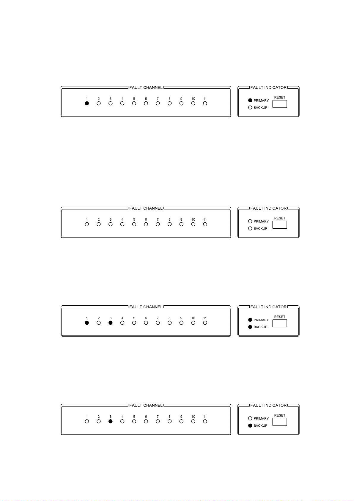
When a level error is detected on CH1 PRIMARY, the PRIMARY LED of FAULT
INDICATOR blinks and the FAULT CHANNEL 1 LED illuminates.
Figure 4-12 Error detection example 1
To release the error, apply a normal signal to CH1 PRIMARY and press the RESET key
of the FAULT INDICATOR section.
(However, key operation is enabled only when KEY LOCK is OFF.)
The error is released when the PRIMARY and FAULT CHANNEL 1 LEDs turn OFF.
(The error release procedure for BACKUP error as well as both PRIMARY and BACKUP
errors is also the same.)
Figure 4-13 Releasing the error of example 1
<Example 2> When errors occur on multiple channels
When an error is detected on CH1 PRIMARY and CH3 BACKUP, the PRIMARY and
BACKUP LEDs blink and the FAULT CHANNEL 1 and FAULT CHANNEL 3 LEDs
illuminate.
Figure 4-14 Error detection example 2
If a normal signal is applied to CH1 PRIMARY but CH3 BACKUP remains in error and
you press the RESET key of the FAULT INDICATOR section, the PRIMARY and FAULT
CHANNEL 1 LEDs turn OFF, but the BACKUP LED remains blinking, and the FAULT
CHANNEL 3 LED remains illuminated.
Figure 4-15 Releasing the error of example 2
22
Page 30

4. OPERATING PROCEDURE
4.12 Auto Switching Function
When set to SWITCH FAULT, a switch is made to the other
signal (PRIMARY/BACKUP) when a level error is detected in
the signal being passed to OUTPUT.
Use this setting in the normal case.
If an error is detected and a switch is made from the
PRIMARY to BACKUP and then the error of PRIMARY is
corrected and an error occurs in the BACKUP signal, the
signal is not switched automatically back to PRIMARY
(while the PRIMARY LED of FAULT INDICATOR remains
blinking and you do not press the RESET key).
When set to DISABLED, auto switching is not performed even
when a level error is detected in the signal being passed
OUTPUT.
Use this setting if you only wish to detect errors and not
perform auto switching.
4.12.1 When set to NORMAL and AUTO SWITCHING SWITCH FAULT
Figure 4-16 Auto Switching
Figure 4-17 NORMAL and AUTO SWITCHING SWITCH FAULT
The output signal is automatically switched to the normal input signal.
The output signal maintains the current setting when both signals are normal or
erroneous. You can change this so that output signal is toggled by switching the SYNC
SOURCE switch.
Use this setting in the normal case.
23
Page 31

4. OPERATING PROCEDURE
4.12.2 When set to NORMAL and AUTO SWITCHING DISABLED
Figure 4-18 NORMAL and AUTO SWITCHING DISABLED
The output signal maintains the current setting regardless of the status of the input
signal.
If you switch the SYNC SOURCE switch, the output signal can be toggled when both
the input signals are normal or erroneous. If only one of input signals is normal, the
output switches to the normal input signal. Switch to the error signal is not possible.
Normally, use the setting described in section 4.12.1, “When set to NORMAL and
AUTO SWITCHING SWITCH FAULT.”
4.12.3 When set to OVERRIDE and AUTO SWITCHING SWITCH FAULT
Figure 4-19 OVERRIDE and AUTO SWITCHING SWITCH FAULT
The operation of this combination is the same as the operation described in section
4.12.1, “When set to NORMAL and AUTO SWITCHING SWITCH FAULT.”
See 4.12.1.
4.12.4 When set to OVERRIDE and AUTO SWITCHING DISABLED
Figure 4-20 OVERRIDE and AUTO SWITCHING DISABLED
The output signal maintains the current setting regardless of the status of the input
signal.
If you switch the SYNC SOURCE switch, the output signal can be toggled regardless
of the status of the input signal.
Normally, use the setting described in section 4.12.1, “When set to NORMAL and
AUTO SWITCHING SWITCH FAULT.”
24
Page 32
4. OPERATING PROCEDURE
4.13 LIST OF OPERATING STATUS
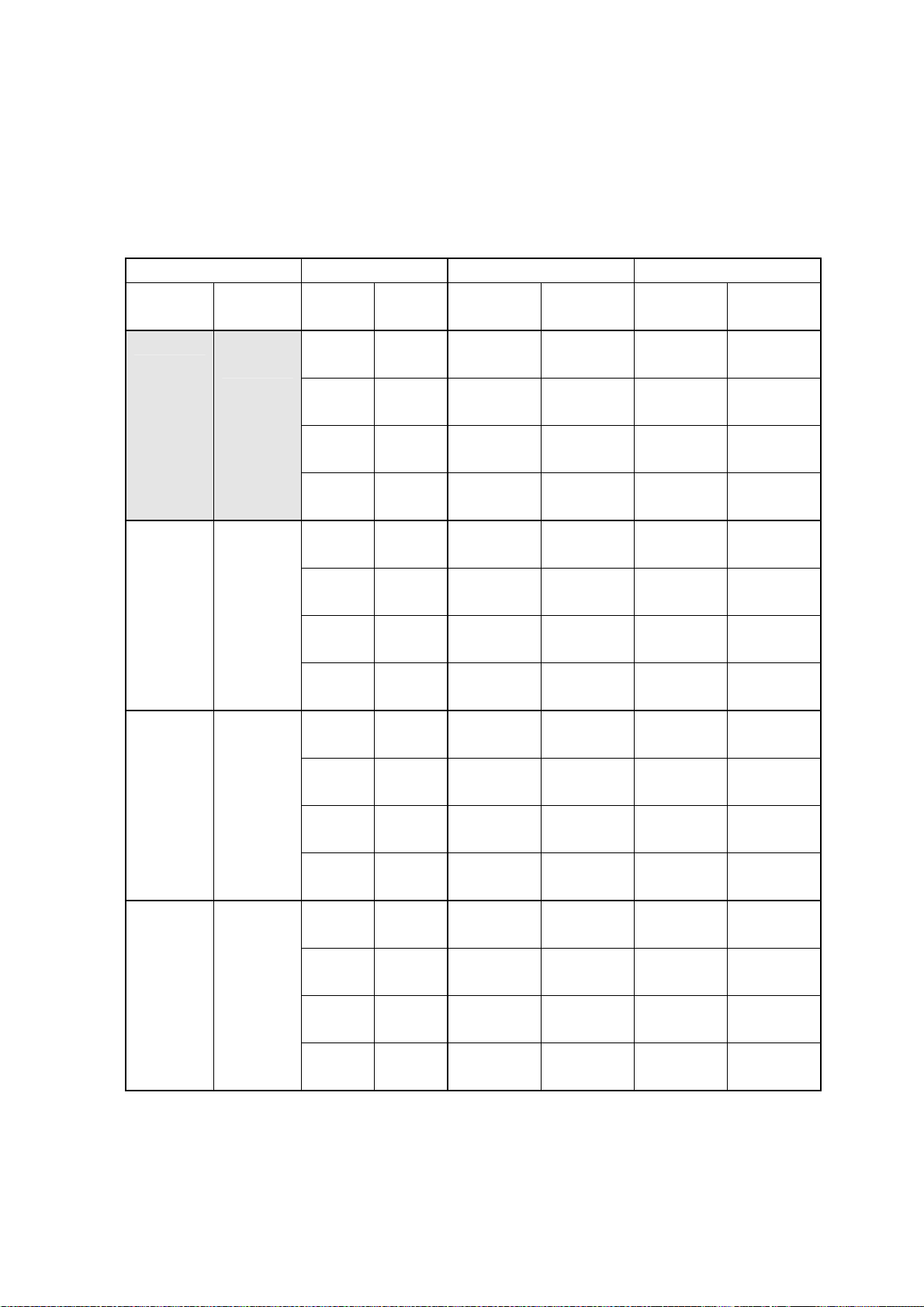
Normally, use the shaded settings.
Settings of other sections are available for manual operation and maintenance. They are
not usually used.
Table 4-3 List of operating status
Settings Input Signal Status SYNC SOURCE : PRIMARY SYNC SOURCE : BACKUP
MODE AUTO
SWITCHING
NORMAL SWITCH
FAULT
NORMAL DISABLED
OVERRIDE SWITCH
FAULT
OVERRIDE DISABLED
PRIMARY BACKUP OUTPUT SYNC
Fault Fault Remains at
Fault Normal Switch to
Normal Fault Remains at
Normal Normal Remains at
Fault Fault Remains at
Fault Normal Remains at
Normal Fault Remains at
Normal Normal Remains at
Fault Fault Remains at
Fault Normal Switch to
Normal Fault Remains at
Normal Normal Remains at
Fault Fault Remains at
Fault Normal Remains at
Normal Fault Remains at
Normal Normal Remains at
PRIMARY
BACKUP
PRIMARY
PRIMARY
PRIMARY
PRIMARY
PRIMARY
PRIMARY
PRIMARY
BACKUP
PRIMARY
PRIMARY
PRIMARY
PRIMARY
PRIMARY
PRIMARY
SOURCE SW
Switch to
BACKUP
Switch to
BACKUP
Remains at
PRIMARY
Switch to
BACKUP
Switch to
BACKUP
Switch to
BACKUP
Remains at
PRIMARY
Switch to
BACKUP
Switch to
BACKUP
Switch to
BACKUP
Remains at
PRIMARY
Switch to
BACKUP
Switch to
BACKUP
Switch to
BACKUP
Switch to
BACKUP
Switch to
BACKUP
OUTPUT SYNC
SOURCE SW
Remains at
BACKUP
Remains at
BACKUP
Switch to
PRIMARY
Remains at
BACKUP
Remains at
BACKUP
Remains at
BACKUP
Remains at
BACKUP
Remains at
BACKUP
Remains at
BACKUP
Remains at
BACKUP
Switch to
PRIMARY
Remains at
BACKUP
Remains at
BACKUP
Remains at
BACKUP
Remains at
BACKUP
Remains at
BACKUP
Switch to
PRIMARY
Remains at
BACKUP
Switch to
PRIMARY
Switch to
PRIMARY
Switch to
PRIMARY
Remains at
BACKUP
Switch to
PRIMARY
Switch to
PRIMARY
Switch to
PRIMARY
Remains at
BACKUP
Switch to
PRIMARY
Switch to
PRIMARY
Switch to
PRIMARY
Switch to
PRIMARY
Switch to
PRIMARY
Switch to
PRIMARY
25
Page 33

5. REMOTE CONTROL
5. REMOTE CONTROL
Connector used : Dsub 9 pin female (Inch screws for fixing the shell)
Figure 5-1 REMOTE connector
Table 5-1 Remote connector functions
Pin
No.
1 AUTO SWITCHING I When the front-panel AUTO SWITCHING is set to SWITCH FAULT,
2 SYNC SOURCE I Each time a low signal is applied, SYNC SOURCE switches between
3 SYNC SOURCE
(PRIMARY)
4 SYNC SOURCE
(BACKUP)
5 FAULT INDICATOR O Transmits a high signal when an error occurs in PRIMARY or BACKUP.
6 RESET I Apply a low signal to reset errors.
7 FAULT INDICATOR+
8 FAULT INDICATOR-
9 GND - Ground
Name I/O Description
applying a low signal sets AUTO SWITCHING to DISABLED, and
applying a high signal (or opening the circuit) sets AUTO SWITCHING to
SWITCH FAULT.
When the front-panel AUTO SWITCHING is set to DISABLED, remote
control is not possible. Set AUTO SWITCHING to SWITCH FAULT using
keys to enable remote control.
PRIMARY and BACKUP.
O Transmits a high signal when SYNC SOURCE is set to PRIMARY.
O Transmits a high signal when SYNC SOURCE is set to BACKUP.
Even when the error clears, the LT 4440/LT 444 retains the high signal
until the error is reset.
O Open during normal operation. Conducts current when the power is not
on or when there is an error in the input signal.
Use these pair of pins when you want to electrically isolate the
connected device from the LT 4440/LT 444.
(There is a photocoupler inside the LT 4440/LT 444 that is used for
isolation.)
26
Page 34

5. REMOTE CONTROL
Table 5-2 Remote connector I/O specifications
Pin
I/O I/O Specifications Connection example
No.
I
1
2
Connect a switch to apply a low signal.
Connect one side of the switch to the
remote connector and the other side to
ground.
6
O
3
4
5 O
7 8 O -
Connect an LED so that it will light
when a high signal is transmitted.
Connect the anode to the remote
connector and the cathode to ground.
27
Page 35

6. APPLICATIONS
A setup example is given for the case when CH1 is set to NTSC BB, CH2 is set to HD-SDI,
CH3 is set to DIGITAL AUDIO, and all other channels are set to no input signal.
6.1 Connection
In this example, the signals are connected as shown in Figure 6-1.
(However, do not connect the signals until the setup is complete in order to prevent
erroneous operation on the receiving device.)
Backup DIGITAL AUDIO signal
Primary DIGITAL AUDIO signal
Backup HD-SDI signal
Primary HD-SDI signal
6. APPLICATIONS
Backup NTSC BB signal
Primary NTSC BB signal
To the DIGITAL AUDIO
signal input of the system
To the HD-SDI signal
input of the system
To the NTSC BB signal
input of the system
Figure 6-1 Connection example
28
Page 36

6.2 Dipswitch Setup Procedure
1. Remove the four screws from the dipswitch cover on the top of the instrument.
2. Refer to Table 3-4, “Signal selection switch (CH1 to CH11)” and set the dipswitch so
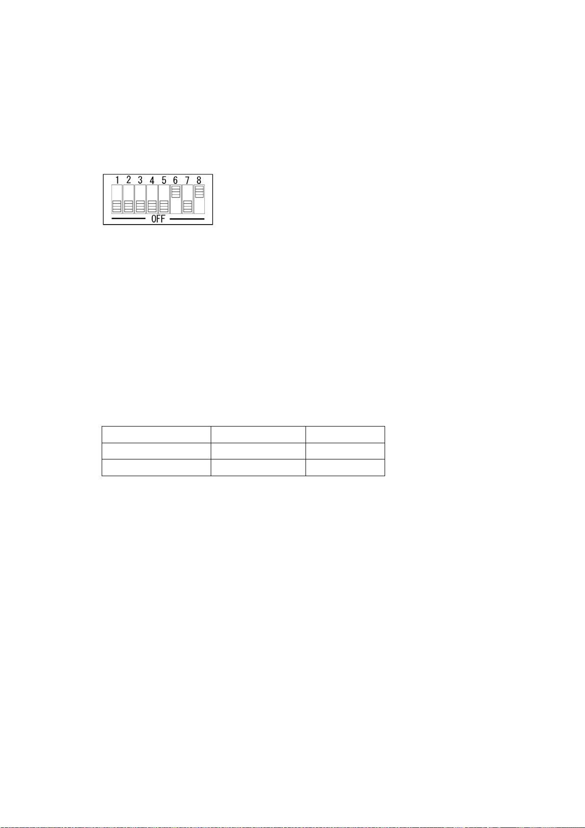
that CH1 is set to NTSC BB, CH2 is set to HD-SDI, CH3 is set to DIGITAL AUDIO,
and all other channels are set to no input signal. Set all the dipswitches for CH4 to
CH11 to OFF.
3. Set the error detection sensitivity. Normally, select VREF LOW.
4. Set the MODE switch. Normally set SW1 to Normal Operation and SW2 to FAST
Mode.
5. For the dipswitch settings, see Figure 6-2, “Dipswitch Setup Example.”
6. Set KEY LOCK to OFF and check that a normal signal is output from OUTPUT
regardless of whether SYNC SOURCE is set to PRIMARY or BACKUP.
7. Connect the OUTPUT signal to the system and attach the dipswitch cover on the top
of the instrument.
6. APPLICATIONS
Figure 6-2 Dipswitch Setup Example
29
Page 37

6.3 Panel Setup
The panel setup for the example is described below.
1. Press the KEY LOCK key to illuminate the OFF LED.
2. Press the SYNC SOURCE key to illuminate the PRIMARY LED.
3. Press the AUTO SWITCHING key to illuminate the SWITCH FAULT LED.
4. Check that the PRIMARY and BACKUP LEDs of FAULT INDICATOR are not
illuminated.
5. Press the KEY LOCK key to illuminate the ON LED.
6. APPLICATIONS
Figure 6-3 Panel Setup Example
30
Page 38

7. FACTORY DEFAULT SETTINGS
7. FACTORY DEFAULT SETTINGS
Below are the factory default settings of the dipswitch on the LT 4440/LT 444.
Error detection on all channels is disabled. Set the dipswitch according to the type of signal
used before starting operation.
Table 7-1 Factory default dipswitch settings
Dipswitch Setup Item Description Dipswitch Setting
MODE NORMAL MODE SW1: ON
Startup time Approx. 1 minute MODE SW2: ON
Error detection level selection switch Low level VREF LOW SW1 to SW8 : All ON
Signal selection switch Signal not selected SW1 to SW8 of CH1 to CH11 : All OFF
VREF HIGH SW1 to SW8 : All OFF
31
Page 39

8. PREVENTING POWER CORD DESCRIPTION
8. PREVENTING POWER CORD DESCRIPTION
To prevent power cord disconnection from the AC inlet, the Cover/Inlet stopper is supplied
with the instrument. Refer to the procedure below.
8.1 Connecting the Power Cord
1 Insert the power cord connector into the AC inlet.
2 Place the Cover/Inlet stopper on top of the connector as shown below.
3 Press the cover until it clicks into place.
4 Confirm that the Cover/Inlet stopper is locked to the base.
32
Page 40

8. PREVENTING POWER CORD DESCRIPTION
8.2 Disconnecting the Power Cord
1 Press the levers on the Cover/Inlet stopper with your fingers to release the lock.
2 Remove the Cover/Inlet stopper from the base.
3 Disconnect the power cord connector from the AC inlet.
33
Page 41

9. MAINTENANCE
The LT 4440/LT 444 is designed to operate stably under normal handling. If you have
questions regarding output calibration and service, contact your local Leader agent.
9. MAINTENANCE
34
Page 42

Following information is for Chinese RoHS only
所含有毒有害物质信息
部件号码:
此标志适用于在中国销售的电子信息产品,依据2006年2月28日公布的
《电子信息产品污染控制管理办法》以及SJ/T11364-2006《电子信息产品污染
控制标识要求》,表示该产品在使用完结后可再利用。数字表示的是环境保护使
用期限,只要遵守与本产品有关的安全和使用上的注意事项,从制造日算起在数
字所表示的年限内,产品不会产生环境污染和对人体、财产的影响。
产品适当使用后报废的方法请遵从电子信息产品的回收、再利用相关法令。
详细请咨询各级政府主管部门。
部件名称
Parts 铅 汞 镉 六价铬 多溴联苯 多溴二苯醚
实装基板 × ○ ○ ○ ○ ○
主体部 × ○ ○ ○ ○ ○
上蓋 ○ ○ ○ ○ ○ ○
底座 ○ ○ ○ ○ ○ ○
前框 ○ ○ ○ ○ ○ ○
電源部 × ○ ○ ○ ○ ○
线材料一套 ○ ○ ○ ○ ○ ○
附件 ○ ○ ○ ○ ○ ○
包装材 ○ ○ ○ ○ ○ ○
有毒有害物质或元素 Hazardous Substances in each Part
(Pb) (Hg) (Cd) (Cr(Ⅵ)) (PBB) (PBDE)
LT 444/4440
产品中有毒有害物质或元素的名称及含量
备注)
○:表示该有毒有害物质在该部件所有均质材料中的含量均在SJ/T11363-2006 规定的限量要求以下。
×:表示该有毒有害物质或元素至少在该部件的某一均质材料中的含量超出SJ/T11363-2006
标准规定的限量要求。
Ver.2
Page 43

LEADER ELECTRONICS CORP.
2-6-33 Tsunashima-Higashi, Kohoku-ku, Yokohama 223-8505, Japan
PHONE:81-45-541-2123 FAX:81-45-541-2823 http://www.leader.co.jp
July 17, 2012 Ver.4
 Loading...