

LEADER TEST INSTRUMENTS
MODEL LAG-27 AUDIO GENERATOR SINE - SQUARE
INSTRUCTION MANUAL
LEADER ELECTRONICS CORP.
Model LAG-27 AUDIO GENERATOR TABLE OF CONTENTS
| SECTIC | N | PAGE | E |
|---|---|---|---|
| 1 | DES | CRIPTION | 1 |
| 1.1 | General | 1 | |
| 1.2 | Specifications | 1 | |
| 1.3 | Controls and Terminals | 2 | |
| 2 | OPE | RATION | 3 |
| 2.1 | Precautions in Use | 3 | |
| 2.2 | Interconnections | 4 | |
| 2.3 | Sine Wave Output | 5 | |
| 2.4 | Square Wave Output | 7 | |
| 2.5 | Use of the Synchronizing Feature | 8 | |
| 2.6 | Supplementary Notes on Operation | 9 | |
| 2.7 | The Line Voltage Changing 11 | 1 | |
| 3 | CIRC | CUIT DESIGN 12 | 2 |
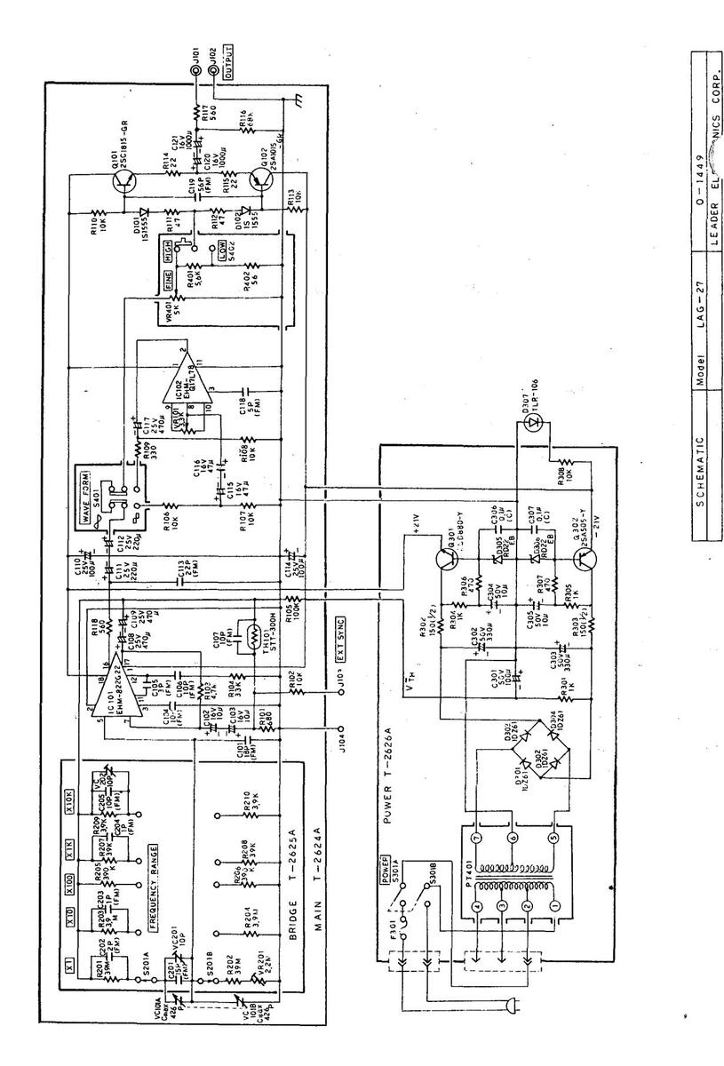
Schematic
SECTION 1 DESCRIPTION
1.1 General
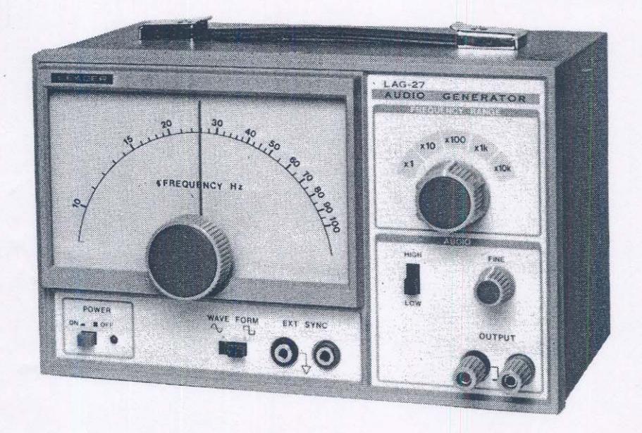
The LAG-27 is a handy generator of signals in the audio, supersonic and radio frequency ranges. It generates two types of waveforms, sine for general testing and square for transient response testing.
Using thick film integrated circuit (IC), synchronizing with an external frequency source, 600 Output impedance and compact construction are featured in this instrument.
1.2 Specifications
| - | |||||
|---|---|---|---|---|---|
| Frequency Range : | 10Hz to 1MHz in five decade bands. | ||||
| Accuracy : | ±(5%+2Hz) [10Hz to 1MHz] | ||||
| ±(3%+2Hz) [100Hz to 100kHz] | |||||
| Output Impedance : | 600Ω, unbalanced. | ||||
| Output Control : | HIGH, LOW (1/10), and fine adjuster. | ||||
| Sine Wave Output : | Range: 10Hz – 1MHz. | ||||
| Output voltage: 5Vrms or more (unloaded) | |||||
| Output Distortion: | |||||
| Less than 0.5%, 200Hz – 100kHz. | |||||
| Less than 1 %, 100Hz – 500kHz. | |||||
| Less than 2 %, 10Hz – 1MHz | |||||
| Output flatness: Less than ±1.5dB, ref. | |||||
| 1kHz. | |||||
| Square Wave Output : | Range: 10Hz – 100kHz | ||||
| Output voltage: 5Vp-p or more (unloaded) | |||||
| Rise time: Less than 200 ns | |||||
- 1 -
| Synchronization | : | Range: ±1% of oscillator frequency per |
|---|---|---|
| Vrms. | ||
| Input impedance: 10kΩ, approx. | ||
| Maximum input: 10Vrms. | ||
| Power Supply | : | 100, 115–120, 220–240V, 50/60Hz; |
| 3VA, approx. | ||
| Size and Weight | : | 150(H) x 238(W) x 130(D) mm; 2.5kg. |
1.3 Controls and Terminals
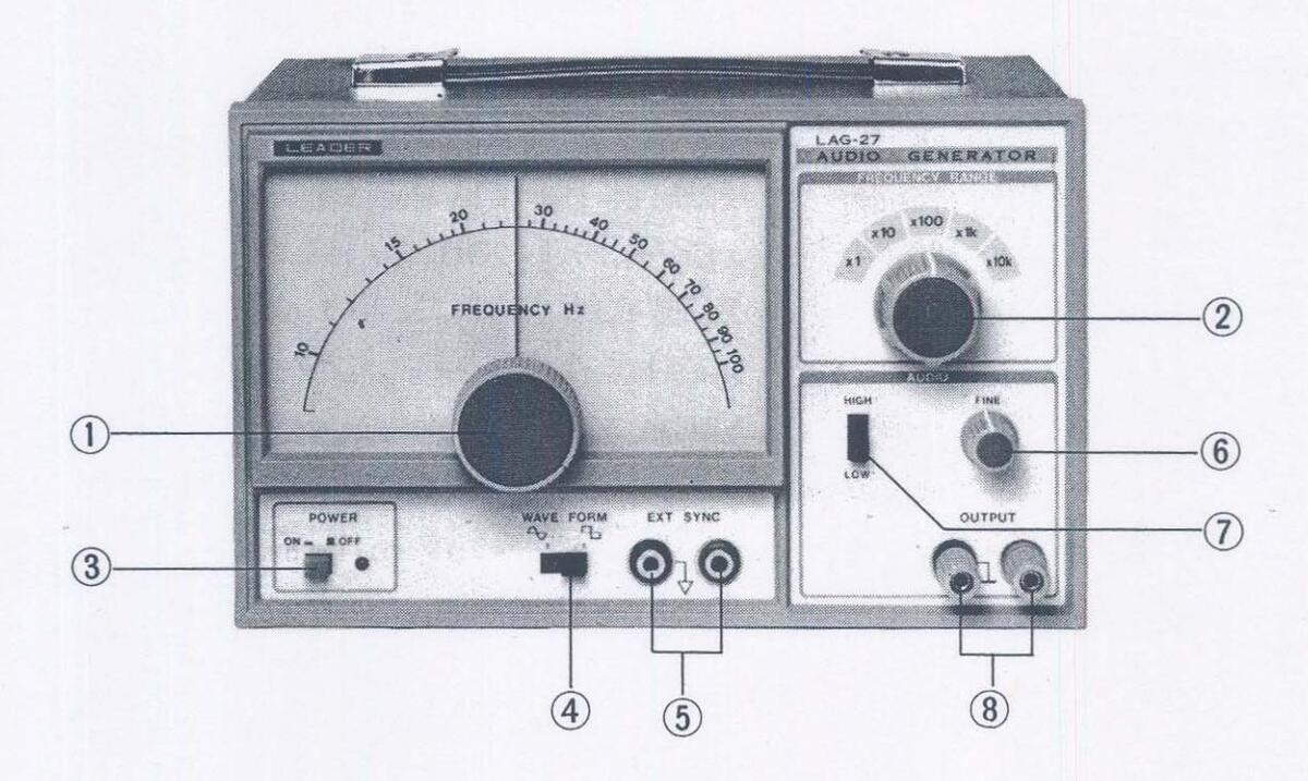
FREQUENCY Hz dial For setting the output signal frequency. FREQ. RANGE switch For selecting the frequency band: X1 10 - 100Hz X10 100 - 1000Hz
- 2 -
| ×100 1 – 10kHz | ||||||
|---|---|---|---|---|---|---|
| ×1k 10 – 100kHz | ||||||
| ×10k 100 – 1000kHz | ||||||
| 3 | POWER switch | For turning on the AC power. | ||||
| WAVEFORM switch | Selects the output signal waveform, | |||||
| sine or square. | ||||||
| (5) | EXT SYNC. input | For connection to external frequen- | ||||
| cy synchronizing signal. | ||||||
| 6 | FINE control | For continuous adjustment of out- | ||||
| put voltage. | ||||||
| 7 | HIGH-LOW switch | Sets the output level; at LOW, | ||||
| output is lowered by 1/100 (40dB). | ||||||
| 8 | OUTPUT terminals | For lead connections of output | ||||
| signal to load; source impedance | ||||||
| is approximately 600Ω. | ||||||
SECTION 2
OPERATION
2.1 Precautions in Use
1. The generator output should not be connected across circuits in which high DC or AC voltage is present. This is to prevent possible damage to the internal circuitry. When a DC voltage is present, connect a high grade capacitor, 20µF or more with ample voltage rating, in series with the "hot" lead.
The output connecting leads should be as short as possible to prevent pickup of unwanted noise. A long shielded cable will degrade the output response at
high frequencies, especially when square waves are in use.
3. Make certain the AC line voltage in use. The AC line voltage should be kept constant. This instrument should be operated in the ambient temperature between 5°C and 35°C. If the temperature is below 5°C, the harmonic distortion may increase. It should also be operated in low humidity circumstance, otherwise the frequency error may increase at x1 RANGE.
2.2 Interconnections
The basic interconnections in using the LAG-27 are shown in Fig. 2-1.
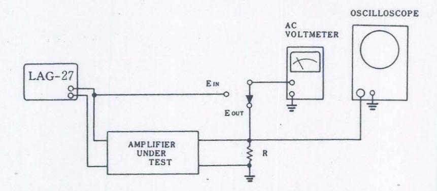
Fig. 2-1 Interconnections of the equipment.
The specified load resistance, R, is connected across the output of the test circuit. It should have a wattage rating of at least twice the expected maximum power output and be noninductive.
For measuring the input/output voltages, an electronic FET Voltmeter or VTVM, type is required. Leader LMV-181A i recommended.
An oscilloscope is required during measurements with the square wave output signal. Leader LBO-524 or LBO-514A is recommended.
- 4 -
2.3 Sine Wave Output
In most amplifier measurements, sine waves are used. In this section, directions will be given for typical applications.
A. Input/Output characteristic.
Control settings:
POWER switch at ON.
WAVEFORM switch at sine wave.
FREQ. RANGE switch at ×10 and dial at 100 for 1kHz.
OUTPUT switch initially at HIGH and FINE at fully counterclockwise.
Connect leads from the OUTPUT terminals to the input of the amplifier under test.
Advance the FINE control gradually. The output voltage will increase in proportion to the control setting.
When the amplifier is overloaded, there will be no apparent increase in the output voltage and the waveform distortion will be observed, usually flattening of one or both peaks of the trace.
The input and output voltages can be plotted on loglog graph paper. In this manner, the input voltage range of the amplifier can be determined easily.
VOLTAGE GAIN in dB = 20 log
When the ratio Eout/Ein is determined, reference should be made to a decibel table for the dB figure.
The results for voltage gain in dB can be plotted on semilog graph paper using the X-axis for Ein and the Y-axis for dB.
The power output is calculated from the following:
POWER OUTPUT, Po in WATTS = Eout2 R ohms
B. Frequency Response
The frequency response of an amplifier is determined by applying a constant voltage. This voltage is chosen so that the amplifier is operated below the overload point.
Set the reference frequency at 1kHz, or 400Hz, and set the output controls for a suitable output from the amplifier.
Note the input and output voltages.
Set the measuring frequencies with the FREQ RANGE switch and dial from 20Hz or higher if required.
Since the generator output is practically constant at all frequencies, the input voltage will not require any adjustment. However for the highest accuracy, the input at each frequency can be adjusted to the predetermined value.
The output readings can be simplified by noting the output level in dB at the reference frequency (1kHz or 400Hz). Then at each frequency the dB indication is noted and used in plotting the response curve. (NOTE: Disregard the 0dBm = 0.775V, etc. in this case. The dB readings can be read off directly since the voltmeter is connected across a constant impedance.)
The dB readings are added or subtracted from the 1kHz reference level.
Example: Let "dB" at 1kHz = -2dB. Assume that the measured values are as in (A) in the following data.
- 6 -
| FREQ (Hz) | 20 | 60 | 200 | 600 | 1K | 2K | 6K | 20K |
|---|---|---|---|---|---|---|---|---|
|
(A) dB
measured |
-6 | -5 | -2 | -2 | -2 | -2 | -1 | -6 |
| (B) dB | -4 | -3 | 0 | 0 | 0 | 0 | +1 | -4 |
The dB figures for (B) are used in plotting on a semilog graph paper with the X-axis for frequency and Y-axis for the relative response in dB.
In actual measurements, more frequency intervals than shown should be used.
2.4 Square Wave Output
Use of the square wave output is convenient in making rapid checks on amplifier performance. Various characteristics can be determined by observation of the output waveforms from the test amplifier on the scope.
The interconnections are identical with those for the sine wave operation with the following exceptions:
a. WAVEFORM switch is set at square wave.
b. Use of good scope is necessary, i.e. with fast rise time. The following chart shows the conditions for the amplifier output waveforms.
- 7 -
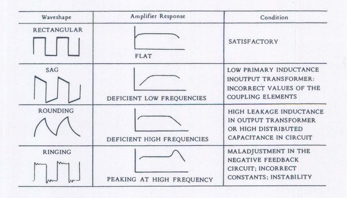
For an amplifier with good characteristics, the response will be flat up to about the 11th harmonic as indicated by a good square wave display. For example, if a square wave of 1kHz is reproduced without distortion, the amplifier response is flat to about 11kHz.
-
2.5 Use of the Synchronizing Feature
- A. General:
It is to be noted that there are two voltages present at the SYNC. terminals, namely, about 2V DC and AC of about 0.8Vrms at the oscillator frequency. The "input" or "output" resistance is approximately 10kΩ. These conditions must be taken into account when connections are made to the terminals.
A few applications of the synchronous control will be given.
B. Control from an external source:
The frequency of the oscillator can be synchronized with an accurate source. It is possible to control the frequency over a range of ±1% with an input of 1Vrms.
For example, when the oscillator is set at some point between 990 and 1010Hz, then by applying a signal at exactly 1kHz, 1Vrms, the oscillator will be locked in automatically to 1kHz. Thus, high accuracy in the output frequency is achieved with use of a precision frequency standard. Excessive input voltages, however will distort the output waveform.
In another application, a highly distorted waveform can be purified or "filtered" by passing it through the oscillator.
It is possible to lock the oscillator frequency with the harmonies of distorted waveforms provided the amplitudes, are of sufficient magnitude; at low amplitudes, the control range is narrowed.
C. Control of external equipment:
The synchronous output voltage should be sufficient to operate a frequency counter, or to synchronize or trigger the sweep in a scope. The voltage available is not affected by the setting of the output controls.
2.6 Supplementary Notes on Operation
A. Load Impedance:
The load impedance of the generator should be 600Ω. When the load is higher or lower, use of a matching pad or transformer is advised.
For high impedances, say over 10kΩ, connect a 600Ω resistor in parallel with the load.
- 9 -
For low-power low-impedance circuits, connect a resistor in series with the load. The total impedance should be 600Ω.
B. Stereo input pad:
When testing stereo circuits, equal voltage to the two input circuits can be applied with use of a matching pad as shown in Fig. 2-2.
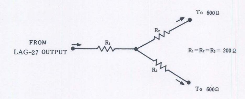
Fig. 2-2 Stereo input pad.
The voltage across the 600Ω loads at the outputs will be one-half that of the input voltage, or lower by 6dB.
C. Exposing the chassis:
The chassis can be exposed in the following manner for inspection:
- 1. Loosen one screw at front part of top cover.
- 2. Remove one screw on the bottom side.
3. Remove one screw at the back.
4. Take off the cover.
2.7 The Line Voltage Changing
This instrument can be operated from AC line sources of 100V, 115V-120V or 220V-240V.
The Line Voltage Selector (pin connector with plastic cover) allows one of three voltages to be selected.
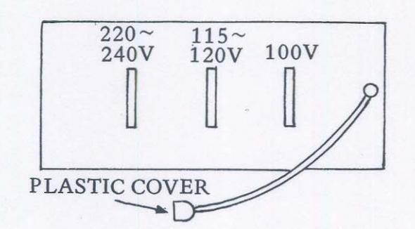
To select the desired line voltage, proceed as follows:
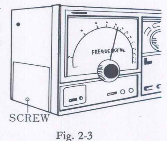
- 1. DISCONNECT THE INSTRU-MENT FROM THE POWER SOURCE.
- 2. Remove screw on the right side of the instrument then take the cover off. (Ref: Fig. 2-3)
- 3. Move the Line Voltage Selector to the desired voltage position. (Ref: Fig. 2-4)
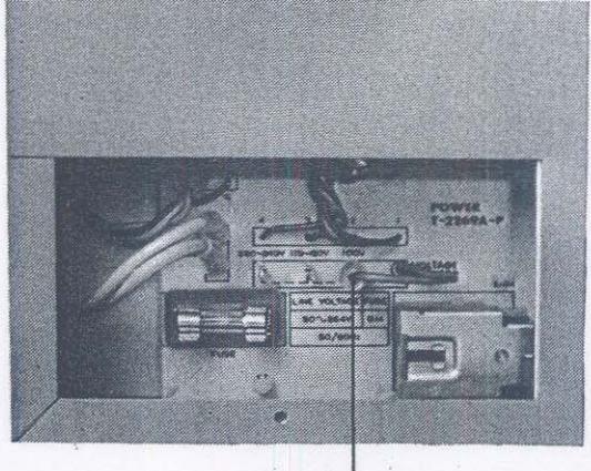
LINE VOLTAGE SELECTOR
Fig. 2-4
SECTION 3 CIRCUIT DISIGN
The block diagram of the LAG-27 is shown in Fig. 3-1. In the circuit description which follows, reference will be made to the components as designated on the schematic.
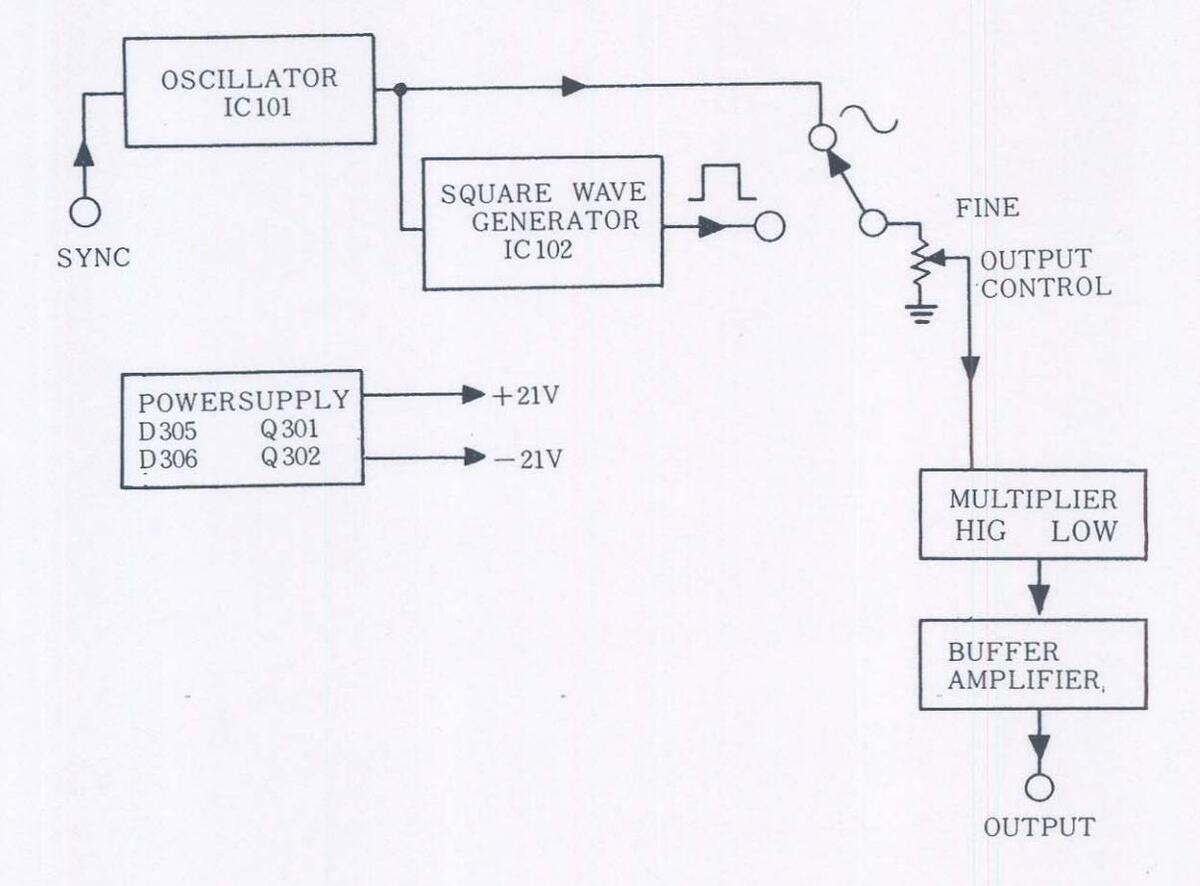
Fig. 3-1 Block diagram: LAG-27
The well-known Wien-bridge configuration is used in the oscillator. The frequency determining elements are the switched resistors R201-R210, for ranging and a two-gang variable capacitor, VC101A-B, for tuning. An IC, IC101 make up the oscillator-amplifier. Negative feedback is applied to IC101 through the thermistor ST101. The thermistor serves to stabilize the output to maintain a constant
voltage and further to produce pure sine waves. When the output voltage is low, the current in TH101 decreases and its resistance is increased to lower the negative feedback voltage, and vice versa. 'his action keeps the output at a constant value.
Small trimmers, VC201 and VC202, are used for fine frequency these are preset at the factory.
The square wave is produced by feeding the sine wave from the oscillator to the Schmitt trigger type waveshaper, IC102. The preserve the symettrical waveform, an adjuster, VR101, is used to apply the proper bias to the IC102.
For synchronizing the oscillator frequency with an external source, the signal is connected to the IC101 in the oscillator circuit. The output frequency control range is ±1% per volt rms applied.
The output level is controlled by S402 and VR104.
The signal will come out from J101 through the buffer amplifier which consists of Q101 and Q102.
The DC voltage at approximately +21V and -21V for operation is supplied from a rectifier-filter system and two transistors-zener diodes, Q301-D305 and Q302-D306 regulators.
The power transformer, T401, has its primary windings with three taps; 100V, 115–120V, 220–240V. It is easy to change line voltage. The LED, D307 is permanently connected across the -21V power supply through the R308.
- 14 --
LEADER ELECTRONICS CORP.
LEADER TEST INSTRUMENTS
2-6-33 TSUNASHIMA-HIGASHI, KOHOKU-KU, YOKOHAMA, JAPAN. . PHONE: (045) 541-2121 TELEX:J47780 JPLEADER
LEADER INSTRUMENTS CORP.
380 OSER AVENUE, HAUPPAUGE, N.Y. 11788 U.S.A. PHONE: (516) 231-6900 TELEX: 510-227-9669 LEADER HAUP
Printed in Japan.


 Loading...